EP1137131A1 - Optical amplifying component - Google Patents
Optical amplifying component Download PDFInfo
- Publication number
- EP1137131A1 EP1137131A1 EP01105360A EP01105360A EP1137131A1 EP 1137131 A1 EP1137131 A1 EP 1137131A1 EP 01105360 A EP01105360 A EP 01105360A EP 01105360 A EP01105360 A EP 01105360A EP 1137131 A1 EP1137131 A1 EP 1137131A1
- Authority
- EP
- European Patent Office
- Prior art keywords
- amplifying medium
- optical amplifying
- temperature
- edf
- optical
- Prior art date
- Legal status (The legal status is an assumption and is not a legal conclusion. Google has not performed a legal analysis and makes no representation as to the accuracy of the status listed.)
- Withdrawn
Links
- 230000003287 optical effect Effects 0.000 title claims abstract description 97
- 239000013307 optical fiber Substances 0.000 claims abstract description 37
- 239000000758 substrate Substances 0.000 claims abstract description 30
- 239000012533 medium component Substances 0.000 claims description 44
- 238000005086 pumping Methods 0.000 claims description 12
- 229910052761 rare earth metal Inorganic materials 0.000 claims description 10
- 238000005452 bending Methods 0.000 claims description 3
- 230000005679 Peltier effect Effects 0.000 abstract description 22
- 238000001816 cooling Methods 0.000 abstract description 9
- 238000010438 heat treatment Methods 0.000 abstract description 9
- 239000000306 component Substances 0.000 description 8
- 239000004809 Teflon Substances 0.000 description 5
- 229920006362 Teflon® Polymers 0.000 description 5
- 239000000835 fiber Substances 0.000 description 5
- 230000005540 biological transmission Effects 0.000 description 4
- 239000000463 material Substances 0.000 description 4
- 230000009471 action Effects 0.000 description 3
- 230000003321 amplification Effects 0.000 description 2
- 230000007423 decrease Effects 0.000 description 2
- 238000010586 diagram Methods 0.000 description 2
- 238000010030 laminating Methods 0.000 description 2
- 238000000034 method Methods 0.000 description 2
- 238000003199 nucleic acid amplification method Methods 0.000 description 2
- 230000003247 decreasing effect Effects 0.000 description 1
- 230000000694 effects Effects 0.000 description 1
- 238000005516 engineering process Methods 0.000 description 1
- 230000007613 environmental effect Effects 0.000 description 1
- 230000005281 excited state Effects 0.000 description 1
- 230000006872 improvement Effects 0.000 description 1
- 230000004048 modification Effects 0.000 description 1
- 238000012986 modification Methods 0.000 description 1
- 238000012544 monitoring process Methods 0.000 description 1
- 150000002910 rare earth metals Chemical class 0.000 description 1
- 230000004044 response Effects 0.000 description 1
- 239000004065 semiconductor Substances 0.000 description 1
- 238000001228 spectrum Methods 0.000 description 1
- 230000000087 stabilizing effect Effects 0.000 description 1
Images



Classifications
-
- H—ELECTRICITY
- H01—ELECTRIC ELEMENTS
- H01S—DEVICES USING THE PROCESS OF LIGHT AMPLIFICATION BY STIMULATED EMISSION OF RADIATION [LASER] TO AMPLIFY OR GENERATE LIGHT; DEVICES USING STIMULATED EMISSION OF ELECTROMAGNETIC RADIATION IN WAVE RANGES OTHER THAN OPTICAL
- H01S3/00—Lasers, i.e. devices using stimulated emission of electromagnetic radiation in the infrared, visible or ultraviolet wave range
- H01S3/05—Construction or shape of optical resonators; Accommodation of active medium therein; Shape of active medium
- H01S3/06—Construction or shape of active medium
- H01S3/063—Waveguide lasers, i.e. whereby the dimensions of the waveguide are of the order of the light wavelength
- H01S3/067—Fibre lasers
- H01S3/06704—Housings; Packages
-
- H—ELECTRICITY
- H01—ELECTRIC ELEMENTS
- H01S—DEVICES USING THE PROCESS OF LIGHT AMPLIFICATION BY STIMULATED EMISSION OF RADIATION [LASER] TO AMPLIFY OR GENERATE LIGHT; DEVICES USING STIMULATED EMISSION OF ELECTROMAGNETIC RADIATION IN WAVE RANGES OTHER THAN OPTICAL
- H01S3/00—Lasers, i.e. devices using stimulated emission of electromagnetic radiation in the infrared, visible or ultraviolet wave range
- H01S3/10—Controlling the intensity, frequency, phase, polarisation or direction of the emitted radiation, e.g. switching, gating, modulating or demodulating
- H01S3/13—Stabilisation of laser output parameters, e.g. frequency or amplitude
- H01S3/1301—Stabilisation of laser output parameters, e.g. frequency or amplitude in optical amplifiers
- H01S3/13017—Stabilisation of laser output parameters, e.g. frequency or amplitude in optical amplifiers by controlling the temperature of the active medium
-
- H—ELECTRICITY
- H01—ELECTRIC ELEMENTS
- H01S—DEVICES USING THE PROCESS OF LIGHT AMPLIFICATION BY STIMULATED EMISSION OF RADIATION [LASER] TO AMPLIFY OR GENERATE LIGHT; DEVICES USING STIMULATED EMISSION OF ELECTROMAGNETIC RADIATION IN WAVE RANGES OTHER THAN OPTICAL
- H01S3/00—Lasers, i.e. devices using stimulated emission of electromagnetic radiation in the infrared, visible or ultraviolet wave range
- H01S3/02—Constructional details
- H01S3/04—Arrangements for thermal management
- H01S3/0405—Conductive cooling, e.g. by heat sinks or thermo-electric elements
-
- H—ELECTRICITY
- H01—ELECTRIC ELEMENTS
- H01S—DEVICES USING THE PROCESS OF LIGHT AMPLIFICATION BY STIMULATED EMISSION OF RADIATION [LASER] TO AMPLIFY OR GENERATE LIGHT; DEVICES USING STIMULATED EMISSION OF ELECTROMAGNETIC RADIATION IN WAVE RANGES OTHER THAN OPTICAL
- H01S3/00—Lasers, i.e. devices using stimulated emission of electromagnetic radiation in the infrared, visible or ultraviolet wave range
- H01S3/05—Construction or shape of optical resonators; Accommodation of active medium therein; Shape of active medium
- H01S3/06—Construction or shape of active medium
- H01S3/063—Waveguide lasers, i.e. whereby the dimensions of the waveguide are of the order of the light wavelength
- H01S3/067—Fibre lasers
- H01S3/06754—Fibre amplifiers
-
- H—ELECTRICITY
- H01—ELECTRIC ELEMENTS
- H01S—DEVICES USING THE PROCESS OF LIGHT AMPLIFICATION BY STIMULATED EMISSION OF RADIATION [LASER] TO AMPLIFY OR GENERATE LIGHT; DEVICES USING STIMULATED EMISSION OF ELECTROMAGNETIC RADIATION IN WAVE RANGES OTHER THAN OPTICAL
- H01S3/00—Lasers, i.e. devices using stimulated emission of electromagnetic radiation in the infrared, visible or ultraviolet wave range
- H01S3/10—Controlling the intensity, frequency, phase, polarisation or direction of the emitted radiation, e.g. switching, gating, modulating or demodulating
- H01S3/10007—Controlling the intensity, frequency, phase, polarisation or direction of the emitted radiation, e.g. switching, gating, modulating or demodulating in optical amplifiers
- H01S3/10013—Controlling the intensity, frequency, phase, polarisation or direction of the emitted radiation, e.g. switching, gating, modulating or demodulating in optical amplifiers by controlling the temperature of the active medium
Definitions
- the present invention relates to an optical amplifying medium component and an optical fiber amplifier comprising the optical amplifying medium component.
- an optical amplifying medium component comprising a rare-earth doped fiber as an optical amplifying medium and having the function of maintaining the temperature of such a fiber constant.
- WDM Wavelength Division Multiplexing
- the WDM system can easily increase the transmission capacity of the optical fiber by extending the range of bandwidths to increase the number of optical signals to be multiplexed.
- the optical fiber amplifier is required to be one having flat wavelength characteristics of gain (i.e., the increase in the amplitude of a signal is constant) with respect to the broad bandwidth.
- optical signals at a wavelength band of 1550 nm is generally used.
- an erbium-doped optical fiber (EDF) is used as an optical amplifying medium.
- an optical amplifying medium component comprises: an optical amplifying medium for amplifying signal light; a first substrate on which the optical amplifying medium is placed; a second substrate opposite to the fist substrate to sandwich the optical amplifying medium between the fist substrate and the second substrate; and a first temperature control element for controlling the temperature of the fist element.
- the optical amplifying medium component may further comprise: a second temperature control element for controlling the second substrate.
- the optical amplifying medium may be a rare-earth element doped optical fiber.
- the optical amplifying medium component may further comprise: a temperature-detecting device for detecting temperature at a predetermined place in the proximity of the optical amplifying medium.
- the rare-earth element doped optical fiber may be placed in a plane without bending and crossing; and the rare-earth element doped optical fiber and the temperature-detecting device are sandwiched between the first substrate and the second substrate.
- an optical fiber amplifier comprises: an optical amplifying medium component; a pumping light source for producing pumping light; and an optical multiplexer for multiplexing the pumping light with signal light to send them to the optical amplifying medium.
- the optical amplifying medium component includes an optical amplifying medium for amplifying signal light, a first substrate on which the optical amplifying medium is placed, a second substrate opposite to the fist substrate to sandwich the optical amplifying medium between the fist substrate and the second substrate, and a first temperature control element for controlling the temperature of the fist element.
- the optical amplifying medium component may further comprise: a second temperature control element for controlling the second substrate.
- the optical amplifying medium may be a rare-earth element doped optical fiber.
- the optical amplifying medium component may further comprise: a temperature control circuit for adjusting temperature at a predetermined place in the proximity of the optical amplifying medium. If the relationship between the temperature and the wavelength characteristics of gain are investigated in advance, a temperature control circuit may be used for actively adjusting the temperature of the optical amplification medium in the optical amplifying medium component. Therefore, it allows to keep the such a medium entirely at a predetermined temperature so as to obtain desired wavelength characteristics of gain thereof. In this case, the action of gain equalization can be achieved.
- wavelength multiplexing has been performed at a wavelength band of 1550 nm (designated as a C-band) in general.
- a wavelength band of 1580 nm designated as L-band
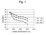
- Fig. 1 shows the wavelength characteristics of gain in an erbium-doped fiber (EDF) at the L-band.
- EDF erbium-doped fiber
- Fig. 2 is an example of the configuration of the conventional temperature-compensated EDF component well known in the art.
- the conventional temperature-compensated EDF component comprises a peltier-effect device 2, an EDF 3 provided as an optical amplifying medium, a thermister 4, and a reel 6. Both the peltier-effect device 2 and the thermister 4 are mounted on the reel 6 while the EDF 3 is wound thereon, so that the temperature of the EDF 3 can be monitored and controlled by the peltier-effect device 2 and the thermister 4 through the reel 6.
- the EDF 3 has a portion touched on the surface of the reel 6 and the rest not touched thereon.
- the wavelength-characteristics of gain in the EDF 3 is shown in Fig. 3. As shown in Fig. 3, the gain fluctuates in a range of about 1.5 dB as the surrounding temperature is changed in a range of 0 to 60 °C, so that the gain fluctuation is in need of further improvement.
- novel optical amplifying medium components and novel optical fiber amplifiers that comprise their respective optical amplifying medium components in accordance with the present invention.
- An optical amplifying medium component as a first preferred embodiment of the present invention is capable of adjusting the temperature of a rare-earth element doped optical fiber provided as an optical amplifying medium to ensure a uniform temperature distribution through the fiber such that wavelength characteristics of gain and output of the fiber remain invariant while the surrounding temperature varies.
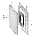
- Fig. 4 is a schematic perspective view of the optical amplifying medium component of the present embodiment.
- the optical amplifying medium component comprises: a pair of substrates (i.e., Peltier effect devices) 2a and 2b provided as thin plates capable of heating and cooling any component thereon; and an optical fiber 3 provided as an optical amplifying medium, in which a rare-earth element is doped.
- the optical fiber 3 is an erbium-doped optical fiber (hereinafter, abbreviated as "EDF") and wound into a spiral in a plane.
- the spiral-shaped optical fiber 3 is sandwiched between sheet films described later to form an EDF sheet 1.
- the EDF sheet 1 is sandwiched between the Peltier effect devices 2a, 2b.
- These Peltier effect devices 2a, 2b are responsible for altering the surface temperature of the EDF sheet 1 by the passage of a driving current through these devices 2a, 2b to keep the EDF sheet 1 at a constant temperature.
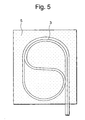
- Fig. 5 is a plane view that illustrates an EDF sheet 1 to be applied in the optical amplifying medium component shown in Fig. 4.
- the EDF sheet 1 is comprised of: an EDF 3 as an optical amplifying medium; and a temperature-sensitive semiconductor device (i.e.. thermister) 4 possessing a negative temperature coefficient so that resistance decreases as temperature increases.
- the EDF 3 and the thermister 4 are arranged in the same plane.
- the EDF 3 is an erbium-doped optical fiber of about 40 meter in length.
- both signal light and pumping light can be introduced into the EDF 3 from the same direction.
- the EDF 3 and the thermister 4 are arranged on one of sheet films 5 and then covered with another one to make a laminated sheet assembly 5 for keeping the EDF 3 from twisting, bending, and crossing.
- the sheet film 5 may be made of a Teflon-based films or the like.
- the thermister 4 is provided as a temperature sensor in which its resistance varies with the temperature variations. If the surrounding temperature is higher than ordinary temperature(about 25 °C), the resistance of the thermister 4 on the EDF sheet 1 is decreased. Then, the decrease in the resistance of the thermister 4 is monitored to permit the Peltier effect devices 2a, 2b to feed a driving current for cooling the EDF sheet 1. Therefore, the EDF sheet 1 can be kept at ordinary temperature (about 25 °C). On the other hand, if the surrounding temperature is lower than ordinary temperature, the resistance of the thermister 4 on the EDF sheet 1 is increased and monitored to permit the Peltier effect devices 2a, 2b to feed a driving current for heating the EDF sheet 1. Therefore, the EDF sheet 1 can be kept at ordinary temperature (about 25 °C). As described above, the optical amplifying medium component of the present embodiment allows to keep the temperature of the EDF sheet 1 at ordinary temperature (about 25 °C) regardless of the surrounding temperature.
- Fig. 6 shows wavelength characteristics of gain with respect to variations in the surrounding temperature when pumping light at a wavelength band of 1480 nm is introduced into the EDF sheet 1 from both directions with a power of 100 mW.
- the incident signal light is provided as 1580 nm wavelength-multiplexed signal light of -25 dBm per a wave. It is shown that the variations in wavelength characteristics of gain are within about 1 dB when the surrounding temperature varies in the range of 0 to 60 °C.
- the Peltier effect devices 2a, 2B are used for heating and cooling the EDF sheet 1.
- the heating and cooling devices are not limited to the Peltier effect devices 2a, 2b.
- Other thermal devices well known in the art may be applicable to heat and cool the EDF sheet 1.
- one of the Peltier effect devices 2a, 2b may be only provided on one side of the EDF sheet 1 instead of sandwiching the EDF sheet 1 with a pair of the Peltier effect devices 2a, 2b.
- the EDF sheet 1 may be subjected to a temperature control procedure using a thermal device capable of performing both heating and cooling operations, or using a heater or a cooler.
- the thermister is used as a temperature sensor. According to the present invention, however, any temperature sensor well known in the art may be used instead of the thermiser.
- the Teflon-based film is used as a material for laminating the EDF 3 after arranging it in position. According to the present invention, however, any material well known in the art may be used instead of the Teflon-based film.
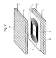
- Fig. 7 is a perspective view of an optical amplifying medium component as a second preferred embodiment of the present invention.
- the optical amplifying medium component is constructed by the same way as that of the first preferred embodiment shown in Figs. 4 to 6, except of the absence of thermister 4 in the present embodiment. That is, the optical amplifying medium component of the present embodiment comprises an EDF sheet 1 sandwiched between thin Peltier effect devices 2a and 2b.
- the Peltier effect devices 2a, 2b are responsible for altering the surface temperature of the EDF sheet 1 by the passage of a driving current through them to keep the EDF sheet 1 at a constant temperature.
- the thermister 4 is not installed on the device, so that the temperature of the EDF 3 can be controlled by monitoring variations in the spectrum of gain.
- the Peltier effect devices 2a, 2B are used for heating and cooling the EDF sheet 1.
- the heating and cooling devices are not limited to the Peltier effect devices 2a, 2b.
- Other thermal devices well known in the art may be also applicable to heat and cool the EDF sheet 1.
- the Peltier effect device may be only provided on one side of the EDF sheet 1 instead of sandwiching the EDF sheet 1 with a pair of the Peltier effect devices 2a, 2b.
- the EDF sheet 1 may be subjected to a temperature control procedure using a thermal device capable of performing both heating and cooling operations, or using a heater or a cooler.
- the thermister is used as a temperature sensor. According to the present invention, however, it is not limited to a specific type of the thermal sensor. Any temperature sensor well known in the art may be sued instead of the thermiser.
- the Teflon-based film is used as a material for laminating the EDF 3 after arranging it in position. According to the present invention, any material well known in the art may be used instead of the Teflon-based film.
- optical fiber amplifier on which the optical amplifying medium of the first or second preferred embodiment is applied.
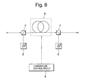
- Fig. 8 is a schematic diagram of an optical fiber amplifier as a third preferred embodiment of the present invention.
- the optical fiber amplifier comprises: an optical amplifying medium component 8 of the first or second preferred embodiment; pumping light sources 6 that produce pumping light to bring an optical amplifying medium in the component 8 to a excited state; and an optical multiplexer 7 that multiplexes pumping light with signal light to send them to the optical amplifying medium component 8.
- the optical amplifying medium may be excited in the forward or backward direction.
- the optical fiber amplifier has the function of keeping the optical amplifying medium at a constant temperature and stabilizing the wavelength characteristics of gain in the optical amplifying medium by applying the configuration of the optical amplifying medium component disclosed in the first or second preferred embodiment. If the relationship between the temperature and the wavelength characteristics of gain are investigated in advance, a temperature control circuit may be used for actively adjusting the temperature of the EDF 3 in the optical amplifying medium component 8. Therefore, it allows to keep the EDF 3 entirely at a predetermined temperature so as to obtain desired wavelength characteristics of gain. In this case, the action of gain equalization can be allowable.
- the optical fiber amplifier of the present embodiment comprises the optical amplifying medium component of the first or second preferred embodiment, so that an optical amplification can be performed while the wavelength characteristics of gain in the optical amplifying medium is stabilized.
- the EDF provided as the optical amplifying medium is configured in a sheet structure and the whole package provided as the EDF sheet is extremely compact, so that the EDF saves space in the optical fiber amplifier.
- the optical amplifying medium component of the present invention comprises an optical amplifying medium for optically amplifying signal light, a first substrate on which the optical amplifying medium is placed, a second substrate opposite to the fist substrate to sandwich the optical amplifying medium between the fist and second substrates, and a first temperature control element for controlling the temperature of the fist element.
- a second temperature control element for controlling the second substrate may be also installed on the optical fiber amplifier.
- an optical amplifying medium e.g., EDF
- EDF optical amplifying medium with a sheet shape
- thin Peltier effect devices to allow the passage of a driving current of the Peltier effect devices through the optical amplifying medium, so that the temperature of the EDF can be stabilized and both the gain and the wavelength characteristics thereof can be also stabilized.
- the optical amplifying medium component of the present invention uses: the EDF sheet in which the EDF is placed properly in a plane; and the thin Peltier effect devices, so that the whole EDF component is extremely compact enough to save space and fits in a small space when the optical fiber amplifier is constructed. Furthermore, the optical amplifying medium allows to keep the EDF 3 entirely at a predetermined temperature to obtain desired wavelength characteristics of the gain, so that it allows the action of gain equalization.
Landscapes
- Physics & Mathematics (AREA)
- Electromagnetism (AREA)
- Engineering & Computer Science (AREA)
- Plasma & Fusion (AREA)
- Optics & Photonics (AREA)
- Microelectronics & Electronic Packaging (AREA)
- Lasers (AREA)
Abstract
The optical amplifying medium (3) is preferably an erbium-doped optical fiber (EDF) wound into a spiral in a plane to form an EDF sheet (1).
Description
- The present invention relates to an optical amplifying medium component and an optical fiber amplifier comprising the optical amplifying medium component. Especially, an optical amplifying medium component comprising a rare-earth doped fiber as an optical amplifying medium and having the function of maintaining the temperature of such a fiber constant.
- In recent years, Wavelength Division Multiplexing (WDM) technology has been developed and proceeded toward practical utilization to cope with growing demand for network access and transmission products in telecommunications as the development of Internet has surged forward. The WDM system allows an increase in the transmission capacity of a single optical fiber transmission line by multiplexing a plurality of signal light beams having different wavelengths onto the optical fiber over a predetermined wavelength band region.
- The WDM system can easily increase the transmission capacity of the optical fiber by extending the range of bandwidths to increase the number of optical signals to be multiplexed. In this case, the optical fiber amplifier is required to be one having flat wavelength characteristics of gain (i.e., the increase in the amplitude of a signal is constant) with respect to the broad bandwidth. For instance, optical signals at a wavelength band of 1550 nm is generally used. In this case, an erbium-doped optical fiber (EDF) is used as an optical amplifying medium.
- In the first aspect of the present invention, an optical amplifying medium component comprises: an optical amplifying medium for amplifying signal light; a first substrate on which the optical amplifying medium is placed; a second substrate opposite to the fist substrate to sandwich the optical amplifying medium between the fist substrate and the second substrate; and a first temperature control element for controlling the temperature of the fist element.
- Here, the optical amplifying medium component may further comprise: a second temperature control element for controlling the second substrate.
- The optical amplifying medium may be a rare-earth element doped optical fiber.
- The optical amplifying medium component may further comprise: a temperature-detecting device for detecting temperature at a predetermined place in the proximity of the optical amplifying medium.
- The rare-earth element doped optical fiber may be placed in a plane without bending and crossing; and
the rare-earth element doped optical fiber and the temperature-detecting device are sandwiched between the first substrate and the second substrate. - In the second aspect of the present invention, an optical fiber amplifier comprises: an optical amplifying medium component; a pumping light source for producing pumping light; and an optical multiplexer for multiplexing the pumping light with signal light to send them to the optical amplifying medium. The optical amplifying medium component includes an optical amplifying medium for amplifying signal light, a first substrate on which the optical amplifying medium is placed, a second substrate opposite to the fist substrate to sandwich the optical amplifying medium between the fist substrate and the second substrate, and a first temperature control element for controlling the temperature of the fist element.
- The optical amplifying medium component may further comprise: a second temperature control element for controlling the second substrate.
- Here, the optical amplifying medium may be a rare-earth element doped optical fiber.
- The optical amplifying medium component may further comprise: a temperature control circuit for adjusting temperature at a predetermined place in the proximity of the optical amplifying medium. If the relationship between the temperature and the wavelength characteristics of gain are investigated in advance, a temperature control circuit may be used for actively adjusting the temperature of the optical amplification medium in the optical amplifying medium component. Therefore, it allows to keep the such a medium entirely at a predetermined temperature so as to obtain desired wavelength characteristics of gain thereof. In this case, the action of gain equalization can be achieved.
- The above and other objects, effects, features and advantages of the present invention will become more apparent from the following description of embodiments thereof taken in conjunction with the accompanying drawings wherein:
- Fig. 1 is a graph that illustrates the relationship between the gain and the wavelength characteristics of the typical erbium-doped optical fiber at different surrounding temperatures;
- Fig. 2 is a schematic perspective view of the exemplified conventional erbium-doped optical fiber component:
- Fig. 3 is a graph that illustrates the relationship between the gain and the wavelength characteristics of the conventional erbium-doped optical fiber component at different surrounding temperatures;
- Fig. 4 is a schematic perspective view of the optical amplifying medium component as the first preferred embodiment of the present invention;
- Fig. 5 is a schematic plane view of the optical amplifying medium component as the first preferred embodiment of the present invention;
- Fig. 6 is a graph that illustrates the relationship between the gain and the wavelength characteristics of the optical amplifying medium component as a first preferred embodiment of the present invention at different surrounding temperatures;
- Fig. 7 is a schematic perspective view of the optical amplifying medium component as the second preferred embodiment of the present invention; and
- Fig. 8 is a block diagram of the optical fiber amplifier comprising the optical amplifying medium component as the third preferred embodiment of the present invention.
-
- For facilitating the understanding of the present invention, we will describe the conventional optical amplifying medium component and the conventional optical fiber amplifier comprising such a component.
- Conventionally, wavelength multiplexing has been performed at a wavelength band of 1550 nm (designated as a C-band) in general. Recent years have also seen the consideration given to the use of a wavelength band of 1580 nm (designated as L-band) in addition to the C-band.
- Fig. 1 shows the wavelength characteristics of gain in an erbium-doped fiber (EDF) at the L-band. As shown in Fig. 1, the wavelength-characteristics of gain in the EDF have a temperature dependency. And the wavelength-characteristic of gain changes by the environmental temperature. Therefore, there is a problem that the wavelength-characteristics of gain in the EDF vary as the surrounding temperature varies.
- Fig. 2 is an example of the configuration of the conventional temperature-compensated EDF component well known in the art. As shown in the figure, the conventional temperature-compensated EDF component comprises a peltier-
effect device 2, an EDF 3 provided as an optical amplifying medium, athermister 4, and areel 6. Both the peltier-effect device 2 and thethermister 4 are mounted on thereel 6 while the EDF 3 is wound thereon, so that the temperature of the EDF 3 can be monitored and controlled by the peltier-effect device 2 and thethermister 4 through thereel 6. In this case, however, there are multiple turns of the EDF 3 around thereel 6, so the EDF 3 has a portion touched on the surface of thereel 6 and the rest not touched thereon. As a result, there is a thermal gradient through the whole EDF 3. Thus, it cannot be monitored and controlled under the same conditions because the temperatures of all portions of the EDF 3 may be different from each other - The wavelength-characteristics of gain in the EDF 3 is shown in Fig. 3. As shown in Fig. 3, the gain fluctuates in a range of about 1.5 dB as the surrounding temperature is changed in a range of 0 to 60 °C, so that the gain fluctuation is in need of further improvement.
- Referring now to attached figures, we will describe novel optical amplifying medium components, and novel optical fiber amplifiers that comprise their respective optical amplifying medium components in accordance with the present invention.
- An optical amplifying medium component as a first preferred embodiment of the present invention is capable of adjusting the temperature of a rare-earth element doped optical fiber provided as an optical amplifying medium to ensure a uniform temperature distribution through the fiber such that wavelength characteristics of gain and output of the fiber remain invariant while the surrounding temperature varies.
- Fig. 4 is a schematic perspective view of the optical amplifying medium component of the present embodiment. The optical amplifying medium component comprises: a pair of substrates (i.e., Peltier effect devices) 2a and 2b provided as thin plates capable of heating and cooling any component thereon; and an
optical fiber 3 provided as an optical amplifying medium, in which a rare-earth element is doped. In this embodiment, but not limited to, theoptical fiber 3 is an erbium-doped optical fiber (hereinafter, abbreviated as "EDF") and wound into a spiral in a plane. The spiral-shapedoptical fiber 3 is sandwiched between sheet films described later to form an EDF sheet 1. Then, the EDF sheet 1 is sandwiched between thePeltier effect devices Peltier effect devices devices - Next, the EDF sheet 1 will be described in a little more detail. Fig. 5 is a plane view that illustrates an EDF sheet 1 to be applied in the optical amplifying medium component shown in Fig. 4. The EDF sheet 1 is comprised of: an
EDF 3 as an optical amplifying medium; and a temperature-sensitive semiconductor device (i.e.. thermister) 4 possessing a negative temperature coefficient so that resistance decreases as temperature increases. In this case, as shown in the figure, the EDF 3 and thethermister 4 are arranged in the same plane. In this embodiment, the EDF 3 is an erbium-doped optical fiber of about 40 meter in length. For amplifying incident signal light, in fact, both signal light and pumping light can be introduced into the EDF 3 from the same direction. In this embodiment, as described above, the EDF 3 and thethermister 4 are arranged on one ofsheet films 5 and then covered with another one to make a laminatedsheet assembly 5 for keeping theEDF 3 from twisting, bending, and crossing. In this embodiment, furthermore, thesheet film 5 may be made of a Teflon-based films or the like. - Subsequently, we will describe the operation of the optical amplifying medium component of the present embodiment shown in Fig. 4. In other words, we will describe how to control the temperature of the EDF 3 in the optical amplifying medium component.
- In the EDF sheet 1, as described above, the
thermister 4 is provided as a temperature sensor in which its resistance varies with the temperature variations. If the surrounding temperature is higher than ordinary temperature(about 25 °C), the resistance of thethermister 4 on the EDF sheet 1 is decreased. Then, the decrease in the resistance of thethermister 4 is monitored to permit thePeltier effect devices thermister 4 on the EDF sheet 1 is increased and monitored to permit thePeltier effect devices - Fig. 6 shows wavelength characteristics of gain with respect to variations in the surrounding temperature when pumping light at a wavelength band of 1480 nm is introduced into the EDF sheet 1 from both directions with a power of 100 mW. At this moment, the incident signal light is provided as 1580 nm wavelength-multiplexed signal light of -25 dBm per a wave. It is shown that the variations in wavelength characteristics of gain are within about 1 dB when the surrounding temperature varies in the range of 0 to 60 °C.
- In the present embodiment, the
Peltier effect devices 2a, 2B are used for heating and cooling the EDF sheet 1. According to the present invention, however, the heating and cooling devices are not limited to thePeltier effect devices Peltier effect devices Peltier effect devices EDF 3 after arranging it in position. According to the present invention, however, any material well known in the art may be used instead of the Teflon-based film. - Fig. 7 is a perspective view of an optical amplifying medium component as a second preferred embodiment of the present invention. As shown in the figure, the optical amplifying medium component is constructed by the same way as that of the first preferred embodiment shown in Figs. 4 to 6, except of the absence of
thermister 4 in the present embodiment. That is, the optical amplifying medium component of the present embodiment comprises an EDF sheet 1 sandwiched between thinPeltier effect devices Peltier effect devices thermister 4 is not installed on the device, so that the temperature of theEDF 3 can be controlled by monitoring variations in the spectrum of gain. - In the present embodiment, the
Peltier effect devices 2a, 2B are used for heating and cooling the EDF sheet 1. However, just as in the case of the first embodiment, the heating and cooling devices are not limited to thePeltier effect devices Peltier effect devices EDF 3 after arranging it in position. According to the present invention, any material well known in the art may be used instead of the Teflon-based film. - In the following description, we will describe an optical fiber amplifier on which the optical amplifying medium of the first or second preferred embodiment is applied.
- Fig. 8 is a schematic diagram of an optical fiber amplifier as a third preferred embodiment of the present invention. The optical fiber amplifier comprises: an optical
amplifying medium component 8 of the first or second preferred embodiment; pumpinglight sources 6 that produce pumping light to bring an optical amplifying medium in thecomponent 8 to a excited state; and anoptical multiplexer 7 that multiplexes pumping light with signal light to send them to the optical amplifyingmedium component 8. - In this embodiment, as shown in Fig. 9, there two pumping
light sources 6 positioned on both sides of the optical amplifyingmedium component 8 for bi-directionally exciting the optical amplifying medium. According to the present invention, however, the optical amplifying medium may be excited in the forward or backward direction. - The optical fiber amplifier has the function of keeping the optical amplifying medium at a constant temperature and stabilizing the wavelength characteristics of gain in the optical amplifying medium by applying the configuration of the optical amplifying medium component disclosed in the first or second preferred embodiment. If the relationship between the temperature and the wavelength characteristics of gain are investigated in advance, a temperature control circuit may be used for actively adjusting the temperature of the
EDF 3 in the optical amplifyingmedium component 8. Therefore, it allows to keep theEDF 3 entirely at a predetermined temperature so as to obtain desired wavelength characteristics of gain. In this case, the action of gain equalization can be allowable. - As described above, the optical fiber amplifier of the present embodiment comprises the optical amplifying medium component of the first or second preferred embodiment, so that an optical amplification can be performed while the wavelength characteristics of gain in the optical amplifying medium is stabilized. In addition, the EDF provided as the optical amplifying medium is configured in a sheet structure and the whole package provided as the EDF sheet is extremely compact, so that the EDF saves space in the optical fiber amplifier.
- In summary, the optical amplifying medium component of the present invention comprises an optical amplifying medium for optically amplifying signal light, a first substrate on which the optical amplifying medium is placed, a second substrate opposite to the fist substrate to sandwich the optical amplifying medium between the fist and second substrates, and a first temperature control element for controlling the temperature of the fist element. A second temperature control element for controlling the second substrate may be also installed on the optical fiber amplifier. These temperature control elements allow the temperature control of the optical amplifying medium (e.g., EDF) in an efficient manner. Therefore, the optical amplifying medium component can be prevented from occurring variations in wavelength characteristics of gain in response to the variations in surrounding temperature. In the present invention, particularly, an optical amplifying medium (e.g., EDF) with a sheet shape may be sandwiched between thin Peltier effect devices to allow the passage of a driving current of the Peltier effect devices through the optical amplifying medium, so that the temperature of the EDF can be stabilized and both the gain and the wavelength characteristics thereof can be also stabilized.
- The optical amplifying medium component of the present invention uses: the EDF sheet in which the EDF is placed properly in a plane; and the thin Peltier effect devices, so that the whole EDF component is extremely compact enough to save space and fits in a small space when the optical fiber amplifier is constructed. Furthermore, the optical amplifying medium allows to keep the
EDF 3 entirely at a predetermined temperature to obtain desired wavelength characteristics of the gain, so that it allows the action of gain equalization. - While this invention has been described in connection with certain preferred embodiments, it is to be understood that the subjects matter encompassed by way of this invention is not to be limited to those specific embodiments. On the contrary, it is intended for the subject matter of the invention to include all alternative, modification and equivalents as can be included within the spirit and scope of the following claims.
Claims (7)
- An optical amplifying medium, comprising:an optical amplifying medium for amplifying signal light;a first substrate on which the optical amplifying medium is placed;a second substrate opposite to the first substrate to sandwich the optical amplifying medium between the substrate and the second substrate; anda first temperature control element for controlling the temperature of the first element.
- An optical amplifying medium component as claimed in Claim 1, further comprising:
a second temperature control element for controlling the second substrate. - An optical amplifying medium component as claimed in Claim 1 or 2, wherein
the optical amplifying medium is a rare-earth element doped optical fiber. - An optical amplifying medium component as claimed in any of claims 1 to 3, further comprising
a temperature-detecting device for detecting temperature at a predetermined place in the proximity of the optical amplifying medium. - An optical amplifying medium component as claimed in Claim 3 or 4, whereinthe rare-earth element doped optical fiber is placed in a plane without bending and crossing; andthe rare-earth element doped optical fiber and the temperature-detecting device are sandwiched between the first substrate and the second substrate.
- An optical fiber amplifier comprising:an optical amplifying medium component as claimed in any of claims 1 to 5;a pumping light source for producing pumping light; andan optical multiplexer for multiplexing the pumping light with signal light to send them to the optical amplifying medium.
- An optical fiber amplifier comprising an optical amplifying medium component as claimed in any of Claims 1 to 5 further comprising:
a temperature-control circuit for adjusting temperature at a predetermined place in the proximity of the optical amplifying medium to a predetermined temperature.
Applications Claiming Priority (2)
| Application Number | Priority Date | Filing Date | Title |
|---|---|---|---|
| JP2000064196 | 2000-03-08 | ||
| JP2000064196A JP2001257402A (en) | 2000-03-08 | 2000-03-08 | Optical amplification medium component and optical fiber amplifier provided therewith |
Publications (1)
| Publication Number | Publication Date |
|---|---|
| EP1137131A1 true EP1137131A1 (en) | 2001-09-26 |
Family
ID=18583929
Family Applications (1)
| Application Number | Title | Priority Date | Filing Date |
|---|---|---|---|
| EP01105360A Withdrawn EP1137131A1 (en) | 2000-03-08 | 2001-03-08 | Optical amplifying component |
Country Status (3)
| Country | Link |
|---|---|
| US (1) | US6567600B2 (en) |
| EP (1) | EP1137131A1 (en) |
| JP (1) | JP2001257402A (en) |
Cited By (4)
| Publication number | Priority date | Publication date | Assignee | Title |
|---|---|---|---|---|
| US7308182B2 (en) | 2004-02-10 | 2007-12-11 | Bookham Technology Plc | Optical amplifiers |
| EP2043204A4 (en) * | 2006-07-19 | 2009-11-11 | Nikon Corp | CASSETTE FOR A FIBER OPTIC AMPLIFIER, FIBER OPTIC AMPLIFIER AND LIGHT SOURCE DEVICE |
| US20110310469A1 (en) * | 2009-03-11 | 2011-12-22 | Doukei Nagayasu | Fiber laser apparatus and optical amplification method |
| KR101937404B1 (en) * | 2017-07-03 | 2019-04-09 | 한화시스템(주) | Hybrid optical fibers amplifier for high power narrow band optical fibers laser |
Families Citing this family (25)
| Publication number | Priority date | Publication date | Assignee | Title |
|---|---|---|---|---|
| JP3725805B2 (en) * | 2001-07-04 | 2005-12-14 | 三菱電線工業株式会社 | Fiber wiring sheet and manufacturing method thereof |
| US7233712B2 (en) * | 2002-04-22 | 2007-06-19 | Sanmina-Sci Corporation | Temperature-controlled flexible optical circuit for use in an erbium-doped fiber amplifier and method for fabricating the flexible optical circuit |
| US6937796B2 (en) * | 2002-04-25 | 2005-08-30 | Corvis Corporation | Optical fiber heating module |
| US7676121B2 (en) * | 2006-12-29 | 2010-03-09 | Alcatel-Lucent Usa Inc. | Thermo-optic tuning of a multi-directional optical waveguide |
| JP5086822B2 (en) * | 2007-01-31 | 2012-11-28 | パナソニック株式会社 | Wavelength conversion device and two-dimensional image display device |
| JP4877009B2 (en) * | 2007-03-28 | 2012-02-15 | 日本電気株式会社 | Optical direct amplifier for WDM optical transmission |
| US7627203B2 (en) * | 2007-07-18 | 2009-12-01 | Wei Chen | Thermo-optic devices providing thermal recirculation |
| CN102484351B (en) | 2010-02-22 | 2013-11-06 | 株式会社藤仓 | Fiber laser device |
| CN103155309B (en) * | 2010-10-29 | 2016-06-01 | 古河电气工业株式会社 | Optical amplification device and light conveying system |
| JP5872251B2 (en) * | 2011-11-01 | 2016-03-01 | 三菱電線工業株式会社 | Optical fiber wiring structure |
| CN102496841B (en) * | 2011-12-12 | 2014-05-07 | 深圳市大族激光科技股份有限公司 | Optical fiber tray |
| JP5884654B2 (en) * | 2012-06-12 | 2016-03-15 | 富士通株式会社 | Optical amplifier and optical amplifier control method |
| JP6034708B2 (en) * | 2013-01-30 | 2016-11-30 | 株式会社フジクラ | Optical amplification component and fiber laser device |
| JP6034720B2 (en) * | 2013-02-27 | 2016-11-30 | 株式会社フジクラ | Optical amplification component and fiber laser device |
| SG10201805058VA (en) | 2014-10-29 | 2018-07-30 | Acacia Communications Inc | Optoelectronic ball grid array package with fiber |
| US9722387B2 (en) * | 2015-03-19 | 2017-08-01 | Ii-Vi Incorporated | Compact optical fiber amplifier |
| US10749309B2 (en) | 2015-03-19 | 2020-08-18 | Ii-Vi Incorporated | Compact optical fiber amplifier |
| US20160274321A1 (en) * | 2015-03-21 | 2016-09-22 | Ii-Vi Incorporated | Flexible Structured Optical Modules |
| US9755394B1 (en) * | 2016-04-22 | 2017-09-05 | Adva Optical Networking Se | Fiber temperature control assembly |
| CN106990494A (en) * | 2017-05-25 | 2017-07-28 | 中国兵器装备研究院 | A kind of optical fiber coiled structure for high-capacity optical fiber laser |
| IL260758B (en) * | 2018-07-24 | 2020-01-30 | Elbit Systems Electro Optics Elop Ltd | Array for storing optical fibers |
| CN110416864A (en) * | 2019-07-05 | 2019-11-05 | 深圳联品激光技术有限公司 | Fiber optic disc around matrix, fiber optic disc around component and optical fiber laser |
| KR102124087B1 (en) * | 2019-11-22 | 2020-06-17 | 주식회사 한화 | Coiling structure of gain optical fiber for laser amplication and amplication apparatus for high power fiber laser using the same |
| CN112366503B (en) * | 2020-11-09 | 2022-01-25 | 中国工程物理研究院激光聚变研究中心 | A supercontinuum laser output device and system |
| CN115504323A (en) * | 2022-09-27 | 2022-12-23 | 深圳泰德激光技术股份有限公司 | Disc Fiber Devices and Fiber Lasers |
Citations (3)
| Publication number | Priority date | Publication date | Assignee | Title |
|---|---|---|---|---|
| JPH0411794A (en) * | 1990-04-28 | 1992-01-16 | Furukawa Electric Co Ltd:The | Fiber type optical amplifier |
| JPH085860A (en) * | 1994-06-22 | 1996-01-12 | Shin Etsu Chem Co Ltd | Rare earth element-doped optical fiber type optical amplifier |
| JPH09246638A (en) * | 1996-03-01 | 1997-09-19 | Nippon Telegr & Teleph Corp <Ntt> | Mode-locked fiber laser operation stabilization method |
Family Cites Families (10)
| Publication number | Priority date | Publication date | Assignee | Title |
|---|---|---|---|---|
| JPH05297228A (en) | 1992-04-20 | 1993-11-12 | Fujitsu Ltd | Coil of fiber for light amplification |
| US5488475A (en) * | 1994-03-31 | 1996-01-30 | The United States Of America As Represented By The Secretary Of The Navy | Active fiber cavity strain sensor with temperature independence |
| JPH0886920A (en) | 1994-09-20 | 1996-04-02 | Mitsubishi Cable Ind Ltd | Holding structure for optical fiber |
| JP3458347B2 (en) | 1995-08-17 | 2003-10-20 | 沖電気工業株式会社 | Optical amplifier module |
| JPH11218621A (en) | 1998-02-03 | 1999-08-10 | Mitsubishi Cable Ind Ltd | Holding structure for optical fiber |
| JP3810916B2 (en) | 1998-01-22 | 2006-08-16 | 三菱電線工業株式会社 | Optical fiber holding structure, manufacturing jig therefor, and manufacturing method therefor |
| JP3688131B2 (en) | 1998-09-10 | 2005-08-24 | 日本電信電話株式会社 | Optical amplification element |
| JP3903650B2 (en) * | 1999-06-18 | 2007-04-11 | 住友電気工業株式会社 | Optical amplifier and optical amplifier control method |
| JP3449316B2 (en) | 1999-10-04 | 2003-09-22 | 日本電気株式会社 | Optical fiber amplifier |
| JP4540773B2 (en) | 1999-10-19 | 2010-09-08 | 浜松ホトニクス株式会社 | Optical fiber laser device and optical amplification device |
-
2000
- 2000-03-08 JP JP2000064196A patent/JP2001257402A/en active Pending
-
2001
- 2001-03-07 US US09/799,529 patent/US6567600B2/en not_active Expired - Lifetime
- 2001-03-08 EP EP01105360A patent/EP1137131A1/en not_active Withdrawn
Patent Citations (3)
| Publication number | Priority date | Publication date | Assignee | Title |
|---|---|---|---|---|
| JPH0411794A (en) * | 1990-04-28 | 1992-01-16 | Furukawa Electric Co Ltd:The | Fiber type optical amplifier |
| JPH085860A (en) * | 1994-06-22 | 1996-01-12 | Shin Etsu Chem Co Ltd | Rare earth element-doped optical fiber type optical amplifier |
| JPH09246638A (en) * | 1996-03-01 | 1997-09-19 | Nippon Telegr & Teleph Corp <Ntt> | Mode-locked fiber laser operation stabilization method |
Non-Patent Citations (3)
| Title |
|---|
| PATENT ABSTRACTS OF JAPAN vol. 016, no. 162 (E - 1192) 20 April 1992 (1992-04-20) * |
| PATENT ABSTRACTS OF JAPAN vol. 1996, no. 05 31 May 1996 (1996-05-31) * |
| PATENT ABSTRACTS OF JAPAN vol. 1998, no. 01 30 January 1998 (1998-01-30) * |
Cited By (6)
| Publication number | Priority date | Publication date | Assignee | Title |
|---|---|---|---|---|
| US7308182B2 (en) | 2004-02-10 | 2007-12-11 | Bookham Technology Plc | Optical amplifiers |
| EP2043204A4 (en) * | 2006-07-19 | 2009-11-11 | Nikon Corp | CASSETTE FOR A FIBER OPTIC AMPLIFIER, FIBER OPTIC AMPLIFIER AND LIGHT SOURCE DEVICE |
| US9122018B2 (en) | 2006-07-19 | 2015-09-01 | Nikon Corporation | Cassette for optical fiber amplifier, optical fiber amplifier and light source device |
| US20110310469A1 (en) * | 2009-03-11 | 2011-12-22 | Doukei Nagayasu | Fiber laser apparatus and optical amplification method |
| US8665514B2 (en) * | 2009-03-11 | 2014-03-04 | Panasonic Corporation | Multi-core optical amplification fiber wound with decreasing radius of curvature |
| KR101937404B1 (en) * | 2017-07-03 | 2019-04-09 | 한화시스템(주) | Hybrid optical fibers amplifier for high power narrow band optical fibers laser |
Also Published As
| Publication number | Publication date |
|---|---|
| US6567600B2 (en) | 2003-05-20 |
| JP2001257402A (en) | 2001-09-21 |
| US20010021300A1 (en) | 2001-09-13 |
Similar Documents
| Publication | Publication Date | Title |
|---|---|---|
| US6567600B2 (en) | Optical amplifying medium component and optical fiber amplifier having the same | |
| CN101350677B (en) | Optical direct amplifier for WDM optical transmission | |
| JP3771403B2 (en) | Rare earth doped waveguide optical amplifier and optical communication system | |
| US7233712B2 (en) | Temperature-controlled flexible optical circuit for use in an erbium-doped fiber amplifier and method for fabricating the flexible optical circuit | |
| US6147795A (en) | Retrofit heater for erbium fiber in an erbium-doped fiber amplifier (EDFA) | |
| US20060203862A1 (en) | Method and apparatus for CWDM optical transmitter with extended operating temperature range | |
| EP1478109B1 (en) | Optical amplifier, communication system and method for control tilt of a communication system | |
| US6621623B1 (en) | Optical fiber amplifying device stabilized for temperature and signal level | |
| US7295582B2 (en) | Thermo-optic tunable laser apparatus | |
| CN100419477C (en) | Optical waveguide device, variable optical attenuator and its array, optical switch and its array | |
| JP3585758B2 (en) | Method for gain equalization and apparatus and system used to implement the method | |
| US6320693B1 (en) | Thermal tuning of optical amplifiers and use of same in wavelength division multiplexed systems | |
| US6525870B1 (en) | Method and system for controlling Raman gain flatness sensitivity to pump laser wavelength variation | |
| CN106842764B (en) | Method for determining filtering spectrum type of passive temperature compensation gain flattening filter | |
| US6937796B2 (en) | Optical fiber heating module | |
| US6246512B1 (en) | Optical amplifier | |
| US7079311B2 (en) | Optical amplifier and optical communication system including the same | |
| US20020063951A1 (en) | Optical fibre amplifier having a controllable heating system for adjusting and stabilizing the temperature and also a method therefor | |
| CA2292348C (en) | Optical amplifier | |
| KR20040092759A (en) | L-band erbium doped Fiber amplifier and temperature compensation method thereof | |
| JP2000147310A (en) | Optical waveguide module | |
| MXPA00012731A (en) | Thermal tuning of optical amplifiers and use of same in wavelength division multiplexed systems |
Legal Events
| Date | Code | Title | Description |
|---|---|---|---|
| PUAI | Public reference made under article 153(3) epc to a published international application that has entered the european phase |
Free format text: ORIGINAL CODE: 0009012 |
|
| 17P | Request for examination filed |
Effective date: 20010717 |
|
| AK | Designated contracting states |
Kind code of ref document: A1 Designated state(s): AT BE CH CY DE DK ES FI FR GB GR IE IT LI LU MC NL PT SE TR Kind code of ref document: A1 Designated state(s): DE FR GB |
|
| AX | Request for extension of the european patent |
Free format text: AL;LT;LV;MK;RO;SI |
|
| AKX | Designation fees paid |
Free format text: DE FR GB |
|
| 17Q | First examination report despatched |
Effective date: 20041119 |
|
| STAA | Information on the status of an ep patent application or granted ep patent |
Free format text: STATUS: THE APPLICATION IS DEEMED TO BE WITHDRAWN |
|
| 18D | Application deemed to be withdrawn |
Effective date: 20050330 |