EP1137125A2 - Outil de sertissage avec un dispositif d'alimentation - Google Patents
Outil de sertissage avec un dispositif d'alimentation Download PDFInfo
- Publication number
- EP1137125A2 EP1137125A2 EP01400597A EP01400597A EP1137125A2 EP 1137125 A2 EP1137125 A2 EP 1137125A2 EP 01400597 A EP01400597 A EP 01400597A EP 01400597 A EP01400597 A EP 01400597A EP 1137125 A2 EP1137125 A2 EP 1137125A2
- Authority
- EP
- European Patent Office
- Prior art keywords
- wheel
- pliers according
- toothed
- wiring
- branch
- Prior art date
- Legal status (The legal status is an assumption and is not a legal conclusion. Google has not performed a legal analysis and makes no representation as to the accuracy of the status listed.)
- Granted
Links
- 238000002788 crimping Methods 0.000 title claims abstract description 51
- 230000007246 mechanism Effects 0.000 claims abstract description 12
- 238000012549 training Methods 0.000 claims description 16
- 230000005540 biological transmission Effects 0.000 claims description 13
- 210000003813 thumb Anatomy 0.000 claims description 13
- 238000009826 distribution Methods 0.000 claims description 11
- 229910000746 Structural steel Inorganic materials 0.000 claims description 5
- 230000014759 maintenance of location Effects 0.000 claims description 2
- 230000001419 dependent effect Effects 0.000 claims 2
- 239000004020 conductor Substances 0.000 description 13
- 210000003811 finger Anatomy 0.000 description 10
- 210000002105 tongue Anatomy 0.000 description 7
- 230000008901 benefit Effects 0.000 description 6
- 238000005520 cutting process Methods 0.000 description 5
- 238000004519 manufacturing process Methods 0.000 description 4
- 239000002184 metal Substances 0.000 description 4
- 229910052751 metal Inorganic materials 0.000 description 4
- 238000003860 storage Methods 0.000 description 4
- 238000003466 welding Methods 0.000 description 4
- 230000000295 complement effect Effects 0.000 description 3
- 238000000465 moulding Methods 0.000 description 3
- 238000004873 anchoring Methods 0.000 description 2
- 230000000694 effects Effects 0.000 description 2
- 238000003780 insertion Methods 0.000 description 2
- 230000037431 insertion Effects 0.000 description 2
- 238000009434 installation Methods 0.000 description 2
- 239000011810 insulating material Substances 0.000 description 2
- 239000002991 molded plastic Substances 0.000 description 2
- 239000004033 plastic Substances 0.000 description 2
- 108091092889 HOTTIP Proteins 0.000 description 1
- 241000557624 Nucifraga Species 0.000 description 1
- 230000000712 assembly Effects 0.000 description 1
- 238000000429 assembly Methods 0.000 description 1
- 238000005452 bending Methods 0.000 description 1
- 239000003086 colorant Substances 0.000 description 1
- 238000013461 design Methods 0.000 description 1
- 230000005489 elastic deformation Effects 0.000 description 1
- 238000000605 extraction Methods 0.000 description 1
- 239000003365 glass fiber Substances 0.000 description 1
- 238000011065 in-situ storage Methods 0.000 description 1
- 238000012423 maintenance Methods 0.000 description 1
- 230000000873 masking effect Effects 0.000 description 1
- 239000000463 material Substances 0.000 description 1
- 238000000034 method Methods 0.000 description 1
- 238000003825 pressing Methods 0.000 description 1
- 238000007639 printing Methods 0.000 description 1
- 229920002994 synthetic fiber Polymers 0.000 description 1
- 210000000332 tooth crown Anatomy 0.000 description 1
Images


Classifications
-
- H—ELECTRICITY
- H01—ELECTRIC ELEMENTS
- H01R—ELECTRICALLY-CONDUCTIVE CONNECTIONS; STRUCTURAL ASSOCIATIONS OF A PLURALITY OF MUTUALLY-INSULATED ELECTRICAL CONNECTING ELEMENTS; COUPLING DEVICES; CURRENT COLLECTORS
- H01R43/00—Apparatus or processes specially adapted for manufacturing, assembling, maintaining, or repairing of line connectors or current collectors or for joining electric conductors
- H01R43/04—Apparatus or processes specially adapted for manufacturing, assembling, maintaining, or repairing of line connectors or current collectors or for joining electric conductors for forming connections by deformation, e.g. crimping tool
- H01R43/042—Hand tools for crimping
- H01R43/045—Hand tools for crimping with contact member feeding mechanism
Definitions
- the present invention relates to distribution and crimping pliers for crimping wiring accessories such as ferrules, as well as a advance device for such a clamp.
- wiring accessories which, intended for the equipment of electrical conductors with conductive core formed of a plurality of strands, are to be attached to the previously stripped end of such a conductive core for the purpose of make it easier and safer to connect to any terminal.
- he can as well as a terminal having, for the connection to be established, an ear or a finger, than a simple tip, possibly fitted with a flange insulating, ensuring directly by itself, with the end of the core conductive that it encloses, this connection.
- the wiring accessory in question has a barrel metallic which is plastically deformable to be crimped on the end of the conductive core to be fitted.
- pliers distribution and crimping for wiring accessories to crimp on a cable, comprising two branches articulated to each other around an axis to form on the one hand crimping jaws, and on the other hand handles gripping, one of these branches forming a store and having means for receiving a charger containing a plurality of accessories wiring arranged side by side in a cartridge case to slide perpendicularly to themselves along said branch in order to reload the clamp, in such a way that the wiring accessory located at the end of the cartridge cartridge is located between the crimping jaws.
- Such pliers have a double function of distribution and crimping. This has many advantages. First of all, by its function dispenser, the pliers facilitate the installation of crimping wiring accessories, time saving benefit for the corresponding operation. Manipulation necessary no longer relates to the wiring accessory itself, but to the clamp which is easier to handle, in particular because of its dimensions.
- the pliers provides storage of pending wiring accessories, which avoids any manipulation, and therefore any risk of untimely loss thereof. It is in particular possible to prepare several accessory chargers in advance wiring and thus have on-site storage of accessories for wiring on hold higher than that which the single would be able to allow distributor store itself.
- the wiring accessory which is at the end of cartridge belt, is crimped onto the conductive core of the associated conductor, then is free from its connection with the charger and / or the following wiring accessory, to be removed from the clamp with the conductor it equips. So he is necessary, before performing a new crimping, to advance the cartridge holder so as to bring the following wiring accessory into position suitable between the crimping jaws of the pliers. This training in sliding of the cartridge can be done automatically or manual.
- the drive of the wiring accessories cartridge can also be done manually, as is the case in the clamp proposed in the aforementioned French patent n ° 88 01355, in which the branch forming the store has a recess providing direct access to the wiring accessories cartridge allowing its contact training direct manual, for example by training the cartridge belt with the thumb.
- This manual training mainly offers the advantage of its simplicity, which keeps the cost of manufacturing the clamp at a level relatively low.
- the training of the cartridge belt with the thumb is relatively inconvenient since it only offers a grip relatively small, most likely to slip under the thumb. It proves therefore often necessary to use the nail, to take a better grip under the cartridge, which can be difficult for some people with short or relatively fragile cut nails.
- a clamp is proposed. distribution and crimping for wiring accessories to crimp on a cable, comprising two branches articulated to each other around an axis for form on the one hand crimping jaws, and on the other hand handles gripping, one of these branches forming a store and having means for receiving a charger containing a plurality of accessories wiring arranged side by side in a cartridge case to slide perpendicularly to themselves along said branch in order to reload the clamp, in such a way that the wiring accessory located at the end of the cartridge cartridge is located between the crimping jaws, with an actuated feed device direct manual carrying out the training of the cartridge of accessories of wiring for recharging, this advance device comprising a wheel toothed drive which is pivotally mounted on the branch forming store around an axis substantially perpendicular to the longitudinal direction of sliding of the wiring accessories cartridge, and which engages the wiring accessories cartridge case so that manual actuation of said gear causes the training of the cartridge.
- the toothed drive wheel thus facilitates the handling of the wiring accessories cartridge, without the structure of the clamp either made much more complex.
- the teeth of the wheel sprocket come into positive engagement with the wiring accessories making up the cartridge belt like a rack and thus realize a training particularly sure of the latter.
- the wheel toothed drive is mounted with play with respect to the branch forming store, so that the distance between its axis of rotation and the wiring accessories cartridge can vary freely between two values extremes. This avoids the flexibility of the charger allowing a wiring accessory to escape its grip with the gear wheel.
- Wheel toothed drive automatically adapts to different calibers of wiring accessories, a pressure effort aimed at pressing the gear wheel against the cartridge of wiring accessories being automatically exercised by the user when he actuates the toothed wheel.
- the wheel toothed drive is carried by a removable support attached to the branch forming store.
- a unitary advance device is thus obtained which can be installed or uninstalled at will on the clamp.
- This removable support is for example an insert which is received in a embrasure of the branch forming store, open on the cartridge belt wiring accessories. So when installed, the advance device occupies the volume of the doorway, in general continuity with the rest of the branch forming store, while when removed, the advance device gives free and direct access to the wiring accessories cartridge at through the doorway for direct manual drive of accessories.
- the insert is fixed in the embrasure of the branch forming a store by removable fastening means of the snap type elastic.
- the insert thus forms with its drive gear a set removable drive which may or may not be installed on the clamp depending needs, and possibly the proposed clamp model.
- the withdrawal insert allows direct access to the accessories cartridge cartridge wiring through the doorway.
- the drive gear is at least partly externally accessible for direct manual actuation
- a mask masks part of the toothed wheel, including including its grip area with the wiring accessories cartridge, and has an opening through which part of the drive gear protrudes for manual actuation.
- This cache can advantageously be constituted by the removable support carrying the toothed drive wheel.
- the axis of the toothed wheel drive is materialized by two lateral pins which are received in oblong bearings formed on the removable support and having a bottom and a introduction opening, the clearance of the pins in these bearings being limited by part by the bottom of said bearings, and secondly by a hard point passage formed in the vicinity of the bearing introduction opening.
- This passage to hard point can for example be materialized by a constriction.
- the insert being hollow in general shape of angle iron and consisting of at least two corner walls, with an upper wall substantially parallel to the wiring accessories cartridge, this wall upper is internally provided with at least one branch used for lateral support of the toothed wheel.
- the drive gear has a blunt connection leave between its unit and at least one of its two flanks.
- the contact surface between the toothed wheel and the user's finger is thus increased.
- the gear wheel provides more pleasant tactile contact.
- the toothed wheel drive is rotated, directly or indirectly, by a actuating wheel which is mounted on the branch forming the magazine for rotate around an axis substantially parallel to the axis of rotation of the wheel toothed drive.
- the drive gear is entirely masked by a cover while the actuating wheel is at least partially accessible externally for its manipulation by a user.
- This cache can advantageously be constituted by the removable support carrying the toothed wheel training.
- the mask hides part of the actuating wheel and has a opening through which part of the actuating wheel projects to its manual operation. A compact advance device is thus obtained and without fragile or unsightly protrusion.
- the actuation wheel is entirely outside the cover.
- the actuating wheel is offset laterally from the plane formed approximately by the two arms of the clamp, which makes it possible to obtain a simple advance device and ergonomic, and therefore pleasant to use. It may then be advantageous to provide that the axis of the actuating wheel coincides with the axis of the wheel toothed drive.
- the actuating wheel is integral in rotation with the toothed wheel training. This simplifies the drive assembly as much as possible.
- the actuating wheel rotates the toothed wheel drive through a transmission mechanism.
- the transmission is of the gear type.
- the actuating wheel is integral in rotation with a toothed plate which meshes directly with the drive wheel.
- the intermediate toothed plate is attached to the actuation wheel and has a tooth crown diameter less than diameter of the wheel. This avoids the user's finger, by actuating the actuating wheel does not come into contact with the toothed plate.
- the invention also relates to an actuating advance device of one of the aforementioned types, independently of the rest of the dispensing clamp and crimping in which it is intended to be incorporated.
- this wiring accessory 14 is a cable end, and it therefore comprises, in addition to the metal barrel 15 intended to be engaged on the conductive core end 10 of the conductor 12 to be fitted, a flange made of insulating material 16, intended for engage on the sheath 13 thereof and comprising a chamfered part tapered 16.1.
- a pliers of distribution and crimping for wiring accessories to crimp on a cable comprises two branches 20, 22 articulated to each other in X around an axis 19 to form respectively, on one side of this axis, crimping jaws 27, 28 and, on the other side of this axis, handles 33, 48.
- the branch 20 forms a store and for this purpose has means for receive a charger 21 containing a plurality of wiring accessories 14 to distribute, arranged parallel to each other and arranged side by side in band or cartridge 14 'to slide perpendicular to themselves the along branch 20, so that the wiring accessory located at end of cartridge 14 'is located between the crimping jaws 27, 28 for reloading the clamp.
- This charger 21 will be described in more detail later.
- the other branch 22 more particularly forms a tool whose jaw 28 is equipped, in line with a cross member 23 of the jaw 27 of the branch 20 forming a store, a crimping plate 25 capable of printing at the wiring accessory 14 present between the jaws 27, 28 a deformation crimping, as will be better explained later.
- the cross member 23 of the jaw 27 is bordered by a rim on three sides, namely a rim 30 on each of its longitudinal sides and a rim 31 on that of its transverse sides which forms the end thereof, with, affecting one to less of these longitudinal edges 30, in the vicinity of the transverse edge 31 above, a notch 32.
- this notch 32 is semi-cylindrical. But, alternatively, it can just as well be generally frustoconical by widening outwards.
- the handle 33 of the branch 20 forming a store has, in section transverse, a U-shaped concavity turned towards the handle 48 of the branch 22 forming a tool, with a bottom 34 and two longitudinal edges 35.
- the cross member 23 of the jaw 27 is offset in height relative to the bottom 34 of the handle 33, while being turned towards the latter.
- the longitudinal edges 30 of the cross-member 23 are offset in height relative to the longitudinal edges 35 of the handle 33, while being, longitudinally, in the same alignment. These longitudinal edges 30, 35, form two by two, together, at their connection, cheeks 36.
- the jaw 27 With its cross member 23 and its longitudinal edges 30, the jaw 27 also has, in cross section, like the handle 33, a profile in U; but its concavity is opposite to that of this handle 33, so that it forms, for the charger 21, a sort of pocket suitable for countering it the end when, as will appear later, this charger 21 is engaged between the longitudinal edges 35 of the handle 33.
- the handle 33 includes fitting means suitable for allowing to engage the charger 21 therein, this charger being jointly provided for this purpose additional nesting means.
- the fitting means which is thus provided with the handle 33 are housing. More precisely, these are recesses 38 which affect their bases its longitudinal edges 35, biting lightly on its bottom 34, as can be seen in particular in FIGS. 3 and 4.
- the handle 33 also has at its free end, between its edges longitudinal 35, a transverse rim 39 which closes at least partially the profile.
- the recesses 38 are established flush with this transverse edge 39.
- the store-forming branch 20 has, elongated longitudinally, in its handle 33, in the vicinity of its jaw 27, a light or embrasure 40, which, transversely, extends at the same time on its bottom 34 and one of its longitudinal edges 35.
- the doorway 40 removably receives an advance device 99 to direct manual actuation driving the cartridge belt 14 ' wiring accessories for recharging.
- this advance device 99 comprises a support insert 100 which is received removably in the opening 40 to cover it in the manner of a cover and which carries a drive gear 101.
- This gear 101 is pivotally mounted on the insert 100 to rotate around an axis 102 which, when the insert is installed in the opening 40, is substantially perpendicular to the direction longitudinal of branch 20, which merges with the direction of sliding of the cartridge case 14 'of wiring accessories 14, like this will be better explained later.
- the drive gear 101 present in permanently a portion which is engaged with the cartridge 14 'of accessories of wiring 14 like a rack and pinion gear which is externally accessible by projecting from the insert 100 in favor of a opening 103 of this insert.
- the toothed wheel 101 thus meshes the cartridge belt 14 'and thus enables manual training of the cartridge belt 14' of wiring accessories 14 in the manner of a drive system to gear and rack, the toothed wheel 101 forming the gear and the wiring accessories cartridge 14 '14 forming the rack.
- the insert 100 is produced under the shaped as a single piece of hollow molded plastic, general form of angle iron comprising two corner walls, with one wall upper 104 which extends parallel to the bottom 34 of the handle 33 forming a slight setback on this bottom and a side wall 105 which extends in the flush extension of the corresponding longitudinal edge 35 of the handle 33.
- the insert 100 thus forms a mask masking most of the wheel toothed 101, including its gripping area with the accessories cartridge 14 ' wiring 14, and leaving, by its opening 103, only the part necessary for its manual actuation, for example by the thumb, by the user.
- the insert 100 For the reception of the toothed wheel 101, the insert 100 comprises two bearings 106 coming from molding with the upper wall 104, projecting from the inside of this wall. As is best seen in Figures 7 and 8, each of these bearings 106 is oblong, elongated perpendicular to the wall superior 104, that is to say, in situ, perpendicular to the direction longitudinal of branch 20 and cartridge belt 14 'of wiring accessories 14.
- the drive gear 101 For its mounting on the bearings 106, the drive gear 101 has, projecting from its sides, two pins 112, visible in FIGS. 2 and 9, which are received in the bearings 106 of the insert 100 with, due to the shape oblong of the bearings 106, a certain clearance in the direction perpendicular to the wiring accessories cartridge 14 '14.
- the distance between the axis of rotation 102, materialized by the pins 112, and the cartridge 14 'of accessories wiring 14 can thus vary freely between two extreme values.
- the bearings are made in the form of U-shaped cradles, so that the play of "height" clearance of the axis 102 of the toothed wheel 101 is limited to its lower point by the bottom 107 of the U-shaped bearings 106.
- a throttle 109 which is adjacent to the introduction opening 108 of each of the bearings 106 and which forms a hard point passage during the introduction of the journals 112 of the toothed wheel 101 into the bearings 106 and, therefore, opposes their subsequent extraction.
- This constriction 109 is carried out here in the form of two lugs which face each other on the inner lateral projection of the U 106 bearing concerned.
- the insertion opening 108 of the U-shaped bearings 106 is bevelled and bordered by two inclined faces 113 which also cover the lugs 109 so that they facilitate crossing the hard point formed by the lugs 109.
- the upper wall 104 insert 100 is provided internally, molded with this wall, four branches 110, 111 which are used to hold the wheel sideways toothed 101.
- the attachment of the insert 100 in the recess 40 is made removably. More specifically, in the example illustrated, the removable fixing means of the insert 100 in the opening 40 are of the snap type.
- the upper wall 104 insert 100 is thus provided, at one of its ends, with a tooth 114 which comes into engagement with a notch 115 formed in the corresponding edge of the base 14 of the branch 20 and, at its other end, an elastic locking tongue 116 having notches lateral 117 able to cooperate with corresponding notches 118 formed in the corresponding edge of the embrasure 14 of the branch 20.
- the insertion and removal of the insert 100 are therefore particularly rapid and convenient.
- the drive gear 101 is made in the form of a part plastic molded in one piece with its pins 112.
- this wheel toothed 101 has, at the intersection between its two sides and its edge, sharp edges.
- an advance device 119 comprising, in addition to the insert 100, a drive gear 120 having a connection leave blunt 121, that is to say in this case with a rounded section, between its edge and one from its flanks.
- a blunt connection leave may be envisaged on the two sides to further reduce the aggressiveness of the toothed wheel 101 on the user's thumb.
- the handle 33 has, externally, projecting, a guard 42 to which is backed by a rib 43 running, it, over the entire remaining length of the opening 40.
- the branch 20 is equipped with a loop 45, which, extending transversely, is articulated to its handle 33, in the area median of it.
- the tool branch 22 itself has a crosspiece 47 which, belonging to its jaw 28, is also offset in height relative to its handle 48, this crosspiece 47 being connected laterally by two cheeks 49 to the latter.
- the handle 48 a in section transverse, like that of the magazine handle 20, a U-shaped profile, bottom 50 and longitudinal edges 51 and its concavity is turned towards that of the latter.
- the tool branch 22 has at the end of this bottom 50 opposite its jaw 28, a rim transverse 52 which, to serve as a stop for the branch forming a store 20, extends in height beyond the longitudinal edges 51 bordering this bottom 50.
- the tool branch 22 On the back of the bottom 50 of its handle 48, the tool branch 22 has, transversely, in the embodiment shown, notches 53.
- the handle 48 of the tool branch 22 has the same width, transversely, than the handle 33 of the store-forming branch 20.
- the store branch 20 therefore somehow crosses the tool-forming branch 22 in favor of the bridge formed by its cross member 47 and its cheeks 49.
- the axis 19 is here materialized by two pins or rivets established, each respectively, thanks to these cheeks 36 and 49.
- the branches 20, 22 thus formed are made in synthetic material filled with glass fibers, which gives them both great lightness and a certain elasticity.
- the groove affects the lower surface of the cross member 47 of the jaw 28, and, for the clamping screw 55, this crosspiece 47 has, in its thickness, a threaded bore 56 intersecting this groove.
- the crimping plate 25 has at least one tooth 57, as is better visible in FIG. 6.
- this crimping plate 25 has, in fact, side by side, on its edge opposite to that by which it is inserted into the groove (not visible) of the jaw 28, three teeth 57, to obtaining, on the wiring accessory 14, at a distance from each other, three local crimping deformations 26.
- the wiring accessories 14 to be crimped being cable ends likely to be implemented in a strand or cartridge belt 14 'by being connected two by two by their insulating collar 16, the crimping plate 25 is extended, in one piece, by a cutting blade 58, which is slightly offset, transversely, with respect to it, by the play of two direction elbows opposite, and the cutting edge 59 of which extends generally at a slightly lower than that of its teeth 57. As shown, this cutting edge 59 can have a slope, to reduce the corresponding cutting forces.
- the charger 21 is in the general form of a elongated plate whose external volume, generally parallelepiped, is substantially complementary to the interior volume of branch 20, this volume interior being defined as being that extending between, on the one hand, the edges longitudinal 30 and the transverse rim 31 of the jaw 27 of this branch 20, and, on the other hand, the longitudinal edges 35 and the transverse edge 39 of its handle 33.
- This charger 21 comprises, projecting from a sole 62, on the one hand, a bar 63, which extends transversely only over a width L1 less than that L2 of the sole 62, and which, parallel to said sole 62, has, longitudinally, running over its entire length, a groove 64, and, on the other hand, opposite the longitudinal edge of said strip 63 which opens onto its groove 64, parallel to and at a distance from said longitudinal section, a strip 65.
- the strip 65 which extends in edge of one of the longitudinal sides of the sole 62, a, relative to the lower surface thereof, a height H2 less than that H1 of the bar 63, itself established on the edge of the longitudinal side of the sole 62 opposite to the previous one.
- the charger 21 thus generally constituted has, transversely, at one of the ends of the bar 63, on an extension 66 of the sole 62, a cradle 67, suitable for receiving a wiring accessory 14, with, extending longitudinally in overhang from the bar 63, above from this cradle 67, and at a distance therefrom, a finger 68 specific to the retention of a wiring accessory 14 when such a wiring accessory is present in this cradle 67.
- This finger 68 extends from that of the 70 lips of the bar 63 which is furthest from the sole 62. In practice, also, it only extends slightly beyond the axis of the bereeau 67.
- the cradle 67 is stepped, with a portion of smaller cross section 67 ', which, at the dimensions of the barrel 15 of such a nozzle, is established in line with the bar 63, and a larger cross-section part 67 ", which, with the dimensions of the flange of insulating material 16, is established in line with the free portion 72 of the sole 62, that is to say in line with the portion of this sole 62 which extends between the bar 63 and the strip 65.
- the cradle 67 is preceded by an inclined side or ramp 73.
- the strip 65 In line with the cradle 67, the strip 65, which extends over the entire length of the sole 62, has a notch 74. In the form of embodiment shown, this notch 74 is generally semi-cylindrical.
- the extension 66 of the sole 62 is provided at its end edge free of a hook 69 which takes hold with the rim 31 of the jaw 27 for participate in the anchoring of the charger 21 on the branch 20.
- the finger 68 which extends the lip 70 above the cradle 67 on its edge free bevelled by a chamfer 76, able to cooperate with the chamfered part 16.1 of the insulating collar 16.
- the free portion 72 of the sole 62 has, longitudinally, projecting, on its surface from which also project the strip 63 and the strip 65, an elastically deformable tongue 80. In the form shown, there is thus, duly staggered remotely one of the other, two elastically deformable tabs 80.
- the handling of the charger 21, its sole 62 also includes, at its end opposite the cradle 67, a extension 81, which, in practice, forms a simple tongue. Unlike of the extension 66, the strip 65 does not extend over this extension 81.
- the bar 63 and the sole 62 each have, respectively, in the embodiment shown, fitting means, such as projections or housings, clean to cooperate in latching with nesting means, housing or projections, complementary.
- these means of nesting consist, in the form of embodiment shown, by projections 82, which, arranged, one on the bar 63, the other on the strip 65, are intended to cooperate in latching with the recesses 38 in the branch forming the magazine of the distributor 18.
- the projection 82 comes directly in one piece from its longitudinal edge opposite to the strip 65, this projection 82 being disposed at immediate vicinity of the edge formed by this longitudinal branch with the sole opposite sole 62.
- the projection 82 extends at the end of a finger 83, to be level with the previous projection 82.
- the sole 62 On its back, the sole 62 has, finally, in the embodiment shown, at a distance from the elastically deformable tongues 80, but in protrusion on the surface of this sole 62 opposite to that on which protrude these elastically deformable tabs 80, two elastically lamellae deformable 84 defining, jointly, between them, a housing 85 which, extending transversely, is suitable for receiving the middle part of the loop 45 carried by the branch forming a store 20.
- the bar 63 and the sole 62 belong, each respectively, to distinct sections 87, 88, suitably joined together.
- the flap 88 includes the strip 65.
- the flap 87 relates to a portion 89 of the sole 62 whose surface here is slightly set back from that of its free portion 72, in being separated from the latter by a shoulder 90.
- the flaps 87 and 88 are articulated to each other by a hinge line 92 which here consists of six zones of hinges distributed along the edge of the sole 62 opposite to that along which extends the strip 65.
- the charger 21 can be molded with a mold without a drawer, being in a configuration for which its flap 87 is raised substantially perpendicular to its flap 88. After such molding, it suffices to fold the flap 87 against flap 88 and to secure it thereto.
- the corresponding connection is made by simple collage. It can also be made by welding, and, for example, by welding high frequency, ultrasonic welding, hot tip welding, or other.
- the flap 87 having, for example, from place to place, hooks by which it can snap, in the very thickness of the sole 62 of the flap 88, on notches provided for this purpose, thanks to recesses, on this sole 62.
- this groove 64 corresponds to the diameter of the metal barrel 15 of these wiring accessories 14, and that the distance separating from the bar 63 the strip 65 corresponds to the height of its insulating collar 16.
- the charger 21 can advantageously act adapter between wiring accessories 14 and store branch 20. Indeed, while presenting, externally, the same dimensions, these being adapted, as indicated above, to the internal dimensions of the branch forming store 20, its internal dimensions may correspond, at least in a certain range, with various different calibers possible for the wiring accessories 14 to be distributed.
- the same clamp 18 can advantageously be suitable for several different sizes of wiring accessories 14, only being chosen in consequence the charger 21 to be put in place in its branch forming magazine 20.
- these chargers 21 can by example be of different colors.
- the wiring accessories 14 can be placed individually, one after the other, in such a charger 21.
- this loop 45 is deployed substantially at 90 ° relative to the current handle 33 of this branch forming store 20 and, by its presenting end, directed towards the side of the branch forming the store 20, the cradle 67, this loader 21 is engaged therein, this which facilitates guiding in the direction of the jaw 27 of this branch forming store 20.
- the charger 21 When, by its corresponding transverse section, the charger 21 comes in abutment against the transverse edge 31 of the jaw 27, it finds exactly its place in the branch forming store 20, and it can therefore be fitted therein, with snap-fastening, by simple elastic deformation, of its projections 82 in the complementary recesses 38 which are provided for this purpose this branch forming a store 20.
- the anchoring of the charger 21 on the branch 20 is further completed by the engagement of the hook 69 on the flange 31 of the jaw 27.
- the loop 45 carried by its branch forming a store 20 is, by pivoting, disengaged from its branch forming a tool 22, until it engages, by its part median, in the housing 85 defined by the elastically deformable lamellae 84 of the charger 21 present in the branch forming store 20, which strengthens the position of this charger 21 therein.
- the first of these accessories wiring 14 is placed in the cradle 67, in line with the plate crimping 25 carried by the tool handle 22 however, that in the charger 21, the elastically deformable tongues 80 oppose everything retrograde movement of the cartridge belt 14 ′ which constitute the accessories of wiring 14 remaining under the effect of an untimely actuation in direction retrograde of the drive gear 101.
- the corresponding cut occurs advantageously, in masked time, at the same time as the crimping.
- the handle 33 comes to bear against the transverse edge 52, forming a stop, provided for this purpose on the handle 48, at the cost, possibly, of a slight elastic bending on its part, which guarantees correct crimping regardless of the size of the accessory wiring 14 concerned.
- both of the corresponding local crimping deformations 26 advantageously only locally affect the barrel 15 of this wiring accessory 14, so that taken as a whole the section transverse of this barrel 15 is not significantly modified.
- the finger 68 which the charger presents 21 above its cradle 67 advantageously ensures a maintenance suitable therein for the last of these wiring accessories 14.
- FIGs 22 and 23 there are shown pliers for distribution and crimping similar to that previously described, but comprising advance devices according to second and third embodiments of the invention.
- the advance devices are here designated by the general references 122 and 150 and differ from those previously described and designated under references 99 and 119 essentially by the fact that manual actuation in rotation of the drive gear is no longer obtained by an action direct on this gear drive, but involves a wheel separate actuation.
- the device in advance 122 consists, as before, of a shaped insert 123 general of angle iron, similar to its counterpart 100 previously described, received removably in the embrasure 40 of the store branch 20 to completely cover this doorway, like a hood, in the general continuity of the handle 33 of the branch 20.
- the mounting means removable from the insert 123 in the opening 40 are for example, as previously, of the snap type, similar to those previously described.
- a drive gear 124 similar to the gear 101 previously described, is rotatably mounted on the insert 123 by making partially protruding from this insert by a corresponding opening 125 thereof.
- the toothed wheel 124 is not operated directly by the user, but is associated with a actuating wheel 126 which is coaxial and integral with it in rotation. The contact of the user's finger with this wheel 126 is thus more pleasant and more precise than with the gear 124 itself.
- the wheel 126 is attached to the toothed wheel 124 and is moreover made in one piece in plastic molded therewith.
- the toothed wheel 124 meshes directly with the wiring accessories cartridge 14 '14.
- the device in advance 150 consists, as before, of an insert 151 in the form general of angle iron, received in a removable manner in the embrasure 40 of the branch forming store 20 to completely cover this embrasure, at the like a cover, in the general continuity of the handle 33 of the branch 20.
- the removable mounting means of the insert 151 in the embrasure 40 are by example, as before, of the snap type, similar to those previously described.
- a drive gear 152 similar to the gear 101 previously described, is mounted on the insert 151, on the inner side thereof, to rotate around an axis 153 perpendicular to the longitudinal direction of the store branch 20, that is to say perpendicular to the direction for sliding the cartridge case 14 'of wiring accessories 14.
- This wheel toothed drive 152 is entirely masked by the insert 151 which forms thus a closed hood.
- the drive gear 152 is integral in rotation with a manual actuation wheel 154, of the same axis 153, which is offset laterally from the plane formed approximately by the two branches 20 and 22 of the pliers, being integrally connected to the drive gear 152 by a cylindrical connecting section 155 passing through a corresponding opening 156 forming a bearing of the insert 151.
- FIG. 24 illustrates a fourth embodiment of the advance device with manual actuation of the cartridge case 14 'of wiring accessories 14.
- the same general structure of pliers with its two branches articulated in X, only the branch forming store 20, and more precisely the part of it forming the handle 33, being visible, in the zone of its notch 40, in FIG. 23.
- the advance device here designated by the general reference 200, includes, as in the previously described embodiments, an insert 201 in the general form of an angle which is received in the manner of a cover, so removable, in the notch 40.
- the mounting removable from this insert 201 in the notch 40 involves means latching similar to those previously described for insert 100.
- a drive gear 202 is mounted on the insert 201, on the side inside thereof, to rotate about an axis 203 substantially perpendicular to the longitudinal direction of the store branch 20 which merges with the sliding direction of the cartridge 14 ' of wiring accessories 14.
- This toothed wheel 202 is entirely housed at inside the cover formed by the insert 200 and therefore entirely masked by this last, without being accessible from the outside.
- the actuation of the drive gear 202 is carried out at by means of a manual actuating wheel 204 which mounted on the insert 201 to rotate around an axis 205 substantially parallel to the axis 203 of the wheel toothed drive 202.
- the axis 205 of the wheel 204 is offset from the axis 203 of the toothed drive wheel 202 and the rotational drive of the drive toothed wheel 202 by the actuating wheel 204 involves an intermediate toothed plate 206 of same axis 205 as the wheel 204.
- This intermediate toothed plate 206 is integral in rotation with this wheel 204 and meshes with the toothed wheel 202 to form a gear transmission mechanism.
- the original diameter of the toothed wheel 202 is substantially lower than that of toothed plate 206, so that the transmission mechanism gear thus formed is reducing. It should also be noted that this gear transmission mechanism reverses the direction of rotation of the drive gear 202 relative to that of the wheel actuation 204, which gives it a better convenience of use.
- the intermediate toothed plate 206 is attached to the actuating wheel 204 and can advantageously be produced in a single part, for example in molded plastic, with this wheel.
- the dial 204 projects beyond the cover formed by the insert 201 by virtue of an opening 207 formed in the upper wall of the insert 201 which extends into the extension of the bottom of the handle 33 of the branch forming a magazine 20.
- the toothed plate intermediate 206 has a smaller crown diameter the diameter of the wheel 204.
- branches making up the clamp according to the invention may as well form levers of a different kind than levers that they form in the more particularly described embodiment and represented; for example, instead of being articulated to each other in X, they could be V-shaped like a nutcracker.
Landscapes
- Engineering & Computer Science (AREA)
- Manufacturing & Machinery (AREA)
- Manufacturing Of Electrical Connectors (AREA)
Abstract
Description
- le mécanisme de transmission est tel qu'il réalise une inversion du sens de rotation de la roue dentée d'entraínement par rapport à celui de la molette d'actionnement ;
- le mécanisme de transmission est réducteur.
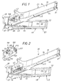
- la figure 1 est une vue en perspective d'une pince de distribution et de sertissage, équipée d'un dispositif d'avance selon un premier mode d'exécution de l'invention ;
- la figure 2 est une vue analogue à la figure 1, le dispositif d'avance comprenant l'insert équipé de la roue dentée étant séparé du reste de la pince, dégageant ainsi l'embrasure de la branche formant magasin de cette pince ;
- la figure 3 est une vue isolée en perspective de la branche formant magasin ;
- la figure 4 est, à échelle supérieure, une vue en coupe transversale suivant le plan IV-IV de la figure 3 ;
- la figure 5 est une vue isolée en perspective de la branche formant outil ;
- la figure 6 est une vue de détail en perspective de la plaquette de sertissage équipant la mâchoire de la branche formant outil ;
- la figure 7 est une vue partielle en coupe de la branche formant magasin de la pince des figures 1 et 2, l'insert seul étant en place dans l'embrasure, sans sa roue dentée d'entraínement ;
- la figure 8 est une vue en perspective de l'insert seul, sans sa roue dentée d'entraínement ;
- la figure 9 est une vue partielle de côté de la branche formant magasin équipée du dispositif d'avance avec l'insert et sa roue dentée d'entraínement en place dans l'embrasure et avec un arraché partiel de la paroi de côté de l'insert autour de la roue dentée d'entraínement permettant de distinguer la coopération de cette roue dentée avec la cartouchière d'accessoires de câblage ;
- la figure 10 est une vue en perspective du dispositif d'avance seul comprenant l'insert équipé de la roue dentée d'entraínement selon une variante d'exécution de cette roue dentée.
- la figure 11 est une vue en perspective, vu de dessus, d'un chargeur associé à la pince ;
- la figure 12 est une vue en perspective, vu de dessous, de ce chargeur ;
- la figure 13 en est, à échelle supérieure, une vue partielle en coupe longitudinale, suivant la ligne XIII-XIII de la figure 11 ;
- la figure 14 en est une vue en coupe transversale, suivant la ligne XIV-XIV de la figure 11 ;
- la figure 15 est une vue en élévation de la pince illustrant la mise en place de ce chargeur ;
- la figure 16 est une vue en élévation illustrant, en position de rangement, la pince suivant l'invention ainsi munie d'un tel chargeur ;
- la figure 17 est une vue en perspective d'un conducteur électrique et d'un accessoire de câblage à poser et sertir sur ce conducteur électrique ;
- les figures 18, 19, 20 sont des vues en perspective qui illustrent la mise en oeuvre de la pince suivant l'invention pour poser et sertir l'accessoire de câblage sur le conducteur électrique ;
- la figure 21 est une vue en perspective qui, analogue à celle de la figure 17, illustre le sertissage obtenu à l'aide de la pince suivant l'invention ;
- la figure 22 est une vue en perspective d'une pince de distribution et de sertissage équipée d'un dispositif d'avance selon un second mode d'exécution de l'invention ;
- la figure 23 est une vue analogue à la figure 22 illustrant un troisième mode d'exécution du dispositif d'avance selon l'invention ;
- la figure 24 est une vue de côté de la branche formant magasin équipée d'un dispositif d'avance selon un quatrième mode d'exécution de l'invention.
Claims (27)
- Pince de distribution et de sertissage pour accessoires (14) de câblage à sertir sur un câble (12), comportant deux branches (20, 22) articulées l'une à l'autre autour d'un axe (19) pour former d'une part des mâchoires de sertissage (27, 28), et d'autre part des poignées de préhension (33, 48), l'une (20) de ces branches formant un magasin et possédant des moyens pour recevoir un chargeur (21) contenant une pluralité d'accessoires de câblage (14) agencés côte à côte en cartouchière (14') pour coulisser perpendiculairement à eux-mêmes le long de ladite branche en vue du rechargement de la pince, de telle manière que l'accessoire de câblage (14) situé en bout de cartouchière (14') soit situé entre les mâchoires de sertissage (27, 28), caractérisée en ce qu'elle comporte un dispositif d'avance (99 ; 119 ; 122 ; 150 ; 200) à actionnement manuel direct réalisant l'entraínement de la cartouchière (14') d'accessoires de câblage (14) pour le rechargement, ce dispositif d'avance comportant une roue dentée d'entraínement (101 ; 120 ; 124 ; 152 ; 202) qui est montée pivotante sur la branche formant magasin (20), autour d'un axe (102 ; 153 ; 203) sensiblement perpendiculaire à la direction longitudinale de coulissement de la cartouchière (14') d'accessoires de câblage (14), et qui engrène la cartouchière (14') d'accessoires de câblage (14) de sorte que l'actionnement manuel de ladite roue dentée (101 ; 120 ; 124 ; 152 ; 202) provoque l'entraínement de la cartouchière (14').
- Pince selon la revendication 1, dans laquelle la roue dentée d'entraínement (101 ; 124) est montée avec un jeu par rapport à la branche formant magasin (20), de telle sorte que la distance entre son axe de rotation (102) et la cartouchière (14') d'accessoires de câblage (14) puisse varier librement entre deux valeurs extrêmes.
- Pince selon l'une des revendications précédentes, dans laquelle la roue dentée d'entraínement (101 ; 120 ; 124 ; 152 ; 202) est portée par un support amovible (100 ; 151 ; 201) rapporté sur la branche formant magasin (20).
- Pince selon la revendication 3, dans laquelle le support amovible est un insert (100 ; 123 ; 151 ; 201) qui est reçu dans une embrasure (40) de la branche formant magasin (20), ouverte sur la cartouchière (14') d'accessoires de câblage (14).
- Pince selon la revendication 4, dans laquelle l'insert (100 ; 123 ; 151 ; 201) est fixé dans l'embrasure (40) de la branche formant magasin (20) par des moyens de fixation amovible (114 ; 116) du type à encliquetage élastique.
- Pince selon l'une des revendications précédentes, dans laquelle la roue dentée d'entraínement (101 ; 120) est au moins en partie accessible extérieurement pour son actionnement manuel direct.
- Pince selon la revendication 6, dans laquelle un cache (100) masque une partie de la roue dentée (101 ; 120), y compris sa zone de prise avec la cartouchière (14') d'accessoires de câblage (14), et présente une ouverture (103) par laquelle une partie de la roue dentée d'entraínement (101 ; 120) fait saillie pour son actionnement manuel.
- Pince selon la revendication 7, prise en dépendance de l'une des revendications 3 à 5, dans laquelle le cache est constitué par le support amovible (100).
- Pince selon la revendication 8, prise en dépendance de la revendication 2, dans laquelle l'axe (102) de la roue dentée d'entraínement (101 ; 120) est matérialisé par deux tourillons latéraux (112) qui sont reçus dans des paliers oblongs (106) ménagés sur le support amovible (100) et ayant un fond (107) et une ouverture d'introduction (108), le jeu des tourillons dans ces paliers étant limité d'une part par le fond (107) desdits paliers et d'autre part par un passage à point dur (109) ménagé au voisinage de l'ouverture d'introduction (108) des paliers (106).
- Pince selon l'une des revendications 6 à 9, prises en dépendance de la revendication 4, dans laquelle l'insert (100) étant creux en forme générale de cornière et constitué d'au moins deux parois d'angle (104, 105), avec une paroi supérieure (104) sensiblement parallèle à la cartouchière (14') d'accessoires de câblage (14), cette paroi supérieure est pourvue intérieurement d'au moins une ramification (110,111) servant au maintien latéral de la roue dentée d'entraínement (101 ; 120).
- Pince selon l'une des revendications 6 à 10, dans laquelle la roue dentée d'entraínement (120) présente un congé de raccordement émoussé (121) entre sa tranche et au moins un de ses deux flancs.
- Pince selon l'une des revendications 1 à 5, dans laquelle la roue dentée d'entraínement (124 ; 152 ; 202) est entraínée en rotation, directement ou indirectement, par une molette d'actionnement (126 ; 154 ; 204) qui est montée sur la branche formant magasin (20) pour tourner autour d'un axe (153 ; 205) sensiblement parallèle à l'axe de rotation (153 ; 203) de la roue dentée d'entraínement (124 ; 152 ; 202).
- Pince selon la revendication 12, dans laquelle la roue dentée d'entraínement (152, 202) est entièrement masquée par un cache (151, 201) tandis que la molette d'actionnement (154, 204) est au moins en partie accessible extérieurement pour sa manipulation par un utilisateur.
- Pince selon la revendication 13, prise en dépendance de l'une des revendications 3 à 5 , dans laquelle le cache est constitué par le support amovible (151 ; 201).
- Pince selon l'une des revendications 13 et 14, dans laquelle le cache (201) masque une partie de la molette d'actionnement (204) et présente une ouverture (207) par laquelle une partie de la molette d'actionnement (204) fait saillie pour son actionnement manuel.
- Pince selon l'une des revendications 13 et 14, dans laquelle la molette d'actionnement (154) est entièrement extérieure au cache (151).
- Pince selon la revendication 16, dans laquelle la molette d'actionnement (154) est déportée latéralement par rapport au plan formé approximativement par les deux branches (20 ; 22) de la pince.
- Pince selon l'une des revendications 12 à 17, dans laquelle l'axe de la molette d'actionnement (126 ; 154) est confondu avec l'axe (153) de la roue dentée d'entraínement (124 ; 152).
- Pince selon la revendication 18, dans laquelle la molette d'actionnement (154) est solidaire en rotation de la roue dentée d'entraínement (152).
- Pince selon la revendication 19, dans laquelle la molette d'actionnement (126) est accolée à la roue dentée d'entraínement (124).
- Pince selon l'une des revendications 12 à 18, dans laquelle la molette d'actionnement (204) entraíne en rotation la roue dentée d'entraínement (202) par l'intermédiaire d'un mécanisme de transmission (206 ; 202).
- Pince selon la revendication 21, dans laquelle le mécanisme de transmission (206 ; 202) est tel qu'il réalise une inversion du sens de rotation de la roue dentée d'entraínement (202) par rapport à celui de la molette d'actionnement (204).
- Pince selon l'une des revendications 21 et 22, dans laquelle le mécanisme de transmission (206 ; 202) est réducteur.
- Pince selon l'une des revendications 21 à 23, dans laquelle le mécanisme de transmission (206 ; 202) est du type à engrenage.
- Pince selon la revendication 24, dans laquelle la molette d'actionnement (204) est solidaire en rotation d'un plateau denté (206) qui engrène directement avec la roue dentée d'entraínement (202).
- Pince selon la revendication 25, prise en dépendance de la revendication 13, dans laquelle le plateau denté intermédiaire (206) est accolé à la molette d'actionnement (204) et présente un diamètre de sommet de dents inférieur au diamètre de la molette d'actionnement (204).
- Dispositif d'avance (99 ; 119 ; 150 ; 200) à actionnement manuel pour une pince de distribution et de sertissage selon l'une des revendications précédentes.
Applications Claiming Priority (2)
| Application Number | Priority Date | Filing Date | Title |
|---|---|---|---|
| FR0003786 | 2000-03-24 | ||
| FR0003786A FR2806842B1 (fr) | 2000-03-24 | 2000-03-24 | Pince de distribution et de sertissage pour des accessoires de cablage a sertir tels que des embouts et dispositif d'avance pour une telle pince |
Publications (3)
| Publication Number | Publication Date |
|---|---|
| EP1137125A2 true EP1137125A2 (fr) | 2001-09-26 |
| EP1137125A3 EP1137125A3 (fr) | 2002-06-12 |
| EP1137125B1 EP1137125B1 (fr) | 2006-05-31 |
Family
ID=8848480
Family Applications (1)
| Application Number | Title | Priority Date | Filing Date |
|---|---|---|---|
| EP20010400597 Expired - Lifetime EP1137125B1 (fr) | 2000-03-24 | 2001-03-07 | Outil de sertissage avec un dispositif d'alimentation |
Country Status (5)
| Country | Link |
|---|---|
| EP (1) | EP1137125B1 (fr) |
| AU (1) | AU777465B2 (fr) |
| BR (1) | BR0101582A (fr) |
| DE (1) | DE60120021T2 (fr) |
| FR (1) | FR2806842B1 (fr) |
Cited By (1)
| Publication number | Priority date | Publication date | Assignee | Title |
|---|---|---|---|---|
| CN116615844A (zh) * | 2020-12-17 | 2023-08-18 | 威德米勒界面有限公司及两合公司 | 挤压钳具 |
Family Cites Families (3)
| Publication number | Priority date | Publication date | Assignee | Title |
|---|---|---|---|---|
| CH346921A (it) * | 1956-08-11 | 1960-06-15 | Cavotex S R L Soc | Utensile per il collegamento delle estremità di due conduttori elettrici, mediante un organo connettore |
| BE625631A (fr) * | 1961-12-04 | |||
| DE4136301A1 (de) * | 1991-11-04 | 1993-05-06 | Weidmueller Interface Gmbh & Co, 4930 Detmold, De | Gurtfoermig miteinander verkettete aderendhuelsen und vorrichtung zu ihrem transport |
-
2000
- 2000-03-24 FR FR0003786A patent/FR2806842B1/fr not_active Expired - Fee Related
-
2001
- 2001-03-07 DE DE2001620021 patent/DE60120021T2/de not_active Expired - Fee Related
- 2001-03-07 EP EP20010400597 patent/EP1137125B1/fr not_active Expired - Lifetime
- 2001-03-23 AU AU29838/01A patent/AU777465B2/en not_active Ceased
- 2001-03-23 BR BR0101582A patent/BR0101582A/pt not_active IP Right Cessation
Cited By (1)
| Publication number | Priority date | Publication date | Assignee | Title |
|---|---|---|---|---|
| CN116615844A (zh) * | 2020-12-17 | 2023-08-18 | 威德米勒界面有限公司及两合公司 | 挤压钳具 |
Also Published As
| Publication number | Publication date |
|---|---|
| EP1137125A3 (fr) | 2002-06-12 |
| DE60120021D1 (de) | 2006-07-06 |
| DE60120021T2 (de) | 2007-01-11 |
| AU2983801A (en) | 2001-09-27 |
| FR2806842B1 (fr) | 2004-03-26 |
| EP1137125B1 (fr) | 2006-05-31 |
| AU777465B2 (en) | 2004-10-21 |
| BR0101582A (pt) | 2001-11-13 |
| FR2806842A1 (fr) | 2001-09-28 |
Similar Documents
| Publication | Publication Date | Title |
|---|---|---|
| EP0327452B1 (fr) | Distributeur à mâchoires de sertissage pour accessoire de câblage à sertir, en particulier embout | |
| EP1496572B1 (fr) | Dispositif de connexion pour câble coaxial | |
| EP2894959B1 (fr) | Tete de coupe rotative a fils et ensemble compose d'une telle tete et d'un arbre d'entrainement de ladite tete | |
| EP1036519B1 (fr) | Distributeur comportant un poussoir ramené dans une position initiale par un organe élastique travaillant en traction | |
| EP1229624B1 (fr) | Accessoire pour goulotte et ensemble comprenant un tel accessoire et une goulotte dont le socle est spécialement adapté audit accessoire | |
| EP1321066A1 (fr) | Dispositif comportant un boítier et un applicateur | |
| CA2720907A1 (fr) | Accessoire pour appareil d'aspiration equipe d'un peigne et d'un organe de degagement de poils et ensemble d'aspiration comportant un tel accessoire | |
| EP0837526A1 (fr) | Borne de connexion automatique, et appareil électrique équipé d'une telle borne de connexion | |
| EP1137125B1 (fr) | Outil de sertissage avec un dispositif d'alimentation | |
| EP0327451B1 (fr) | Distributeur pour accessoire de câblage, en particulier embout | |
| EP0216683B1 (fr) | Outil de pose formant magasin pour de quelconques articles, en particulier pour repères de câblage | |
| EP1865579B1 (fr) | Borne de connexion auto-dénudante et appareillage électrique équipée d'un telle borne | |
| EP0607083B1 (fr) | Accessoire de goulotte et goulotte équipée d'un tel accessoire | |
| EP2006962A1 (fr) | Pince de distribution et de sertissage pour accessoirtes de câblage à sertir sur un câble | |
| FR2615052A1 (fr) | Enrouleur, en particulier pour cable electrique | |
| FR2704169A1 (fr) | Outil à main pour la coupe d'un conducteur électrique isolé, son dénudage et le sertissage d'un embout de câblage sur son extrémité dénudée. | |
| FR2787936A1 (fr) | Dispositif de connexion pour cable coaxial | |
| FR2503771A1 (fr) | Appareil propre a la mise en place de crochets pour elements de couverture, en particulier ardoises | |
| FR3135839A1 (fr) | Bornier électrique muni d’un élément mâle et d’un élément femelle de connexion électrique. | |
| EP0635649A1 (fr) | Ensemble articulé à ressort de rappel, son procédé de montage, et applications, notamment aux boîtiers pour appareillage électrique | |
| EP0692852B1 (fr) | Installation pour la distribution de pâtons de matière adhésive plastique et outil pour la pose desdits pâtons dans des éléments de boítiers de connecteurs électriques | |
| EP1790398A1 (fr) | Piece porte-skis et dispositif pour le portage obtenu | |
| EP4243219B1 (fr) | Prise de courant selon un standard avec contacts de terre latéraux à sécurité renforcée | |
| FR2817672A1 (fr) | Outil a main de sertissage d'embouts comprenant un chargeur d'embouts amovible, et chargeur d'embouts associe | |
| FR2725650A1 (fr) | Outil a main pour le sertissage d'un embout de cablage sur l'extremite denudee d'un conducteur electrique, et, eventuellement, pour le denudage prealable de cette extremite |
Legal Events
| Date | Code | Title | Description |
|---|---|---|---|
| PUAI | Public reference made under article 153(3) epc to a published international application that has entered the european phase |
Free format text: ORIGINAL CODE: 0009012 |
|
| AK | Designated contracting states |
Kind code of ref document: A2 Designated state(s): AT BE CH CY DE DK ES FI FR GB GR IE IT LI LU MC NL PT SE TR |
|
| AX | Request for extension of the european patent |
Free format text: AL;LT;LV;MK;RO;SI |
|
| PUAL | Search report despatched |
Free format text: ORIGINAL CODE: 0009013 |
|
| AK | Designated contracting states |
Kind code of ref document: A3 Designated state(s): AT BE CH CY DE DK ES FI FR GB GR IE IT LI LU MC NL PT SE TR |
|
| AX | Request for extension of the european patent |
Free format text: AL;LT;LV;MK;RO;SI |
|
| RIC1 | Information provided on ipc code assigned before grant |
Free format text: 7H 01R 43/045 A |
|
| 17P | Request for examination filed |
Effective date: 20020705 |
|
| AKX | Designation fees paid |
Designated state(s): BE DE DK GB IT NL |
|
| GRAP | Despatch of communication of intention to grant a patent |
Free format text: ORIGINAL CODE: EPIDOSNIGR1 |
|
| GRAS | Grant fee paid |
Free format text: ORIGINAL CODE: EPIDOSNIGR3 |
|
| GRAA | (expected) grant |
Free format text: ORIGINAL CODE: 0009210 |
|
| AK | Designated contracting states |
Kind code of ref document: B1 Designated state(s): BE DE DK GB IT NL |
|
| PG25 | Lapsed in a contracting state [announced via postgrant information from national office to epo] |
Ref country code: IT Free format text: LAPSE BECAUSE OF FAILURE TO SUBMIT A TRANSLATION OF THE DESCRIPTION OR TO PAY THE FEE WITHIN THE PRESCRIBED TIME-LIMIT;WARNING: LAPSES OF ITALIAN PATENTS WITH EFFECTIVE DATE BEFORE 2007 MAY HAVE OCCURRED AT ANY TIME BEFORE 2007. THE CORRECT EFFECTIVE DATE MAY BE DIFFERENT FROM THE ONE RECORDED. Effective date: 20060531 Ref country code: NL Free format text: LAPSE BECAUSE OF FAILURE TO SUBMIT A TRANSLATION OF THE DESCRIPTION OR TO PAY THE FEE WITHIN THE PRESCRIBED TIME-LIMIT Effective date: 20060531 |
|
| REG | Reference to a national code |
Ref country code: GB Ref legal event code: FG4D Free format text: NOT ENGLISH |
|
| REF | Corresponds to: |
Ref document number: 60120021 Country of ref document: DE Date of ref document: 20060706 Kind code of ref document: P |
|
| RAP2 | Party data changed (patent owner data changed or rights of a patent transferred) |
Owner name: LEGRAND SNC Owner name: LEGRAND FRANCE |
|
| PG25 | Lapsed in a contracting state [announced via postgrant information from national office to epo] |
Ref country code: DK Free format text: LAPSE BECAUSE OF FAILURE TO SUBMIT A TRANSLATION OF THE DESCRIPTION OR TO PAY THE FEE WITHIN THE PRESCRIBED TIME-LIMIT Effective date: 20060831 |
|
| NLT2 | Nl: modifications (of names), taken from the european patent patent bulletin |
Owner name: LEGRAND FRANCE EN LEGRAND SNC Effective date: 20060719 |
|
| NLV1 | Nl: lapsed or annulled due to failure to fulfill the requirements of art. 29p and 29m of the patents act | ||
| GBT | Gb: translation of ep patent filed (gb section 77(6)(a)/1977) |
Effective date: 20061124 |
|
| PLBE | No opposition filed within time limit |
Free format text: ORIGINAL CODE: 0009261 |
|
| STAA | Information on the status of an ep patent application or granted ep patent |
Free format text: STATUS: NO OPPOSITION FILED WITHIN TIME LIMIT |
|
| 26N | No opposition filed |
Effective date: 20070301 |
|
| BERE | Be: lapsed |
Owner name: LEGRAND Effective date: 20070331 Owner name: LEGRAND SNC Effective date: 20070331 |
|
| PG25 | Lapsed in a contracting state [announced via postgrant information from national office to epo] |
Ref country code: BE Free format text: LAPSE BECAUSE OF NON-PAYMENT OF DUE FEES Effective date: 20070331 |
|
| PGFP | Annual fee paid to national office [announced via postgrant information from national office to epo] |
Ref country code: GB Payment date: 20080318 Year of fee payment: 8 Ref country code: IT Payment date: 20080225 Year of fee payment: 8 |
|
| PGFP | Annual fee paid to national office [announced via postgrant information from national office to epo] |
Ref country code: DE Payment date: 20080311 Year of fee payment: 8 |
|
| GBPC | Gb: european patent ceased through non-payment of renewal fee |
Effective date: 20090307 |
|
| PG25 | Lapsed in a contracting state [announced via postgrant information from national office to epo] |
Ref country code: DE Free format text: LAPSE BECAUSE OF NON-PAYMENT OF DUE FEES Effective date: 20091001 |
|
| PG25 | Lapsed in a contracting state [announced via postgrant information from national office to epo] |
Ref country code: GB Free format text: LAPSE BECAUSE OF NON-PAYMENT OF DUE FEES Effective date: 20090307 |
|
| PG25 | Lapsed in a contracting state [announced via postgrant information from national office to epo] |
Ref country code: IT Free format text: LAPSE BECAUSE OF NON-PAYMENT OF DUE FEES Effective date: 20090307 |