Technical Field
This invention relates to an optical recording medium and a method and
apparatus for reproducing the optical recording medium. More particularly, it relates
to an optical recording medium having first and second recording layers and to a
method and apparatus for reproducing the optical recording medium.
Background Art
As a recording medium for a variety of the information, such as audio or video
information, an optical disc, as this recording medium, carrying thereon the recorded
information, adapted to be reproduced using a light beam, is in widespread use. In
such optical disc, it has been proposed to provide for plural recording layers in order
to increase the volume of the recordable information.
Meanwhile, in the optical disc having plural recording layers, proposed so far,
data in the respective recording layers are recorded so as to be sequentially reproduced
from one recording layer to another. That is, in this optical disc, data recorded on one
recording layer is reproduced first and subsequently the data recorded on another
recording layer is reproduced to reproduce the entire data recorded on each recording
layer.
Alternatively, one of plural sectors provided on one recording layer of the
optical disc is reproduced first, and subsequently another one of the sectors, provided
on another one of the recording layers is reproduced.
In the multi-layered optical disc, proposed so far, the recording capacity of the
optical disc is increased by providing plural recording layers. However, the data
recorded on the respective recording layers are reproduced without relevance to one
another. So, the data recorded on the respectively, recording layers are simply
reproduced as the data are recorded in the respective recording layers
Disclosure of the Invention
It is therefore an object of the present invention to provide an optical recording
medium in which first and second reciprocally relevant data, recorded on the first and
second superposed recording layers can be read out readily by a sole readout
mechanism to provide diversified playback information.
An optical recording medium according to the present invention has at least a
first recording layer for recording first data and a second recording layer for recording
second data relevant to the first data. The first and second recording layers are
layered together, the second data being recorded in a location in the second recording
layer in proximity to a location in the first recording layer where the first data relevant
to the second recording layer is recorded. So, the first and second data, recorded on
different recording layers, can be read out sequentially.
The second data is recorded within a range accessible for an objective lens
operating as readout means, adapted for reading out the first or second data of the first
and second recording layers of the recording medium, by shifting the objective lens
from the location of the first recording layer having recorded therein the first data
relevant to the second data. So, the first and second data, relevant to each other,
recorded on different recording layers, can be read out in succession.
The second data used constitutes a sole unitary recording data along with the
first data.
A reproducing apparatus for reproducing data recorded on this optical recording
medium according to the present invention includes readout means forreading out first
and second data, relevant to each other, recorded in the first and second recording
layers superposed on the optical recording medium, and reproducing means for
generating playback signals based on the first and second data read out by this readout
means. A controller manages control to read out the first and second data recorded on
the first and second recording layers and to synthesize the first and second data to
output the synthesized first and second data.
According to the present invention, respective data relevant to each other,
recorded in the plural layers of the optical recording medium, are read out by readout
means, such as an optical pickup, provided with an objective lens, the data so
generated being read out alternately and synthesized for reproduction to provide for
variegated data reproduction.
Other objects, features and advantages of the present invention will become
more apparent from the following detailed description of the present invention and the
claims.
Brief Description of the Drawings
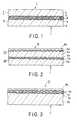
Fig.1 is a cross-sectional view showing an embodiment of an optical disc of the
present invention.
Fig.2 is a cross-sectional view showing another embodiment of an optical disc
of the present invention.
Fig.3 is a cross-sectional view showing still another embodiment of an optical
disc of the present invention.
Fig.4 shows a typical disposition of a loudspeaker for audio signals recorded on
an optical disc of the present invention.
Figs.5A and 5B show a data structure of first and second data recorded on the
first and second recording layers of the optical disc.
Fig.6 is a schematically shows the state of recording of data on the first and
second recording layers of the optical disc.
Fig.7 is a block diagram showing a reproducing apparatus for reproducing an
optical disc according to the present invention.
Fig.8 is a block diagram showing a reproducing apparatus for the optical disc
according to the present invention.
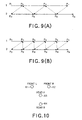
Figs.9A and 9B show switching timing in reproducing the first and second data
Fig.10 shows another typical disposition of a loudspeaker for audio signals
recorded on an optical disc of the present invention.
Fig.11 shows another typical data structure of first and second data recorded on
an optical disc of the present invention.
Fig.12 shows still another typical disposition of a loudspeaker for audio signals
recorded on an optical disc of the present invention.
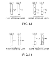
Fig.13 shows still another typical data structure of first and second data
recorded on an optical disc of the present invention.
Fig.14 shows yet another typical data structure of first and second data recorded
on an optical disc of the present invention.
Best mode for Carrying out the Invention
Referring to the drawings, specified embodiments of an optical recording
medium and a method and apparatus for reproducing the optical recording medium are
explained in detail.
The optical recording medium according to the present invention is constructed
e.g., as an optical disc. The optical disc, to which the present invention is applied, is
configured as shown for example in Figs.1 to 3.
An optical disc 1, shown in Fig.1, includes a first recording medium 4,
comprised of a first recording layer 3 formed on one surface of a first substrate 2,
exhibiting light transmission properties, and a second recording medium 7, comprised
of a second recording layer 6 formed on one surface of a second substrate 5, exhibiting
light transmission properties. The first recording medium 4 and the second recording
medium 6 are bonded together via a light-transmitting adhesive layer 8 with the sides
thereof carrying the first and second recording layers facing each other. The so-constructed
optical disc 1 is made up of the first and second recording layers 3, 6
layered together via adhesive layer 8. Meanwhile, the adhesive layer 8 is of such a
sufficient thickness that neither the first recording layer 3 nor the second recording
layer 6 is disposed within the depth of focus of a light beam L which will be explained
subsequently. The layering in the context of the present specification denotes such a
state in which the first recording layer 3 and the second recording layer 6 run parallel
to each other, with neither the first recording layer 3 nor the second recording layer 6
being disposed within the depth of focus of the illuminating light beam L.
The first recording layer 3 of the optical disc 1 according to the present
invention is formed as a semi-transmitting layer so that light beam L is illuminated
onto the second recording layer 6 via the first recording layer 3 from the same
direction as the light beam illuminating direction to the first recording layer 3 to
reproduce data recorded on the second recording layer 6 based on the light beam
reflected back from the second recording layer 6.
In the present optical disc 1, switching between reproduction of data recorded
on the first recording layer 3 and that of data recorded on the second recording layer
6 is by changing the focal point position of the light beam L illuminated on the optical
disc 1 between the first recording layer 3 and the second recording layer 6.
An optical disc 1a, shown in Fig.2, is made up of a first recording medium 4a,
comprised of a first recording layer 3a formed on one surface of a first substrate 2a,
exhibiting light transmission characteristics, and a second recording medium 7a,
comprised of a second recording layer 6a formed on one surface of a second substrate
5a, exhibiting light transmission characteristics. The first recording medium 4a and
the second recording medium 7a are bonded together via a light-transmitting adhesive
layer 8a. The optical disc 1a shown in Fig.2 is comprised of the first and second
recording mediums 4a, 7a bonded together side-by-side so that the second substrate
5a will be located on the first recording layer 3a. The first recording layer 3a and the
second recording layer 6a are separated from each other by the adhesive layer 8a so
that the layers 3a, 6a are not located within the depth of focus of the light beam L
which will be explained subsequently.
In the above-described optical disc 1a, data recorded on the first and second
recording layers 3a, 6a are reproduced based on a light beam L illuminated from the
substrate 2a of the first recording medium 4a and reflected by the first recording layer
3a and also based on a light beam illuminated on the second recording layer 6a via the
first recording layer 3a and reflected by the second recording layer 6a of the light
illuminated on the second recording layer 6a through the first recording layer 3a. In
this optical disc 1a, switching between reproduction of data recorded on the first
recording layer 3a and that of data recorded on the second recording layer 6a is by
changing the focal point position of the light beam L illuminated on the optical disc 1
between the first recording layer 3a and the second recording layer 6a. A n
optical disc 1b shown in Fig.3 includes a substrate 2b of light-transmitting synthetic
resin, such as polycarbonate resin or glass. On one surface of the substrate 2b is
formed a first recording layer 3b. This first recording layer 3b is formed as a semitransparent
film transmitting a pre-set amount of the light beam L illuminated from the
substrate 2b and reflecting its pre-set amount. On the first recording layer 3b is layered
a second recording layer 6b via an intermediate layer 10 formed of a light-transmitting
UV light curable resin. The intermediate layer 10 is formed to a pre-set thickness
since it performs the role of optically isolating the first recording layer 3b and the
second recording layer 6b from each other so that these layers will not be located
within the depth of focus of the objective lens converging and illuminating the light
beam L on the recording layers 3b, 6b. On the second recording layer 6b is formed a
protective layer 9b of, for example, UV light curable resin, for protecting the surface
of the recording layer 6b.
In the above-described optical disc 1b, data recorded on the first and second
recording layers 3b, 6b are reproduced by detecting the light beam illuminated from
the substrate 2b and reflected by the first recording layer 3b and also by detecting the
light beam illuminated on the second recording layer 6b through the first recording
layer 3b and the light beam illuminated on the second recording layer 6b via the first
recording layer 3b and reflected by the second recording layer 6b. In this optical disc
1b, switching between reproduction of data recorded on the first recording layer 3b
and that of data recorded on the second recording layer 6b again is by changing the
focal point position of the light beam L illuminated on the optical disc 1 between the
first recording layer 3b and the second recording layer 6b.
In the optical discs 1, 1a, 1b, according to the present invention, first data and
second data, relevant to each other, are recorded on the first recording layers 3, 3a, 3b
and the second recording layers 6, 6a, 6b. The first and second data may also be multi-channel
audio data synthesized together to give unit recording data, for example,
multi-channel audio data which enables surround reproduction.
The multi-channel audio data are left and right front channel data input to left
and right front speakers 11, 12 arranged ahead of an acoustic space forwardly of a
listener, and left and right rear channel data input to left and right rear speakers 13,14
arranged in back of an acoustic space rearwardly of the listener, as shown in Fig.4.
The left and right channel data are recorded as first data on the first recording
layers 3, 3a, 3b, whilst the left and right rear channel data are recorded as first data on
the second recording layers 6, 6a, 6b. The first data may be handled as meaningful
reproduced main data because the first data reproduced alone enable usual two-channel
stereo reproduction. On the other hand, the second data may be handled as
sub-data relevant to the main data because it can be reproduced with the first data to
enable so-called multi-channel audio reproduction.
It is noted that left and right front channel data Lf, Rf, recorded as the first data
on the first recording layers 3, 3a, 3b, are quantized as 16-bit data for each of the left
and right channel data, as shown in Fig.5A. Moreover, left and right rear channel data
Lb, Rb, recorded as the second data on the second recording layer 6, are quantized as
16-bit data for each of the left and right channel data, as shown in Fig.5B.
Taking the optical disc 1, shown in Fig.1, as an example, the second data
recorded on the second recording layers 6, 6a, 6b are recorded at B1, B2, ··· locations
of the second recording layer 6 in the vicinity of A1, A2, ··· locations of the first
recording layer 3 in which are recorded first data relevant to the second data. In
particular, the second data is recorded within a range D1 accessible for the objective
lens 15 of the optical pickup, adapted for reading out the first and second data of the
first and second recording mediums 3,6 of the optical disc 1, on shifting the objective
lens from the positions A1, A2 in the first recording layer 3, in which are recorded first
data relevant to the second data, in a direction indicated by arrow X in Fig.6
perpendicular to the recording tracks formed in the first and second recording layers
3, 6. This range Di is a range that may be accessed within the field of view of the
objective lens 15 without performing sled feed of the optical pickup in a direction
perpendicular to the recording track, by a pickup feed unit, not shown, and is
specifically a range of, for example, approximately 200 µm. More specifically, the
first and second data are recorded so that the leading ends of the areas of recording of
the first and second data in the first and second recording layers 3 and 6 will be within
a range of approximately 200 µm from each other. For example, if the first and
second data are recorded in the first and second recording layers 3, 6 in the standard
format for the Compact Disc (CD), and if the range D1 which permits accessing on
shifting the objective lens 15 within its field of view, the recording start positions of
data of the first and second data are set so as to be within 60 concentrically or spirally
extending recording tracks in the first and second recording layers 3 and 6.
The state of recording the first and second data, relevant to each other, in the
first and second recording layers 3, 3a, 3b, 6, 6a, 6b, is now explained. This recording
is explained with reference to a recording device 21 shown in Fig.1. Of course, the
present invention can be applied to optical discs 1a, 1b shown in Figs.2 and 3.
The recording device 21 shown in Fig.7 includes a first input terminal 22, fed
with the first audio signals corresponding to the first data recorded on the first
recording layer 3 of the optical disc 1, and a second input terminal 122, fed with the
second audio signals corresponding to the second data recorded on the second
recording layer 6.
The first and second audio signals, fed to the first and second input terminals
22,122, are analog audio signals, relevant to each other, and which form multi-channel
audio signals which may be synthesized to enable the aforementioned surround
reproduction. That is, the analog audio signals, fed to the focussing servo input
terminal s 22, 122, are converted into left and right front channel data Lf, Rf and left
and right rear channel data Lb, Rb, making up relevant audio data of front and rear
four channels by signal processing, as later explained, and which are subjected to
sampling at the sampling frequency of 44.1 kHz and 16-bit quantization. The front
channel data Lf, Rf and the rear channel data Lb, Rb may be said to be relevant data
at the same time point on the time axis.
It may be seen from above that the first input terminal 22 is fed with first audio
signals, corresponding to the left and right front channel data Lf, Rf, whilst the second
input terminal 122 is fed with the second audio signals corresponding to the left and
right rear channel data Lb, Rb.
The first audio signals, fed to the first input terminal 22, are amplified by a first
line amplifier 23, and thence sent to a first adder 25 for addition of a dither as a small
random noise from a dither generator 24. From the first audio signals, added to with
the dither by the first adder 25, only a band 20 kHz or less is taken out by a first LPF
26, and thence routed to a first sampling circuit 27, which then applies sampling
processing at a sampling frequency of 44.1 kHz to a filtered output from the first LPF
26. The sampling data from the first sampling circuit 27 is converted by a first A/D
converter 28 into 16-bit digital audio data.
In similar manner, the second audio signals, fed to the second input terminal
122, are amplified by a second line amplifier 123, and thence sent to a second adder
125 for addition of a dither as a small random noise from the1 dither generator 24.
From the second audio signals, added to with the dither by the second adder 25, only
a band 20 kHz or less is taken out by a second LPF 26, and thence routed to a second
sampling circuit 127, which then applies sampling processing at a sampling frequency
of 44.1 kHz to a filtered output from the second LPF 126. The sampling data from the
second sampling circuit 127 is converted by a second A/D converter 128 into 16-bit
digital audio data.
The first digital data, converted into 16-bit digital audio data derived from the
first audio signals output by the first A/D converter 28, are stored in a first buffer
memory 29. The first audio data, read out from the first buffer memory 29, is routed
to a first error correction encoding circuit 30 where it is encoded by the combination
of cross-interleaving and four-order Reed-Solomon code employing an algorithm of
CIRC (Cross Interleave Reed Solomon Code) used in a CD. The encoded data from
the first error correction encoding circuit 30 is EFMed (eight-to-fourteen modulated)
by a first modulation circuit 31 and processed by a first recording processing circuit
32 so as to be recorded by the optical pickup on the first recording layer 3 of the
optical disc 1.
The second digital data, converted into 16-bit digital audio data derived from
the second audio signals output from the second A/D converter 128, is stored in a
second buffer memory 129. The second audio data, read out from the second buffer
memory 129, is routed to a second error correction encoding circuit 130 where it is
encoded by the combination of cross-interleaving and four-order Reed-Solomon code
employing an algorithm of CIRC(Cross Interleave Reed Solomon Code) used in a CD.
The encoded data from the second error correction encoding circuit 130 is EFMed
(eight-to-fourteen modulated) by a second modulation circuit 131 and processed by
a second recording processing circuit 132 so as to be recorded by the optical pickup
on the second recording layer 6 of the optical disc 1.
The first digital data recorded on the first recording layer 3 and the second
digital data recorded on the second recording layer 6 are recorded with time axis
coincidence relative to each other.
In a manner contrary to the above-described embodiment, the left and right
front channel data Lf, Rf derived from the first audio signals may be recorded in the
second recording layer 6, with the left and right rear channel data Lb, Rb derived from
the second audio signals being then recorded on the first recording layer 3.
A reproducing apparatus for reproducing an optical disc 1, having recorded
thereon the first and second data pertinent to the first and second recording layers 3,
6, respectively, is now explained.
Referring to Fig.8, the reproducing device includes an optical pickup 41 and a
signal readout unit 42 for reading out first and second data recorded in the first and
second recording layers 3, 6 of the optical disc 1, a first buffer memory 43 for storing
the first data recorded in the first recording layer 3 and read out by the optical pickup
41, a second buffer memory 44 for storing the second data recorded in the second
recording layer 6, a buffer management unit 46 for supervising and controlling the
writing and readout on or from the first and second buffer memories 43, 44, a
multiplexer 45 for adding or subtracting outputs read out from the first and second
buffer memories 43, 44, and a servo circuit 48 for focussing and tracking controlling
the objective lens of the objective lens of the optical pickup 41 to focus the light beam
radiated from the optical pickup 41 or to cause the light beam rdiated from the optical
pickup 41 to follow the target recording track on the optical disc 1. This servo circuit
48 includes a switching unit 49 for switching the focussing position of the light beam
radiated from the optical pickup 41 in order to converge the light beam by an objective
lens of the optical pickup 41 to focus the light beam on the first or second recording
layer 3, 6. For switching, that is shifting, the focussing position of the light beam
radiated from the optical pickup 41 between the first recording layer 3 and the second
recording layer 6, the objective lens of the optical pickup 41 is moved along the optical
axis of the objective lens. The reproducing apparatus includes a spindle motor 50 for
causing the rotation of the optical disc 1 e.g., at a CLV under control by the servo
circuit 48.
The reproducing apparatus 40 includes a controller (CPU) 47 for determining,
under instructions from a user, whether the audio data recorded on the first and second
recording layers 3, 6 of the optical disc 1 is to be reproduced, whether audio data
recorded on the first and second recording layers 3, 6 of the optical disc 1 are
synthesized and reproduced or whether an optical disc such as a conventional optical
disc is to be reproduced, depending on the configuration of the loaded disc, based on
instructions from a user, and for controlling the servo circuit 48, switching unit 49,
signal read-out unit 42 and the buffer management unit 46, based on the result of
decision. To this controller 47 is connected an operating unit provided with plural
operating switches, not shown, for a user to input the aforementioned instructions. In
place of the aforementioned instructions from the user, control signals may also be
input to the controller 47 from an external equipment, such as a personal computer,
not shown.
In this reproducing apparatus 40, the audio data read out from the first and
second recording layers 3, 6 are adapted for being stored in the buffer memories 43,
44. Alternatively, these audio data may also be stored in a sole common buffer
memory.
In this reproducing apparatus 40, the first and second digital data, read out by
the optical pickup 41 from the first and/or second recording layers 3, 6, are routed to
the signal read-out unit 42. Based on the control signal from the servo circuit 48 or
the switching unit 49, the optical pickup 41 switches the focussing position of the light
beam on the first recording layer 3 or on the second recording layer 6 for controlling
the light beam focussing state to follow surface shaking of the optical disc 1 and for
controlling the light beam to follow the recording tracks of the first and second
recording layers 3, 6.
The signal read-out unit 42 performs pre-set playback signal processing, such
as RF processing, demodulation or error correction processing, on the first and second
digital data read out from first or second recording layer 3 or 6, as output signal from
the optical pickup 41, to route output data derived from the first digital data and output
data derived from the second digital data to the first buffer memory 43 and to the
second buffer memory 44, respectively.
The first buffer memory 43 is a playback memory for first digital data, read out
from the first recording layer 3, whilst the second buffer memory 44 is a playback
memory for second digital data, read out from the second recording layer 6. The first
buffer memory 43 or the second buffer memory 44 is controlled and supervised by the
buffer management unit 46 as to data writing from the signal read-out unit 42 or data
readout from the buffer memory 44.
Next, the operation of the reproducing apparatus 40 shown in Fig.8 is explained
in detail.
If a playback mode selection button of an operating unit, not shown, provided
on the reproduction apparatus 40 and which is connected to the controller 47, is acted
on by the user, and the playback mode of multiplexing and reproducing the first and
second data recorded on the first and second recording layers 3,6, is selected, the data
is reproduced by the following operations: If the playback mode of multiplexing and
reproducing the data is selected, the controller (CPU) 47 decides to multiplex and
reproduce the first and second data read out from the first and second recording layers
3, 6 of the optical disc 1. If the multiplexing reproduction is selected, the optical
pickup 41 is controlled by the servo circuit 48 or the switching unit 49 so that the
focussing point of the playback light beam will be switched to the first recording layer
3 or to the second recording layer 6 based on the control signal supplied from the
controller 47. The timing of switching of the focussing point of the light beam to the
first recording layer 3 or to the second recording layer 6 is such that, if second data
recorded on the second recording layer 6 is to be reproduced after reproducing the first
data recorded on the first recording layer 3, the focussing point of the light beam is
shifted to a location temporally ahead of a replay end point of the first data of the first
recording layer 3 to start the reproduction of the second data, the second data is
reproduced to a location temporally posterior to a replay end point of the audio data
of the first recording layer 3 and the focussing point of the light beam is shifted to a
location on the first recording layer 3 next to the last readout point to reproduce the
first data.
That is, if, after reproducing the first data from a point P11 to a point P12 on
the first recording layer 3, the focussing point of the light beam is to be shifted to the
second recording layer 6, as shown in Fig.9A, the second data is started to be
reproduced from a point P21 temporally retrograding from a replay end point P12 of
the first recording layer 3. After reproducing the second data to a point P22
temporally posterior from the replay end point P12 of the first recording layer 3, the
focussing point of the light beam is shifted to a point P12 on the first recording layer
3 to start reproducing the first data. Data reproduction of the first data as from the
point P12 of the first recording layer 3 is continued up to a point P13 temporally
posterior to the replay end point P22 of the second recording layer 6. If the light beam
focussing point is to be shifted to the second recording layer 6, the first data is
reproduced at a temporally previous replay end point P13 of the second recording
layer 6 up to a point P23 temporally posterior from the replay end point P13 of the
first recording layer 3.
The first and second data, read out from the first recording layer 3 and the
second recording layer 6 at the replay timing shown in Fig.9A, are routed to the signal
read-out unit 42 where replay signal processing occurs in accordance with the
aforementioned timing. When outputting readout signals read out from the first
recording layer 3 or the second recording layer 6, the signal read-out unit 42 outputs
identification signals, pre-recorded on the first recording layer 3 and the second
recording layer 6 for indicating the recording layers 3,6, respectively, to the controller
47. The controller 47 then discriminates, based on the furnished identification signals,
whether the output data from the signal read-out unit 42 has been read out from the
first recording layer 3 or from the second recording layer 6, and controls the data
writing or readout timing to or from the first and second buffer memories 43, 44
through the buffer management unit 46.
The data writing timing to the first and second buffer memories 43, 44 is the
same as the replay timing shown in Fig.9A or the readout timing in the signal read-out
unit 42. On the other hand, the data readout timing from the first and second buffer
memories 43, 44 is such that, after a pre-set amount of data has been written in one of
the first and second buffer memories 43,44, the data readout is started from the other
of the first and second buffer memories 43,44. Theoretically, the optical disc 1 is run
in rotation at an rpm not less than double the standard rpm to read out the first and
second data from the first recording layer 3 and the second recording layer 6 of the
optical disc 1, at a speed not less than the standard speed, to write data in the first and
second buffer memories 43, 44. The first and second data, recorded on the first and
second recording layers 3,6, are read out from the respective buffer memories 43,44
and output at an output terminal 51 after multiplexing by a multiplexer 45. For reading
out the first recording layer 3 and the second recording layer 6 at a haploid speed, that
is at a standard speed prescribed in the reference standard manual, data readout from
the optical disc 1 needs to be performed at a speed twice the aforementioned standard
speed, if the switching time for reproduction timing of the first and second recording
layers 3, 6 is discounted. In actuality, the spindle motor 50 is desirably run in rotation
at a quadrupled or higher speed to read out data from the optical disc 1.
Meanwhile, the timing of switching the focussing position of the replay light
beam, radiated from the optical pickup 41, between the first recording layer 3 and the
second recording layer 6, under control by the controller 47, may be such timing as is
shown in Fig.9B. If data is reproduced from the point P11 up to the point P12 on the
first recording layer 3, and reproduction is to be shifted to the second recording layer
6, the focussing point of the replay light beam reverts to a point temporally previous
to the replay end point P12 on the first recording layer 3 to start reproduction of the
second data of the second recording layer 6 as from the point P21. After reproducing
up to a point P22 of the same timing on the time axis as the replay end point of the
first recording layer 3, the focussing point of the replay light beam is shifted to the
point P12 on the first recording layer 3 to start reproduction of the first data of the first
recording layer 3 as from the point P12. The first data continues to be reproduced from
the point P12 of the first recording layer 3 up to the point P13 temporally posterior to
the replay end point P22 of the second recording layer 6. If reproduction is to be
shifted to the second recording layer 6, the focussing position of the replay light beam
reverts to the replay end time point P22 of the second recording layer 6 to reproduce
the second data of the second recording layer 6 up to the point P23, which is the same
time point as the replay end time point P13 of the first recording layer 3.
The signal read from the first recording layer 3 and the second recording layer
6 in the replay timing shown in Fig.9B are routed to the signal read-out unit 42 where
replay signal processing is carried out in accordance with the aforementioned timing.
By reproducing the first and second data, relevant to each other, recorded on
the first and second recording layers 3, 6 of the optical disc 1, by the reproducing
apparatus 40, shown in Fig.8, and by synthesizing the reproduced data by the
multiplexer 45, it is possible to achieve stereo reproduction of four channels
comprising left and right front channel data and left and right rear channel data Lb, Rb.
The first and second data, recorded on the first and second recording layers 3,
6 of the optical disc 1, and which are related to each other to constitute sole unit
recording data, are recorded in a tracking control range within the field of view of the
objective lens, without relying upon the sled feed of the optical pickup 41 by a pickup
feed unit, not shown, in a direction along the radius of the optical disc 1, that is in a
direction perpendicular to the recording track. So, it is possible to reduce the amount
of movement of the optical pickup 41 in a direction perpendicular to the recording
track to reproduce and synthesize the first and second data sequentially smoothly.
If, in the reproducing apparatus 40, shown in Fig.8, a playback mode selection
button of an operating unit, not shown, provided in the apparatus 40, is acted on by the
user, and the user's command is to reproduce only the first data recorded on the first
recording layer 3 of the optical disc 1, the operating unit 47 decides reproduction only
of the first data from the first recording layer 3. At this time, the optical pickup 41 is
controlled by the servo circuit 48 and the switching unit 49 so that the light beam is
focussed on the first recording layer 3 of the optical disc rotationally driven by the
spindle motor 50 to scan only the first recording layer 3. If the optical pickup 41 is
controlled to scan the first recording layer 3, the return light beam, reflected only from
the first recording layer 3, is received by a photodetector of the optical pickup 41, an
output signal of which is routed to the signal read-out unit 42 where signal processing
is performed on the audio data recorded on the first recording layer 3. The first data
recorded on the first recording layer 3 detected by the signal read-out unit 42 is
processed in a pre-set fashion and written in the first buffer memory 43 at a pre-set
timing under control by the buffer management unit 46. The data is then read out from
the first buffer memory 43 and output via multiplexer 45 at the output terminal 51.
The first data, read out from the first recording layer 3, is converted via an error
interpolator, an LPF and a D/A converter, all not shown, connected to the output
terminal 51, into analog audio signals, which are output.
If the replay mode selection button of an operating unit, not shown, provided
in the reproducing apparatus 40, is acted on by the operator, and the replay mode of
reproducing only the second data recorded on the second recording layer 6 of the
optical disc 1 is selected, the processing similar to that in case of the selection of the
reproducing mode of reproducing only the first recording layer 3 is performed to read
out the second data recorded in the second recording layer 6, and the data so read out
is output as the reproduced second data at the output terminal 51. Alternatively, the
second data may be converted into and output as analog audio signals, as in the case
of the aforementioned first data.
Meanwhile, if the optical disc 1 of the present invention is arranged as shown
for example in Fig.3, in which the second recording layer 6 of the focussing servo
recording layers 3, 6, in which to record left and right front channel data Lf, Rf
corresponding to the first audio signals, is of a reflectance which permits reproduction
by a reproducing apparatus capable of reproducing a routine CD, and recording
thereon is made in a format satisfying the CD format, the optical disc 1b can be
reproduced in the reproducing apparatus designed to reproduce the routine CD. Four-channel
stereo reproduction can be realized by using a reproducing apparatus
configured as shown in Fig.8 for reproducing the first and second recording layers 3b,
6b and by synthesizing and reproducing left and right front channel data Lf, Rf and left
and right rear channel data Lb, Rb.
Of the four-channel audio data, recorded in the optical disc 1, left and right
front channel data Lf, Rf are recorded as first data in the first recording layer 3, while
left and right rear channel data Lb, Rb are recorded as second data in the second
recording layer 6. Alternatively, a variety of data relevant to one another to constitute
sole unit recording data may be recorded in the focussing servo recording layers 3, 6.
If the audio data recorded on the optical disc 1 is multi-channel data comprised
of left and right front channel data Lf, Rf, input to the left and right front speakers 61,
62, arranged on the front side of an acoustic space, rear channel data B input to a rear
speaker 63 arranged on the rear side and a high channel data H input to an upper
speaker 64 arranged above the listener's head, as shown in Fig.10, it is sufficient if the
front channel data Lf, Rf are recorded as first data in the first recording layer 3 and the
rear channel data B and the upper channel data H are recorded as second data in the
second recording layer 6.
If the multi-channel data is recorded in a split fashion in the first and second
recording layers 3, 6 and only the first data recorded in the first recording layer 3 is
reproduced, two-channel stereo reproduction by the left and right front speakers 61,
62 can be performed, whereas, if the first and second data recorded in the first and
second recording layers 3, 6 are synthesized and reproduced, multi-channel stereo
reproduction can be performed using the left and right front speakers 61, 62, rear
speaker 63 and the upper speaker 64.
On the other hand, if the audio data recorded on the optical disc 1 is the multi-channel
data made up of left and right front channel data Lf, Rf input to the left and
right front speakers 71, 72 arranged forwardly of an acoustic space, rear channel data
Lb, Rb input to the left and right rear speakers 73, 74, arranged at back of the acoustic
space, and the upper channel data H input to the upper speaker 75, arranged overhead,
as shown in Fig.12, the front channel data Lf, Rf are recorded as first data in the first
recording layer 3, whilst the rear channel data Lb, Rb and the upper channel data H are
recorded as second data in the second recording layer 6, as shown in Fig.13. At this
time, the rear channel data Lb, Rb and the upper channel data H are recorded in upper
12 bits and in lower 4 bits of the quantized 16-bit second data of each of the left and
right channels recorded in the second recording layer 6, respectively.
Referring to Fig.14, it is also possible to record 16-bit front channel data Lf, Rf
as first data in the first recording layer 3, and to record the rear channel data Lb, Rb,
data of audio signals of the mid frequency range and data of the audio signals in the
low frequency range, in upper 10 bits, mid 5 bits and in the lower one bit of the
quantized 16-bit second data of each of the left and right channels recorded in the
second recording layer 6.
In recording the first and second data as shown in Figs.13 and 14, the first and
second data are recorded in a range that can be accessed by movement in the field of
view of the objective lens of the optical pickup 41.
By recording data relevant to one another to constitute a unit recording data in
the first and second recording layers or in three or more recording layers, in a split
fashion, it is possible not only to increase the recording capacity on a disc but also to
reproduce the information of variable sorts.
The first and second data recorded in the first and second recording layers of
the optical disc may constitute, in addition to the aforementioned multi-channel audio
data, data relevant to one another or a sole recording data unit, as now explained.
For example, there are occasions where the first data is upper order bits of the
quantized data, with the second data then being lower order bits of the quantized data,
the first data is audio data, with the second data being text data relevant to this audio
data, such as lyric, or image data, the first data is image data, with the second data then
being data relevant to the image data, such as title or synopsis data, and so on. In these
cases, the audio data as the first data or the image data, reproduced alone, may be
handled as meaningful data, whilst the second data, such as text or title data, may also
be handled as sub-data relevant to the first or main data. Of course, the combination
of the first and second data may be other than that explained above only by way of
illustration.
If, in recording the first and second data, relevant to each other, in the first and
second recording layers of the optical disc, the first and second data are recorded with
the same format, inclusive of the recording density, in the recording tracks formed at
approximately equal positions of the first and second recording layers, it is sufficient
to cause the movement of the objective lens in a direction parallel to the optical axis
of the objective lens along the direction of thickness of the optical disc, that is in the
focussing direction, when the first and second data recorded in the first and second
recording layers are read out in a switching fashion by the sole optical pickup, thus
assuring facilitated control of the optical pickup.
In the above-described embodiment, the optical recording medium is an optical
disc, however, the optical recording medium may also be a card type recording
medium, such as an optical card.
Industrial Applicability
According to the present invention, as described above, the second data
recorded in the second recording layer of first and second recording layers layered
together is recorded in a location adjacent to a location of the first recording layer
where the first data relevant to the second data is recorded. So, the movement range
of readout means, such as optical pickup, for reading out the first and second data
recorded in different recording layers can be diminished and hence the first and second
data can be read out smoothly in a switching fashion to reduce the size of the buffer
memory provided in the reproducing apparatus to realize saving in power
consumption.
Moreover, since the relevant data can be recorded in plural recording layers,
replay signals of variable configurations can be produced by suitably synthesizing data
read out from the respective recording layers