EP1136947A2 - Information processing method - Google Patents
Information processing method Download PDFInfo
- Publication number
- EP1136947A2 EP1136947A2 EP01302302A EP01302302A EP1136947A2 EP 1136947 A2 EP1136947 A2 EP 1136947A2 EP 01302302 A EP01302302 A EP 01302302A EP 01302302 A EP01302302 A EP 01302302A EP 1136947 A2 EP1136947 A2 EP 1136947A2
- Authority
- EP
- European Patent Office
- Prior art keywords
- image information
- pattern image
- pattern
- prepared
- synthetic
- Prior art date
- Legal status (The legal status is an assumption and is not a legal conclusion. Google has not performed a legal analysis and makes no representation as to the accuracy of the status listed.)
- Granted
Links
Images







Classifications
-
- H—ELECTRICITY
- H04—ELECTRIC COMMUNICATION TECHNIQUE
- H04N—PICTORIAL COMMUNICATION, e.g. TELEVISION
- H04N5/00—Details of television systems
- H04N5/76—Television signal recording
- H04N5/91—Television signal processing therefor
- H04N5/913—Television signal processing therefor for scrambling ; for copy protection
-
- G—PHYSICS
- G06—COMPUTING OR CALCULATING; COUNTING
- G06T—IMAGE DATA PROCESSING OR GENERATION, IN GENERAL
- G06T1/00—General purpose image data processing
- G06T1/0021—Image watermarking
- G06T1/0028—Adaptive watermarking, e.g. Human Visual System [HVS]-based watermarking
-
- G—PHYSICS
- G06—COMPUTING OR CALCULATING; COUNTING
- G06T—IMAGE DATA PROCESSING OR GENERATION, IN GENERAL
- G06T2201/00—General purpose image data processing
- G06T2201/005—Image watermarking
- G06T2201/0051—Embedding of the watermark in the spatial domain
Definitions
- the present invention relates to an information processing method for synthesizing main image information (which represents a portrait face image, for example) with sub image information (which is additional information, such as security information) and recording resultant synthetic image on a recording medium.
- the information processing method is also for sensing the sub image information from the recorded synthetic information.
- Jpn. Pat. Appln. KOKAI Publication No. 9-248935 discloses a method for embedding a monochromatic binary image in a color image, using color sensitivity.
- Jpn. Pat. Appln. KOKAI Publication No. 6-10190 discloses a method for preventing forgery and modification of an ID card.
- the ID card is overlaid with either a transparent film having a unique fine-line pattern or mesh pattern, or a lenticular film having a predetermined frequency. Since moiré patterns generated then are different depending upon the films laid on the ID card, the forgery and modification are prevented.
- the sub image information embedded in synthetic image information is reproduced for verification by reading the synthetic image information by use of high-resolution read means and reproducing the sub image information from the read image information. Since the high-resolution read means (scanner) is required for reading the synthetic image formation, the verification is not easy.
- the embedded sub image picture is reproduced by laying a sheet-like mask on the synthetic image information with high accuracy.
- the sub image information is reproduced by accurately positioning the sheet-like mask and the synthetic image information with reference to each other. In other words, extremely high accuracy is needed when the synthetic image information is recorded and when the sub image information is reproduced. Since easy reproduction of the sub image information is not enabled, easy verification is not possible.
- sub image information used for verification is prepared in a state where it can be visually perceived by a human being. This means that the storage position of the information that is essentially important to the verification may be easily known. Hence, the method of the reference is not reliable in terms of security.
- the conventional information processing method has the problem that the easy verification based on the sub image information for security and the reliable security for verification are incompatible.
- an object of the present invention is to provide an information processing method which enables sub image information to be synthesized with main image information that is recognizable to the naked eye of a human being, in such a manner that the synthesis itself is executed in a state that is not recognizable to the naked eye of the human being, and which enables the sub image information to be easily sensed in a simple way, thereby attaining easy verification based on the sub image information.
- the present invention provides an information processing method comprising: a first step of preparing main image information that is recognizable to the naked eye of a human being; a second step of preparing pattern image information; a third step of executing color difference modulation processing for the pattern image information prepared in the second step in accordance with a predetermined color difference modulation amount, and superimposing the pattern image information, which has been modulated in color difference by the color difference modulation processing, on the main image information prepared in the first step, thereby preparing synthetic image information; and a fourth step of recording the synthetic image information, prepared in the third step, on a recording medium as a visible image.
- the present invention also provides an information processing method comprising: a first step of preparing main image information that is recognizable to the naked eye of a human being; a second step of preparing a plurality of kinds of pattern image information, which is defined by a repetition of a pattern image; a third step of preparing synthetic image information by synthesizing the pattern image information prepared in the second step with a plurality of areas of the main image information prepared in the first step, such that the synthesized state in which the plurality of pattern image information are integrated with the main image information is not recognizable to the naked eye of the human being; and a fourth step of recording the synthetic image information, prepared in the third step, on a recording medium as a visible image.
- the present invention further provides an image processing step comprising: a first step of preparing main image information that is recognizable to the naked eye of a human being; a second step of preparing sub image information by preparing first pattern image information and second pattern image information different from the first pattern image information, and by assigning the first and second pattern image information to the main image information such that the first pattern image information is assigned to an area corresponding binary image information representing a character or a symbol and such that the second pattern image signal is assigned to a background area which is other than the area corresponding to the character or the symbol; a third step of preparing synthetic image information by synthesizing the sub image information prepared in the second step with the main image information prepared in the first step, such that the synthesized state is not recognizable to the naked eye of the human being; and a fourth step of recording the synthetic image information, prepared in the third step, on a recording medium as a visible image.
- FIG. 1 is a flowchart illustrating the overall flow of the information processing method according to the first embodiment of the present invention. The overall flow of the information processing method will be described, referring to this flowchart.
- main image information 101 is a portrait face image used for identification.
- the main image information 101 is comprised of digital data. It is prepared by reading a photographed portrait face image by scanner input processing 106 or by photographing a person's face by camera photographing processing 107.
- Pattern image information 102 which is sub image information, is prepared either by pattern image input processing 108 or by pattern image preparation processing 109.
- the pattern image input processing 108 is executed when a pattern image is externally input.
- the pattern image preparation processing 109 is executed when a pattern image is prepared on the basis of a predetermined pattern.
- the pattern image information 102 is in the form of a pattern, wherein the unit size is a rectangle of 4 pixels (horizontal) ⁇ 2 pixels (vertical) and which is expressed as a cyclic pattern of black and white rectangles.
- the main image information 101 and the pattern image information 102 are synthesized to obtain synthetic image information 103.
- the pattern image information 102 is embedded in the main image information 101 in a state that cannot be recognized to the naked eye of a human being. The details of the synthesis processing 110 will be described later.
- a synthetic image 104 based on the synthetic image information 103 is printed on an ID card 105.
- An image forming apparatus such as a dye-sublimation type thermal transfer printer, is used for the printing processing 111.
- This image forming apparatus prints (records) the image based on the synthetic image information at a face image print position on the ID card 105, which is a recording medium.
- the synthetic image 104 printed on the ID card 105 by the print processing 111 is used as a face image for identification. To the naked eye of a human being, the synthetic image 104 looks as if it were the same as the image information 101.
- the ID card 105 prepared in this manner can be subjected to verification processing 112 to determine if it is authentic.
- a sheet-like mask hereinafter referred to as a mask sheet
- the mask sheet 113 has the same pattern of light transmission factor as the pattern image information 102.
- the mask sheet 113 is laid on the synthetic image 104 of the ID card 105, and is moved relative to the synthetic image 104.
- the relative movement between the mask sheet 113 and the synthetic image 104 is either linear movement or rotation. In the case of the linear movement, it is either vertical or horizontal. In the case of the rotation, one of the mask sheet 113 and the synthetic image 104 is fixed, and the other is rotated.
- the relative movement between the mask sheet 113 and the synthetic image 104 produces moiré fringes, the principle of which will be describe later. In other words, if those moiré fringes are produced, it can be determined that the ID card 105 is authentic. If the relative movement between the mask sheet 113 and the synthetic image 104 does not produce any moiré fringes, then it can be determined that that the ID card 105 is a forged one.
- the pattern image information 102 is specifically a grid pattern of predetermined cycles.
- the pattern image information of the first embodiment is comprised of rectangular black patterns 201 and rectangular white patterns 202. These rectangular patterns, each of which is made up of 4 pixels (horizontal) ⁇ 2 pixels (vertical), are arranged in a cyclic pattern. (The period of the cyclic pattern of the grid corresponds to 8 pixels in the horizontal direction, and to 4 pixels in the vertical direction.)
- the vertical size and the horizontal size of the pattern image information are relative dimensions, and the horizontal size need not be greater than the vertical size.
- the horizontal pixel size and vertical pixel size of the grid are required to satisfy the following ratio: a/b > 1 where a is a larger number between the horizontal size and the vertical size of the grid of the pattern image information, b is a smaller number between them.
- the ratio a/b is in the range of 2 to 8.
- the synthesis processing 110 will be described with reference to FIGS. 3 through 8.
- the main image information 101 (101R, 101G, 101B) is image information on a natural image, such as a face image for identification.
- the main image information 101 is assumed to contain 24-bit information per pixel (8 bits for each of "R”, “G” and “B", in the range of 0 to 255).
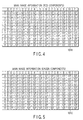
- FIGS. 4 and 5 show an example of the main image information 101.
- FIG. 4 shows the red components 101R of the main image information 101
- FIG. 5 shows the green components 101G thereof. Illustration of the blue components is omitted.
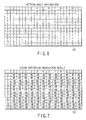
- FIG. 6 shows an example of the pattern image information 102.
- the pattern image information 102 is made of a grid pattern of regular cycles.
- the pattern image information 102 is embedded in the main image information 101 in a state that is not recognizable to the naked eye of a human being.
- the pattern image information 102 contains 1-bit information per pixel (in the range of 0 to 255).
- the pattern image information 102 is assumed to be partly cut out to have a size of 12 ⁇ 12 pixels, as shown in FIG. 6.
- the pattern image information 102 is a grid pattern wherein the unit size is a rectangle of 4 pixels (horizontal) ⁇ 2 pixels (vertical) and which is expressed as a cyclic pattern of black and white rectangles.
- the black color is indicated by "1”
- the white color is indicated by "0.”
- color difference modulation processing step 301 is executed.
- the pattern image information 102 is subjected to color difference modulation processing, using the rules expressed by formulas (a-1) and (a-2) set forth below.
- the color difference modulation processing step 301 creates color difference modulation pattern image information.
- black and white pixels are assigned in accordance with the values of the pixels of the pattern image information 102 in such a manner that a back pixel is assigned to "+1" and a white pixel to "-1.”
- Each of the values is multiplied by a color difference modulation amount ⁇ V.
- This color difference modulation amount ⁇ V is in the range of 0 to 255 and is determined beforehand.
- FIG. 7 shows an example of a result of color difference modulation 102'.
- ⁇ v represents a color difference modulation amount.
- the color difference modulation amount ⁇ V is an integer in the range of 0 to 255 ad is determined beforehand.
- it is desirable that the color difference modulation amount ⁇ V be within the range of 16 to 96. In the present embodiment, ⁇ V 48.
- a superimposition processing step 302 subsequently executed, the color difference modulation pattern image information obtained in the processing described above is synthesized with the main image information 101 prepared beforehand, so as to obtain synthetic image information 103 (103R, 103G, 103b).
- superimposition processing indicated by the formulas (b-1) to (b-3) set forth below is executed.
- DES-R(i,j) SRC-R(i,j) + CDMP(i,j)
- DES-G(i,j) SRC-G(i,j) - CDMP(i,j)
- DES-B(i,j) SRC-B(i,j) - CDMP(i,j)
- SRC-G(i,j) represents the value the main image
- DES-R(i,j), DES-G(i,j) and DES-B(i,j) are integers in the range of 0 to 255. That is, if a result of calculation is less than "0", it is set to be “0”, and if it is greater than "255", it is set to be "255.”
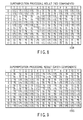
- FIGS. 8 and 9 show results of superimposition processing.
- FIG. 8 indicates the case of red components
- FIG. 9 indicates the case of green components.
- the average of the data values of the 12 ⁇ 12 pixels shown in FIGS. 8 and 9 is "127.”
- the statistic value (average value) of the data values of the main image information is stored.
- the image information subjected to superimposition processing namely, the synthetic image information
- the statistic values of the main image information are preserved. This being so, the synthetic image information and the main image information look like the same from a macroscopic viewpoint, e.g., when they are looked at on the basis of a size of 12 ⁇ 12 pixels.
- the coefficient for the color difference modulation amount ⁇ V alternately takes the values of "+1" and "-1" in accordance with the cycle of the pattern image information 102.
- the signs of the coefficients of the green and blue components are the same, but the signs of the coefficient of the red components differ from them. This is to make use of the complementary-color relationship.
- red and cyan colors are used as complementary. When the sign of the red components is positive (+), the signs of the complementary colors, namely, the green and blue colors, are set to be negative (-). Conversely, when the sign of the red components is negative (-), the signs of the complementary colors, the green and blue colors, are set to be positive (+).
- the value of the pattern image information 102 is set to be that of "black” or “white.”
- the values of the synthetic image information 103 are determined in such a manner that "red” is emphasized.
- the values of the synthetic image information 103 are determined in such a manner that "cyan” is emphasized.
- red-and cyan-color grid components are embedded at positions corresponding to the grid cycles of the pattern image information 102.
- pixels whose data value is 175 emphasize “red”, while pixels whose data value is 79 emphasize “cyan.”
- red color and the cyan colors are complementary, it is hard to make a distinction between red and cyan colors when these colors are adjacent. To the eye of a human being, they look as if they were colorless. In the example shown in FIG. 8, the pixels that are rich in red color and the pixels that are rich in cyan color are repeatedly arranged in a cyclic pattern corresponding to the grid's cyclic pattern of the pattern image information 102.
- the pixels that emphasize the red color i.e., the pixels whose data value is 175) and the pixels that emphasize the cyan color (i.e., the pixels whose data value is 79) are arranged in regular cycles.
- the pixel density is high, the slight differences between the red color and the cyan colors (complementary colors) are hard to perceive to the eye of a human being. To the human eye, the color differences are "0.”
- synthetic image information 103 wherein pattern image information 102 is embedded in main image information 101 in a state that is not recognizable.
- a high-resolution printer e.g., a 300 dpi dye-sublimation type thermal transfer printer
- the synthetic image information 103 looks the same as ordinary image information, and image formats for general-purpose use (such as JPEG and TIFF) can be adopted.
- the synthetic image information 103 can be processed using an application that is adapted to process general types of image information. Accordingly, the system required can be realized with ease. Even if the synthetic image information is converted into another image format, the embedded pattern image information 102 remains the same, and the conversion does not give rise to any problems.
- the synthetic image information 103 is printed or recorded by a high-resolution color printer (e.g., a dye-sublimation type thermal transfer printer), and the resultant information is pasted on an ID card or the like. Therefore, a system that determines whether or not the ID card 105 is authentic, checks the information embedded in the synthetic image information 103 pasted on the ID card 105, and determines whether or not the ID card 105 is authentic on the basis of the check. In other words, the pattern image information 102, which is sub image information invisibly embedded in the verification-use face image of the ID card, is sensed to determine whether or not the ID card 105 is authentic.
- a high-resolution color printer e.g., a dye-sublimation type thermal transfer printer
- the pattern image information 102 which is the sub image information, is sensed by use of the mask sheet 113, and this mask sheet 113 is prepared on the basis of the pattern image information shown in FIG. 6.
- the mask sheet 113 corresponds to the main image information 101 with a 1:1 relationship.
- the pattern image information 102 is made up of black patterns and transparent patterns.
- the black patterns have a value of "1" and do not allow transmission of light, while the transparent patterns have a value of "0" and allow transmission of light.
- the mask sheet 113 is physically laid over the synthetic image 104 printed on the ID card.
- FIG. 10 is a schematic diagram illustrating the synthetic image 104 in the printed state.
- the synthetic image 104 is prepared on the basis of "uniformly-gray" main image information 101, red and cyan cyclic patterns are embedded as grid patterns.
- the pixels indicated by “R” are pixels that are rich in red
- the pixels indicated by “C” are pixels that are rich in cyan.
- FIGS. 11 and 12 schematically show how the synthetic image 104 shown in FIG. 10 will be when it is overlaid with the mask sheet 113 described above.
- FIG. 11 shows the case where the synthetic image 104 and the mask sheet 113 are positioned accurately relative to each other.
- FIG. 12 shows the case where the synthetic image 104 and the mask sheet 113 are shifted from each other by a half period of the cyclic grid pattern.
- the pixels indicated with hatchings are those pixels that are masked by the mask sheet 113.
- the pixels indicated by letter “R” are masked, and the pixels indicated by letter “C” are observable as being transparent. In this state, therefore, the grid looks like a cyan grid partly covered with a black mask.
- the pixels indicated by letter “C” are masked, and the pixels indicated by letter “R” are observable as being transparent. In this state, therefore, the grid looks like a red grid partly covered with a black mask.
- the relative movement between the printed synthetic image 104 and the mask sheet 113 need not be controlled precisely. Instead of the vertical or horizontal movement described above, a rotational movement may be used. In this case, moiré fringes are observed due to the slight shift between the black grid of the mask sheet 113 and the red or cyan grid which is partly covered. The authenticity determination can be made on the basis of the presence of such moiré fringes.
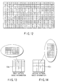
- FIGS. 13 and 14 show two kinds of pattern image information.
- the first pattern image information 102a is similar to the pattern image information 102 of the first embodiment.
- the second pattern image information 102b is prepared by rotating the first pattern image information 102a 90 in the clockwise direction.
- the main image information 101 is divided into N pieces. The manner in which it is divided is optional.
- the main image information 101 is divided into equal pieces, namely, area A (the left half) and area B (the right half).
- the two pieces 102a and 102b of pattern image information are assigned to these two areas A and B.
- the first pattern image information 102a is associated with area A
- the second pattern image information 102b is associated with area B.
- first synthetic image information is prepared by synthesizing the first pattern image information 102a with area A of the main image information 101.
- second synthetic image information is prepared by synthesizing the second pattern image information 102b with area B of the main image information 101.
- FIGS. 17 and 18 An example of the main image information 101 used in the second embodiment is shown in FIGS. 17 and 18.
- FIG. 17 illustrates red components of the main image information 101
- FIG. 18 illustrates green components thereof. Illustration of blue components is omitted.
- the one-dot-chain line indicates the border between these two areas A and B.
- FIGS. 19 and 20 show examples of pattern image information 102a and 202b, respectively.
- FIG. 20 shows examples of pattern image information 102a and 102b.
- the first pattern image information 102a in FIG. 19 uses a pattern similar to that of the pattern image information 102 of the first embodiment, and is partly cut out to have a size of 6 ⁇ 12 pixels.
- the second pattern image information 102b in FIG. 20 is obtained by first rotating the pattern image information 102 of the first embodiment 90° in the clockwise direction and then partly cutting out to have a size of 6 ⁇ 12 pixels.
- the area-A portion of the main image information 101 is synthesized with the first pattern image information 102a in a similar method to that described in connection with the first embodiment.
- the area-B portion of the main image information 101 is synthesized with the second pattern image information 102b in a similar method to that described in connection with the first embodiment.
- the results of these synthetic operations are merely combined together to obtain synthetic image information.
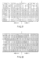
- a schematic diagram illustrating the resultant synthetic image is shown in FIG. 21.
- the pixels indicated by letter "R" are pixels that are rich in red
- the pixels indicated by letter "C" are pixels that are rich in cyan.
- a first mask sheet 113a is prepared beforehand from the first pattern image information 102a.
- the mask sheet 113a is laid on the printed synthetic image 104, as in the first embodiment.
- the states in which the first mask sheet 113 is laid are schematically illustrated in FIGS. 22, 23, 24 and 25.
- FIG. 22 shows the case where the synthetic image 104 and the mask sheet 113a are positioned accurately relative to each other.
- FIG. 23 shows the case where the synthetic image 104 and the mask sheet 113 are shifted from each other by a half period of the cyclic grid pattern.
- the pixels indicated with hatchings are those pixels that are masked by the mask sheet 113a.
- FIG. 24 shows the case where the synthetic image 104 and the 90°-rotated mask sheet 113a are positioned accurately relative to each other.
- FIG. 25 shows the case where the synthetic image 104 and the 90°-rotated mask sheet 113a are shifted from each other by a half period of the cyclic grid pattern.
- the pixels indicated with hatchings are those pixels that are masked by the mask sheet 113a.
- FIG. 26 is a schematic diagram illustrating how verification processing is executed.
- the red and cyan grids alternately appear in area A only. Alternatively, moiré fringes are generated, and changes are thereby produced in the image that is being perceived. On the basis of the presence or absence of such changes, it is possible to determine whether or not the synthetic image 104 is authentic.
- the third embodiment employs first and second pattern image information 102a and 102b that are similar to those described above in connection with the second embodiment.
- an area is divided on the basis of the image information (binary image information) representing the binary values (black and white) of characters or symbols, and the first and second pattern image information 102a and 102b are applied to the divisions of the area.
- the main image information 101 may be a photographic natural image, such as a landscape or a face image for identification.
- the binary image information may be prepared beforehand; alternatively, it may be externally provided when synthetic image information is to be prepared.
- FIG. 27 illustrates an example of a manner in which the first and second pattern image information 102a ad 102b are applied to binary image information 400, which is divided into small areas.
- the first and second pattern image information 102a and 102b are applied to images (410 to 419) of numerals "0" to “9” and images (41A to 41F) of alphabetic characters "A" to "F.”
- the image information serving as the binary image information has the same size as an area to be embedded. For example, when numeral "0" is to be embedded in the entire image information, the binary image information representing numeral "0" is first processed in such a manner that it has the same size as the main image information, and then synthesis processing is executed.
- the binary image information is divided to have desirable dimensions (1 ⁇ m) (Step S1).
- the small areas of the divided binary image information are classified by checking whether they correspond to a character or symbol portion or if they correspond to a background portion, which is other than the character or symbol portion (Step S2).
- Either the first pattern image information 102a or the second pattern image information 102b is assigned to each of the small areas (Step S3).
- the first pattern image information 102a is assigned to the background portion, which is other than the character or symbol
- the second pattern image information 102b is assigned to the character or symbol portion (the non-background portion).
- each small area is subjected to the synthesis processing described in connection with the first embodiment (Step S4).
- synthesis processing By executing synthesis processing for each small area, synthetic image information corresponding to each small area is prepared. All of the resultant synthetic image information corresponding to the respective small areas are merely combined (Step S5).
- the synthetic image information which correspond to the respective small areas, constitute an image having the original size (i.e., the size of the embedding area of the main image information).
- the synthetic image information of the original size is printed on a recording medium by using a high-resolution dye-sublimation type thermal transfer printer, for example (Step S6). In this manner, an ID card bearing the printed synthetic image information is prepared.
- the synthetic image information prepared according to the third embodiment can be checked for authenticity by using the mask sheet 113a based on the first pattern image information 102a in a similar manner to that of the second embodiment.
- a mask sheet 113a is prepared beforehand from the first pattern image information 102a.
- the mask sheet 113a is laid on a synthetic image 104, which is a printed form of the synthetic image information.
- the printed synthetic image 104 and the mask sheet 113a are moved relative to each other, in such a manner that the relative movement is either linear movement (vertical or horizontal movement) or rotation. After this relative movement, the synthetic image 104 has a contrast between the portions where the first pattern image information 102a is embedded and the portions where the second pattern image information 102b is embedded.
- the contrast is produced due to the principle described above in connection with the second embodiment. It should be noted that the portions where the second pattern image information 102b is embedded correspond to the background portions of the characters and symbols of the sub image information and that the portions where the first pattern image information 102a is embedded correspond to the non-background portions (i.e., the characters and symbols themselves). Hence, the characters and background of the sub image information are indicated in the synthetic image, with a contrast being produced.
- an authenticity determination can be made by checking whether the embedded sub image information can be visually perceived.
- characters or symbols can be embedded in a state that cannot be recognized to the eye of a human being, and the characters, symbols or other embedded information can be sensed in a simple and easy method.
- the information processing method described above enables issuance of an ID card bearing a face image which is for identification use and which provides a high degree of security. Since the information used for authenticity determination is embedded in a state that cannot be recognized to the naked eye of a human being, the main image information is allowed to maintain its high quality. Furthermore, an authenticity determination can be easily made with no need to employ a complicated machine.
Landscapes
- Engineering & Computer Science (AREA)
- Physics & Mathematics (AREA)
- General Physics & Mathematics (AREA)
- Theoretical Computer Science (AREA)
- Multimedia (AREA)
- Signal Processing (AREA)
- Image Processing (AREA)
- Editing Of Facsimile Originals (AREA)
- Processing Of Color Television Signals (AREA)
- Facsimile Image Signal Circuits (AREA)
- Credit Cards Or The Like (AREA)
Abstract
Description
Claims (8)
- An information processing method characterized by comprising:a first step (106, 107) of preparing main image information (101) that is recognizable to the naked eye of a human being;a second step (108, 109) of preparing pattern image information (102);a third step (110) of executing color difference modulation processing (301) for the pattern image information (102) prepared in the second step (108, 109) in accordance with a predetermined color difference modulation amount (32), and superimposing the pattern image information (102), which has been modulated in color difference by the color difference modulation processing (301), on the main image information (101) prepared in the first step (106, 107), thereby preparing synthetic image information (103); anda fourth step (111) of recording the synthetic image information (103), prepared in the third step (110), on a recording medium (105) as a visible image.
- An information processing method according to claim 1, characterized in that the pattern image information prepared (102) in the second step (108, 109) has a cyclic grid pattern having a predetermined period.
- An information processing method according to claim 1, characterized in that said third step (110) executes color difference modulation processing (301) such that a first color alternates with a second color complementary thereto, based on the pattern image information (102) prepared in the second step (108, 109), and superimposes the pattern image information (102), which has been modulated in color difference by the color difference modulation processing (301), on the main image information (101) prepared in the first step (106, 107), thereby preparing synthetic image information (103).
- An information processing method characterized by comprising:a first step (106, 107) of preparing main image information (101) that is recognizable to the naked eye of a human being;a second step (108, 109) of preparing a plurality of kinds of pattern image information (102a, 102b), which is defined by a repetition of a pattern image;a third step (110) of preparing synthetic image information (103) by synthesizing the pattern image information (102a, 102b) prepared in the second step (108, 109) with a plurality of areas of the main image information (101) prepared in the first step (106, 107), such that a synthesized state is not recognizable to the naked eye of the human being; anda fourth step (111) of recording the synthetic image information (103), prepared in the third step (110), on a recording medium as a visible image.
- An information processing method according to claim 4, characterized in that said second step (108, 109) prepares a plurality of kinds of pattern image information (102a, 102b), said plurality of kinds of pattern image information (102a, 102b) include first pattern image information (102a) used as a reference, and other pattern image information (102b) obtained by rotating the first pattern image information (102a) by a predetermined angle.
- An image information processing according to claim 4, characterized in that said second step (108, 109) prepares first pattern image information (102a) and second pattern image information (102b), and said second pattern image information (102b) is obtained by rotating the first pattern image information (102a) by 90°.
- An image processing step characterized by comprising:a first step (106, 107) of preparing main image information (101) that is recognizable to the naked eye of a human being;a second step (108, 109) of preparing sub image information (102) by preparing first pattern image information (102a) and second pattern image information (102b) different from the first pattern image information (102a), and by assigning the first and second pattern image information (102a, 102b) to the main image information (101) such that the first pattern image information (102a) is assigned to an area corresponding binary image information representing a character or a symbol and such that the second pattern image information (102b) is assigned to a background area which is other than the area corresponding to the character or the symbol;a third step (110) of preparing synthetic image information (103) by synthesizing the sub image information (102) prepared in the second step (108, 109) with the main image information (101) prepared in the first step (106, 107), such that a synthesized state is not recognizable to the naked eye of the human being; anda fourth step (111) of recording the synthetic image information (103), prepared in the third step (110), on a recording medium (105) as a visible image.
- An image information processing according to claim 7, characterized in that said second step (108, 109) prepares first pattern image information (102a) and second pattern image information (102b), and said second pattern image information (102b) is obtained by rotating the first pattern image information (102a) by a predetermined angle.
Applications Claiming Priority (2)
| Application Number | Priority Date | Filing Date | Title |
|---|---|---|---|
| JP2000078885A JP4495824B2 (en) | 2000-03-21 | 2000-03-21 | Information processing method |
| JP2000078885 | 2000-03-21 |
Publications (3)
| Publication Number | Publication Date |
|---|---|
| EP1136947A2 true EP1136947A2 (en) | 2001-09-26 |
| EP1136947A3 EP1136947A3 (en) | 2003-11-26 |
| EP1136947B1 EP1136947B1 (en) | 2007-02-21 |
Family
ID=18596228
Family Applications (1)
| Application Number | Title | Priority Date | Filing Date |
|---|---|---|---|
| EP01302302A Expired - Lifetime EP1136947B1 (en) | 2000-03-21 | 2001-03-13 | Information processing method |
Country Status (6)
| Country | Link |
|---|---|
| US (1) | US6885755B2 (en) |
| EP (1) | EP1136947B1 (en) |
| JP (1) | JP4495824B2 (en) |
| KR (1) | KR100378911B1 (en) |
| CN (1) | CN1172268C (en) |
| DE (1) | DE60126698T2 (en) |
Cited By (8)
| Publication number | Priority date | Publication date | Assignee | Title |
|---|---|---|---|---|
| EP1385121A1 (en) * | 2002-07-23 | 2004-01-28 | Kabushiki Kaisha Toshiba | Image processing method |
| US6885755B2 (en) | 2000-03-21 | 2005-04-26 | Kabushiki Kaisha Toshiba | Information processing method |
| US6883982B2 (en) | 2003-04-25 | 2005-04-26 | Kabushiki Kaisha Toshiba | Image processing system |
| EP1591953A1 (en) * | 2004-04-26 | 2005-11-02 | Graphic Security Systems Corporation | System and method for decoding digital encoded images |
| EP1671259A4 (en) * | 2003-09-30 | 2008-03-05 | Graphic Security Systems Corp | Method and system for encoding images using encoding parameters from multiple sources |
| EP2028616A1 (en) | 2007-08-17 | 2009-02-25 | Kabushiki Kaisha Toshiba | Image processing method and image processing apparatus |
| US7630513B2 (en) | 2004-04-26 | 2009-12-08 | Graphic Security Systems Corporation | System and method for network-based object authentication |
| US7860268B2 (en) | 2006-12-13 | 2010-12-28 | Graphic Security Systems Corporation | Object authentication using encoded images digitally stored on the object |
Families Citing this family (51)
| Publication number | Priority date | Publication date | Assignee | Title |
|---|---|---|---|---|
| US6763122B1 (en) | 1999-11-05 | 2004-07-13 | Tony Rodriguez | Watermarking an image in color plane separations and detecting such watermarks |
| US6869023B2 (en) | 2002-02-12 | 2005-03-22 | Digimarc Corporation | Linking documents through digital watermarking |
| US7039214B2 (en) | 1999-11-05 | 2006-05-02 | Digimarc Corporation | Embedding watermark components during separate printing stages |
| US6718046B2 (en) | 1995-05-08 | 2004-04-06 | Digimarc Corporation | Low visibility watermark using time decay fluorescence |
| US6763123B2 (en) | 1995-05-08 | 2004-07-13 | Digimarc Corporation | Detection of out-of-phase low visibility watermarks |
| US6721440B2 (en) | 1995-05-08 | 2004-04-13 | Digimarc Corporation | Low visibility watermarks using an out-of-phase color |
| US6590996B1 (en) * | 2000-02-14 | 2003-07-08 | Digimarc Corporation | Color adaptive watermarking |
| US7027614B2 (en) | 2000-04-19 | 2006-04-11 | Digimarc Corporation | Hiding information to reduce or offset perceptible artifacts |
| US6891959B2 (en) | 2000-04-19 | 2005-05-10 | Digimarc Corporation | Hiding information out-of-phase in color channels |
| US7738673B2 (en) | 2000-04-19 | 2010-06-15 | Digimarc Corporation | Low visible digital watermarks |
| US6763124B2 (en) | 2000-04-19 | 2004-07-13 | Digimarc Corporation | Embedding digital watermarks in spot colors |
| US8027509B2 (en) | 2000-04-19 | 2011-09-27 | Digimarc Corporation | Digital watermarking in data representing color channels |
| US6912295B2 (en) | 2000-04-19 | 2005-06-28 | Digimarc Corporation | Enhancing embedding of out-of-phase signals |
| US6804377B2 (en) | 2000-04-19 | 2004-10-12 | Digimarc Corporation | Detecting information hidden out-of-phase in color channels |
| US6993149B2 (en) * | 2001-09-25 | 2006-01-31 | Digimarc Corporation | Embedding digital watermarks in spot colors |
| US7162035B1 (en) | 2000-05-24 | 2007-01-09 | Tracer Detection Technology Corp. | Authentication method and system |
| WO2002039714A2 (en) * | 2000-11-08 | 2002-05-16 | Digimarc Corporation | Content authentication and recovery using digital watermarks |
| US7072487B2 (en) * | 2001-01-26 | 2006-07-04 | Digimarc Corporation | Watermark detection using adaptive color projections |
| US8094869B2 (en) | 2001-07-02 | 2012-01-10 | Digimarc Corporation | Fragile and emerging digital watermarks |
| US7213757B2 (en) | 2001-08-31 | 2007-05-08 | Digimarc Corporation | Emerging security features for identification documents |
| US7537170B2 (en) | 2001-08-31 | 2009-05-26 | Digimarc Corporation | Machine-readable security features for printed objects |
| JP2003174556A (en) * | 2001-09-26 | 2003-06-20 | Canon Inc | Image processing apparatus and image processing method |
| WO2003052680A1 (en) | 2001-12-18 | 2003-06-26 | Digimarc Id System, Llc | Multiple image security features for identification documents and methods of making same |
| US7728048B2 (en) | 2002-12-20 | 2010-06-01 | L-1 Secure Credentialing, Inc. | Increasing thermal conductivity of host polymer used with laser engraving methods and compositions |
| JP3879552B2 (en) * | 2002-03-20 | 2007-02-14 | 富士ゼロックス株式会社 | Image generating apparatus, image reading apparatus, unauthorized duplication prevention system, program, and output medium manufacturing method |
| US7824029B2 (en) | 2002-05-10 | 2010-11-02 | L-1 Secure Credentialing, Inc. | Identification card printer-assembler for over the counter card issuing |
| ATE491190T1 (en) | 2003-04-16 | 2010-12-15 | L 1 Secure Credentialing Inc | THREE-DIMENSIONAL DATA STORAGE |
| WO2005010684A2 (en) * | 2003-07-17 | 2005-02-03 | Digimarc Corporation | Uniquely linking security elements in identification documents |
| US8049933B2 (en) | 2003-09-17 | 2011-11-01 | Canon Kabushiki Kaisha | Copy-forgery-inhibited pattern image generation method and image processing apparatus |
| US20050058476A1 (en) * | 2003-09-17 | 2005-03-17 | Canon Kabushiki Kaisha | Copy-forgery-inhibited pattern density parameter determination method, copy-forgery-inhibited pattern image generation method, and image processing apparatus |
| JP4167590B2 (en) | 2003-12-22 | 2008-10-15 | 株式会社東芝 | Image processing method |
| US7697785B2 (en) * | 2004-03-31 | 2010-04-13 | Fuji Xerox Co., Ltd. | Generating a highly condensed visual summary |
| JP4327676B2 (en) | 2004-07-28 | 2009-09-09 | 株式会社東芝 | Image printing method and image printing apparatus |
| US7848567B2 (en) * | 2004-09-23 | 2010-12-07 | Fuji Xerox Co., Ltd. | Determining regions of interest in synthetic images |
| JP4660212B2 (en) | 2005-01-24 | 2011-03-30 | 株式会社東芝 | Image processing apparatus and image processing method |
| JP4550749B2 (en) | 2006-03-07 | 2010-09-22 | 株式会社東芝 | Image processing method and image processing apparatus |
| EP2009897B1 (en) | 2007-06-27 | 2014-12-24 | Kabushiki Kaisha Toshiba | Image processing apparatus, image processing method, image forming apparatus, image forming method, and recorded material |
| JP2009088614A (en) * | 2007-09-27 | 2009-04-23 | Toshiba Corp | Image processing method and image processing apparatus |
| US7995196B1 (en) | 2008-04-23 | 2011-08-09 | Tracer Detection Technology Corp. | Authentication method and system |
| JP2009290709A (en) * | 2008-05-30 | 2009-12-10 | Canon Inc | Printing system, printing device, image processing apparatus, and control method of the printing system |
| US20090323125A1 (en) * | 2008-06-27 | 2009-12-31 | Kabushiki Kaisha Toshiba | Image generating apparatus |
| JP4686578B2 (en) * | 2008-07-03 | 2011-05-25 | 株式会社東芝 | Image processing method |
| US9117268B2 (en) | 2008-12-17 | 2015-08-25 | Digimarc Corporation | Out of phase digital watermarking in two chrominance directions |
| US8199969B2 (en) | 2008-12-17 | 2012-06-12 | Digimarc Corporation | Out of phase digital watermarking in two chrominance directions |
| JP4913184B2 (en) * | 2009-08-06 | 2012-04-11 | 株式会社東芝 | Identity verification document authenticity determination device, identity verification document authentication method and program |
| AU2011316688B2 (en) | 2010-10-11 | 2014-10-23 | Graphic Security Systems Corporation | Method for constructing a composite image incorporating a hidden authentication image |
| JP5701025B2 (en) * | 2010-11-29 | 2015-04-15 | キヤノン株式会社 | Image processing apparatus, image processing system, control method for image processing apparatus, and program |
| EP3185221B1 (en) | 2015-12-23 | 2023-06-07 | Friedrich Kisters | Authentication apparatus and method for optical or acoustic character recognition |
| KR101879954B1 (en) * | 2016-11-24 | 2018-07-19 | 한국과학기술원 | Method for processing secure image through visual cryptography based on temporal domain and apparatus therefor |
| CN106846271B (en) * | 2017-01-18 | 2020-04-17 | 天津中科智能识别产业技术研究院有限公司 | Method for removing reticulate pattern in identity card photo |
| JP6979694B2 (en) * | 2018-03-22 | 2021-12-15 | 株式会社マーストーケンソリューション | Authentication system, authentication method and authentication program that authenticates hidden images or hidden information |
Family Cites Families (19)
| Publication number | Priority date | Publication date | Assignee | Title |
|---|---|---|---|---|
| JPH0659739A (en) | 1992-08-07 | 1994-03-04 | Sumitomo Heavy Ind Ltd | Double table revolving device |
| US5407893A (en) * | 1993-08-19 | 1995-04-18 | Konica Corporation | Material for making identification cards |
| US6345104B1 (en) | 1994-03-17 | 2002-02-05 | Digimarc Corporation | Digital watermarks and methods for security documents |
| JP3224480B2 (en) * | 1994-09-30 | 2001-10-29 | キヤノン株式会社 | Color image processing equipment |
| US5995638A (en) * | 1995-08-28 | 1999-11-30 | Ecole Polytechnique Federale De Lausanne | Methods and apparatus for authentication of documents by using the intensity profile of moire patterns |
| JP3547892B2 (en) | 1996-03-14 | 2004-07-28 | 株式会社東芝 | Image recording apparatus and image recording method |
| US6095566A (en) * | 1996-03-14 | 2000-08-01 | Kabushiki Kaisha Toshiba | Image recorded product, image recording system, image reproducing system, and recording medium for use to superimpose-record/reproduce additional information |
| US5974150A (en) * | 1997-09-30 | 1999-10-26 | Tracer Detection Technology Corp. | System and method for authentication of goods |
| DE69835133T8 (en) * | 1997-12-03 | 2007-05-16 | Kabushiki Kaisha Toshiba, Kawasaki | Image information processing method and method for preventing counterfeiting of certificates and the like |
| JPH11168616A (en) | 1997-12-03 | 1999-06-22 | Toshiba Corp | Image information processing method and image information processing apparatus |
| JP4015753B2 (en) | 1998-06-11 | 2007-11-28 | 株式会社東芝 | Image information processing method |
| US5946414A (en) * | 1998-08-28 | 1999-08-31 | Xerox Corporation | Encoding data in color images using patterned color modulated image regions |
| US6693647B1 (en) * | 1998-10-19 | 2004-02-17 | Lightsurf Technologies, Inc. | Method and apparatus for displaying notification that a color corrected image is being viewed |
| JP2000182086A (en) | 1998-12-18 | 2000-06-30 | Toshiba Corp | Ticket issuing method and ticket matching method |
| US6556688B1 (en) * | 1999-03-15 | 2003-04-29 | Seiko Epson Corporation | Watermarking with random zero-mean patches for printer tracking |
| JP4495824B2 (en) | 2000-03-21 | 2010-07-07 | 株式会社東芝 | Information processing method |
| JP4038956B2 (en) | 2000-03-23 | 2008-01-30 | 凸版印刷株式会社 | Image generation system and image generation method |
| JP4554771B2 (en) | 2000-06-20 | 2010-09-29 | パナソニック株式会社 | Legitimacy authentication system, personal certificate issuance system and personal certificate |
| JP4828739B2 (en) | 2001-08-17 | 2011-11-30 | 株式会社東芝 | Thermal transfer recording method, printer system, and thermal transfer recording apparatus |
-
2000
- 2000-03-21 JP JP2000078885A patent/JP4495824B2/en not_active Expired - Lifetime
-
2001
- 2001-03-02 KR KR10-2001-0010746A patent/KR100378911B1/en not_active Expired - Lifetime
- 2001-03-09 CN CNB011178663A patent/CN1172268C/en not_active Expired - Fee Related
- 2001-03-13 EP EP01302302A patent/EP1136947B1/en not_active Expired - Lifetime
- 2001-03-13 DE DE60126698T patent/DE60126698T2/en not_active Expired - Lifetime
- 2001-03-21 US US09/812,887 patent/US6885755B2/en not_active Expired - Lifetime
Cited By (15)
| Publication number | Priority date | Publication date | Assignee | Title |
|---|---|---|---|---|
| US6885755B2 (en) | 2000-03-21 | 2005-04-26 | Kabushiki Kaisha Toshiba | Information processing method |
| EP1385121A1 (en) * | 2002-07-23 | 2004-01-28 | Kabushiki Kaisha Toshiba | Image processing method |
| US6901862B2 (en) | 2002-07-23 | 2005-06-07 | Kabushiki Kaisha Toshiba | Image processing method |
| US7489800B2 (en) | 2002-07-23 | 2009-02-10 | Kabushiki Kaisha Toshiba | Image processing method |
| US6883982B2 (en) | 2003-04-25 | 2005-04-26 | Kabushiki Kaisha Toshiba | Image processing system |
| US7386177B2 (en) | 2003-09-30 | 2008-06-10 | Graphic Security Systems Corp. | Method and system for encoding images using encoding parameters from multiple sources |
| EP1671259A4 (en) * | 2003-09-30 | 2008-03-05 | Graphic Security Systems Corp | Method and system for encoding images using encoding parameters from multiple sources |
| EP1591953A1 (en) * | 2004-04-26 | 2005-11-02 | Graphic Security Systems Corporation | System and method for decoding digital encoded images |
| US7512249B2 (en) | 2004-04-26 | 2009-03-31 | Graphic Security Systems Corporation | System and method for decoding digital encoded images |
| US7561308B2 (en) | 2004-04-26 | 2009-07-14 | Graphic Security Systems Corporation | System and method for decoding digital encoded images |
| US7630513B2 (en) | 2004-04-26 | 2009-12-08 | Graphic Security Systems Corporation | System and method for network-based object authentication |
| US7860268B2 (en) | 2006-12-13 | 2010-12-28 | Graphic Security Systems Corporation | Object authentication using encoded images digitally stored on the object |
| EP2028616A1 (en) | 2007-08-17 | 2009-02-25 | Kabushiki Kaisha Toshiba | Image processing method and image processing apparatus |
| EP2146313A1 (en) * | 2007-08-17 | 2010-01-20 | Kabushi Kaisha Toshiba | Image processing method and image processing apparatus |
| US8175323B2 (en) | 2007-08-17 | 2012-05-08 | Kabushiki Kaisha Toshiba | Image processing method and image processing apparatus |
Also Published As
| Publication number | Publication date |
|---|---|
| JP4495824B2 (en) | 2010-07-07 |
| EP1136947B1 (en) | 2007-02-21 |
| CN1324058A (en) | 2001-11-28 |
| KR20010089182A (en) | 2001-09-29 |
| EP1136947A3 (en) | 2003-11-26 |
| KR100378911B1 (en) | 2003-04-07 |
| JP2001268346A (en) | 2001-09-28 |
| US20010040980A1 (en) | 2001-11-15 |
| CN1172268C (en) | 2004-10-20 |
| US6885755B2 (en) | 2005-04-26 |
| DE60126698D1 (en) | 2007-04-05 |
| DE60126698T2 (en) | 2007-10-25 |
Similar Documents
| Publication | Publication Date | Title |
|---|---|---|
| EP1136947B1 (en) | Information processing method | |
| US6438251B1 (en) | Method of processing image information and method of preventing forgery of certificates or the like | |
| AU748031C (en) | Anti-counterfeiting method and apparatus using digital screening | |
| US8985634B2 (en) | Anti-counterfeit printed matter, method of manufacturing the same, and recording medium storing halftone dot data creation software | |
| US6600571B1 (en) | Method, apparatus and recording medium for image printing | |
| US7489800B2 (en) | Image processing method | |
| US20010022667A1 (en) | Method, apparatus, and recording medium for outputting images | |
| US6414757B1 (en) | Document security system and method | |
| JPH11168616A (en) | Image information processing method and image information processing apparatus | |
| JP2001094755A (en) | Image processing method | |
| JPH03193495A (en) | ID card counterfeit prevention processing method and counterfeit prevention ID card | |
| JPH09277761A (en) | Personal identification medium and manufacturing method thereof | |
| KR20010034101A (en) | Anti-counterfeiting method and apparatus using digital screening | |
| HK1055344A (en) | Anti-counterfeiting decoding method and apparatus |
Legal Events
| Date | Code | Title | Description |
|---|---|---|---|
| PUAI | Public reference made under article 153(3) epc to a published international application that has entered the european phase |
Free format text: ORIGINAL CODE: 0009012 |
|
| 17P | Request for examination filed |
Effective date: 20010409 |
|
| AK | Designated contracting states |
Kind code of ref document: A2 Designated state(s): AT BE CH CY DE DK ES FI FR GB GR IE IT LI LU MC NL PT SE TR |
|
| AX | Request for extension of the european patent |
Free format text: AL;LT;LV;MK;RO;SI |
|
| PUAL | Search report despatched |
Free format text: ORIGINAL CODE: 0009013 |
|
| AK | Designated contracting states |
Kind code of ref document: A3 Designated state(s): AT BE CH CY DE DK ES FI FR GB GR IE IT LI LU MC NL PT SE TR |
|
| AX | Request for extension of the european patent |
Extension state: AL LT LV MK RO SI |
|
| 17Q | First examination report despatched |
Effective date: 20040607 |
|
| AKX | Designation fees paid |
Designated state(s): DE FR GB |
|
| GRAP | Despatch of communication of intention to grant a patent |
Free format text: ORIGINAL CODE: EPIDOSNIGR1 |
|
| GRAS | Grant fee paid |
Free format text: ORIGINAL CODE: EPIDOSNIGR3 |
|
| GRAA | (expected) grant |
Free format text: ORIGINAL CODE: 0009210 |
|
| AK | Designated contracting states |
Kind code of ref document: B1 Designated state(s): DE FR GB |
|
| REG | Reference to a national code |
Ref country code: GB Ref legal event code: FG4D |
|
| PGFP | Annual fee paid to national office [announced via postgrant information from national office to epo] |
Ref country code: GB Payment date: 20070307 Year of fee payment: 7 |
|
| REF | Corresponds to: |
Ref document number: 60126698 Country of ref document: DE Date of ref document: 20070405 Kind code of ref document: P |
|
| ET | Fr: translation filed | ||
| PLBE | No opposition filed within time limit |
Free format text: ORIGINAL CODE: 0009261 |
|
| STAA | Information on the status of an ep patent application or granted ep patent |
Free format text: STATUS: NO OPPOSITION FILED WITHIN TIME LIMIT |
|
| 26N | No opposition filed |
Effective date: 20071122 |
|
| GBPC | Gb: european patent ceased through non-payment of renewal fee |
Effective date: 20080313 |
|
| PG25 | Lapsed in a contracting state [announced via postgrant information from national office to epo] |
Ref country code: GB Free format text: LAPSE BECAUSE OF NON-PAYMENT OF DUE FEES Effective date: 20080313 |
|
| REG | Reference to a national code |
Ref country code: FR Ref legal event code: PLFP Year of fee payment: 16 |
|
| REG | Reference to a national code |
Ref country code: FR Ref legal event code: PLFP Year of fee payment: 17 |
|
| REG | Reference to a national code |
Ref country code: FR Ref legal event code: PLFP Year of fee payment: 18 |
|
| PGFP | Annual fee paid to national office [announced via postgrant information from national office to epo] |
Ref country code: DE Payment date: 20200303 Year of fee payment: 20 |
|
| PGFP | Annual fee paid to national office [announced via postgrant information from national office to epo] |
Ref country code: FR Payment date: 20200214 Year of fee payment: 20 |
|
| REG | Reference to a national code |
Ref country code: DE Ref legal event code: R071 Ref document number: 60126698 Country of ref document: DE |