EP1136939A2 - Capacitance change-based input device and detection device - Google Patents
Capacitance change-based input device and detection device Download PDFInfo
- Publication number
- EP1136939A2 EP1136939A2 EP01301994A EP01301994A EP1136939A2 EP 1136939 A2 EP1136939 A2 EP 1136939A2 EP 01301994 A EP01301994 A EP 01301994A EP 01301994 A EP01301994 A EP 01301994A EP 1136939 A2 EP1136939 A2 EP 1136939A2
- Authority
- EP
- European Patent Office
- Prior art keywords
- elastic body
- input
- electrodes
- electrode
- slider
- Prior art date
- Legal status (The legal status is an assumption and is not a legal conclusion. Google has not performed a legal analysis and makes no representation as to the accuracy of the status listed.)
- Withdrawn
Links
Images





Classifications
-
- G—PHYSICS
- G06—COMPUTING OR CALCULATING; COUNTING
- G06F—ELECTRIC DIGITAL DATA PROCESSING
- G06F3/00—Input arrangements for transferring data to be processed into a form capable of being handled by the computer; Output arrangements for transferring data from processing unit to output unit, e.g. interface arrangements
- G06F3/01—Input arrangements or combined input and output arrangements for interaction between user and computer
- G06F3/03—Arrangements for converting the position or the displacement of a member into a coded form
- G06F3/033—Pointing devices displaced or positioned by the user, e.g. mice, trackballs, pens or joysticks; Accessories therefor
- G06F3/0354—Pointing devices displaced or positioned by the user, e.g. mice, trackballs, pens or joysticks; Accessories therefor with detection of two-dimensional [2D] relative movements between the device, or an operating part thereof, and a plane or surface, e.g. 2D mice, trackballs, pens or pucks
- G06F3/03548—Sliders, in which the moving part moves in a plane
-
- H—ELECTRICITY
- H01—ELECTRIC ELEMENTS
- H01H—ELECTRIC SWITCHES; RELAYS; SELECTORS; EMERGENCY PROTECTIVE DEVICES
- H01H13/00—Switches having rectilinearly-movable operating part or parts adapted for pushing or pulling in one direction only, e.g. push-button switch
- H01H13/02—Details
- H01H13/26—Snap-action arrangements depending upon deformation of elastic members
-
- G—PHYSICS
- G06—COMPUTING OR CALCULATING; COUNTING
- G06F—ELECTRIC DIGITAL DATA PROCESSING
- G06F3/00—Input arrangements for transferring data to be processed into a form capable of being handled by the computer; Output arrangements for transferring data from processing unit to output unit, e.g. interface arrangements
- G06F3/01—Input arrangements or combined input and output arrangements for interaction between user and computer
- G06F3/03—Arrangements for converting the position or the displacement of a member into a coded form
- G06F3/033—Pointing devices displaced or positioned by the user, e.g. mice, trackballs, pens or joysticks; Accessories therefor
- G06F3/0338—Pointing devices displaced or positioned by the user, e.g. mice, trackballs, pens or joysticks; Accessories therefor with detection of limited linear or angular displacement of an operating part of the device from a neutral position, e.g. isotonic or isometric joysticks
Definitions
- the present invention relates to an input device for use in personal computers and remote controllers and to a detection device for use in accelerometers and, particularly, to a capacitance change-based input device and detection device.
- a capacitance change-based input device and detection device each comprising:
- a capacitance change-based input device and detection device each of which has a tension application means such as an annular projection, or cutout portion or inclined portion to apply tension to the elastic body.
- a capacitance change-based input device and detection device wherein a connection portion between the elastic body and the slider is covered with the key top.
- a capacitance change-based input device and detection device each comprising:
- a capacitance change-based input device and detection device each of which has a tension application means such as an annular projection, or cutout portion or inclined portion is provided to apply tension to the elastic body.
- a capacitance change-based input device and detection device wherein a connection portion between the elastic body and the slider is covered with the key top.
- the input device is essentially comprised of a key top 1, slider 2, housing 3 made of a metal plate, bracket 4 made of a metal plate, pressing body 5, elastic body 6, a support member 7 made of a synthetic resin molded product and printed wiring board 8.
- the key top 1 is molded to a shape shown in Fig. 1 from an elastic material such as rubber or elastomer and an input operation surface 9 which is greatly depressed in a circular arc is formed on the center portion of the top surface.
- a projection portion 10 which is thinner than the peripheral portion and can move vertically is provided on the center portion in such a manner that it faces down and a lower end side wall 11 is mated with the slider 2.
- the slider 2 is molded from a hard synthetic resin, a hole 12 which mates with the head portion of the elastic body 6 is formed in the center portion, and a connection portion between this slider 2 and the elastic body 6 is covered with the key top 1 mounted to the top of the slider 2.
- a flange portion 13 provided at the periphery of the slider 2 is sandwiched between the bracket 4 and the upper end bent portion 8 of the housing 3 in such a manner that it can slide. Therefore, the slider 2 is arranged such that it can move in a horizontal direction (X and Y directions), the key top 1 can move in a horizontal direction (X and Y directions) together with the slider 2, and the center portion (projection portion 10) can move in a vertical direction (Z direction).
- the elastic body 6 comprised of an elastic main body 6a which is relatively thick and has no conductivity and a conductive elastic body 6b arranged under the elastic main body 6a.
- the both members are integrated with each other by such means as two-color molding or adhesion.
- a storage depressed portion 15 having a larger inner diameter than the outer diameter of the pressing body 5 is formed in the center portion of the elastic main body 6a and a thin portion 16 is formed at the bottom of the storage depressed portion 15 to store the pressing body 5 in the storage depressed portion 15 such that it can move vertically.
- the pressing body 5 is made from a hard material such as a hard synthetic resin or metal and columnar in shape.
- the conductive elastic body 6b is made from an elastic material such as rubber or elastomer containing conductive fine particles such as silver or carbon black dispersed therein, and an annular projection 17 larger in diameter than the thin portion 16 projects downward and slightly more than the peripheral portion 18 of the conductive elastic body 6b.
- the peripheral portion 18 of the ela-stic body 6 (conductive elastic body 6b) is fixed and positioned to the printed wiring board 8 by adhesion or the like, the annular projection 17 of the conductive elastic body 6b is press contacted to the top surface of the printed wiring board 8, and a space 19 is maintained between the conductive elastic body 6b and the printed wiring board 8 while tension is applied to the conductive elastic body 6b.
- a first electrode 20a is formed at the center
- a second electrode 20b, third electrode 20c, fourth electrode 20d and fifth electrode 20e are formed around the first electrode 20a
- a gland electrode 20f is provided around the above electrodes
- all the above electrodes 20 are covered with a soft insulating film 21 for maintaining a space therebetween as shown in Fig. 6, and the areas of the second to fifth electrodes 20b to 20e are equal to one another.
- the electrodes 20 and the insulating film 21 are omitted to simplify the illustration.
- the second electrode 20b is for moving a cursor on a display in an upward direction
- the third electrode 20c for moving the cursor in a downward direction
- the fourth electrode 20d for moving the cursor in a left direction
- the fifth electrode 20e for moving the cursor in a right direction.
- the second to fifth electrodes 20b to 20e are for inputting data in a horizontal direction (X and Y directions).
- the first electrode 20a is used to confirm the input direction and to input data in a vertical direction (Z direction).
- a conductive pattern 22 having a predetermined shape is provided on the under surface of the printed wiring board 8 and the above electrodes 20 are electrically connected to the conductive pattern 22 by through holes 23.
- An electronic part such as an IC chip 24 is mounted on the conductive pattern 22, a flexible printed wiring board 25 is connected to one end of the conductive pattern 22, and the other end of the flexible printed wiring board 25 is connected to the input/output interface (not shown) of an apparatus in use.
- the peripheral portion (slider 2) of the key top 1 is prevented from moving in a vertical direction (Z direction) and allowed to move only in a horizontal direction (X and Y directions).
- Fig. 7 is a sectional view of the elastic body 6 used in a second embodiment.
- the difference of the elastic body 6 from the elastic body 6 of a first embodiment is that the thin portion 16 is not provided on the elastic main body 6a, a hole is formed in the elastic main body 6a, and an opening at the lower end of the hole is covered by the center portion of the conductive elastic body 6b to form the storage depressed portion 15.
- Fig. 8 is a sectional view of the elastic body 6 used in a third embodiment.
- the whole elastic body 6 is comprised of the conductive elastic body 6b and the storage depressed portion 15 and the thin portion 16 are formed at the center portion.
- the annular projection 17 is not provided on the elastic body 6 and an annular projection 26 slightly larger in diameter than the thin portion 16 is formed on the printed wiring board 8.
- the annular projection 26 is designed to be slightly larger in height than the inner level difference of the peripheral portion 18 of the conductive elastic body 6b and press contacted to the under surface of the conductive elastic body 6b when the device is assembled to apply appropriate tension to the conductive elastic body 6b.
- annular projection 26 on the printed wiring board 8 is applicable to the first and second embodiments.
- Fig. 9 is a sectional view of key parts of an input device according to a fourth embodiment.
- An inclined or round cutout portion 27 is formed at the periphery of the under surface of the elastic body 6.
- the cutout portion 27 is smashed by pressing force at the time of assembly (Fig. 9 does not illustrate the smashed cutout portion 27), whereby tension (stress) is generated in the elastic body 6.
- Fig. 10 is a sectional view of key parts of an input device according to a fifth embodiment.
- a wide-angle inclined portion 28 whose diameter increases toward the upper end is formed on the end portion of the top surface of the elastic body 6, and a V-shaped bent pressing portion 40 is provided on a pressing member such as the bracket 4 to press the inclined portion 28 outward in a radial direction.
- the inclined portion 28 is pressed outward in a radial direction by the pressure of this pressing portion 40 to generate tension (stress) in the elastic body 6.
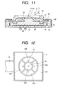
- Fig. 11 is a sectional view of an input device
- Fig. 12 is a plan view of a printed wiring board
- Fig. 13 is a sectional view of the printed wiring board.
- the input device is essentially comprised of a slider 69 which also serves as a key top, key top 51, housing 52 made of a metal plate, a support member 53 made of a synthetic resin molded product, elastic body 54 and printed wiring board 55.
- the slider 69 is molded to a shape shown in Fig. 11 from a hard synthetic resin, a hole 56 which mates with the head portion 59 of the key top 51 is formed in the center portion, and a flange portion 57 at the periphery is mounted on the support member 53 such that it can move in a horizontal direction (X and Y directions) between the upper end bent portion 58 of the housing 52 and the support member 53.
- the key top 51 is molded to a shape shown in Fig. 11 from an elastic material such as rubber or elastomer, and the head portion 59 is exposed to the outside from the hole 56 and mated with the elastic body 54.
- the key top 51 can move in a horizontal direction (X and Y directions) together with the slider 69 and can move alone in a vertical direction (Z direction).
- the elastic body 54 comprised of an elastic main body 54a which is relatively thick and has no conductivity and a conductive elastic body 54b which is arranged under the elastic main body 54a.
- the both members are integrated with each other by such means as two-color molding or adhesion.
- the conductive elastic body 54b is made from an elastic material such as rubber or elastomer containing conductive fine particles such as silver or carbon dispersed therein.
- the peripheral portion 60 of the elastic body 54 is fixed or positioned to a printed wiring board 55 by adhesion or the like, a projection 61 for applying tension which is contacted to the printed wiring board 55 is provided at the center of the under surface of the conductive elastic body 54b, and a space 62 is formed between the conductive elastic body 54b and the printed wiring board 55 by the peripheral portion 60 and the projection 61.
- a first electrode 63a is formed at the center
- second electrode 63b third electrode 63c, fourth electrode 63d and fifth electrode 63e are formed around the first electrode 63a
- a gland electrode 63f is provided around the above electrodes, and the above electrodes 63 are covered with a soft insulating film 64 for maintaining a space therebetween as shown in Fig, 13, and the areas of the second to fifth electrodes 63b to 63e are equal to one another.
- the second electrode 63b is for moving the cursor on the display in an upward direction
- the third electrode 63c for moving it in a downward direction
- the fourth electrode 63d for moving it in a left direction
- the fifth electrode 63e for moving it in a right direction.
- the second to fifth electrodes 63b to 63e are for inputting data in a horizontal direction (X and Y directions).
- the first electrode 63a is used to confirm the input direction and to input data in a vertical direction (Z direction).
- a conductive pattern 65 having a predetermined shape is provided on the under surface of the printed wiring board 55 and the above electrodes 63 are electrically connected to the conductive pattern 65 by through holes 66.
- An electronic part such as an IC chip 67 is mounted on the conductive pattern 65, a flexible printed wiring board 68 is connected to one end of the conductive pattern 65, and the other end of the flexible printed wiring board 68 is connected to the input/output interface (not shown) of an apparatus in use.
- the slider 69 Since the flange portion 57 of the slider 69 is sandwiched between the support member 53 and the upper end bent portion 58 of the housing 52 when the slider 69 is operated, the slider 69 is prevented from moving in a vertical direction (Z direction) and allowed to move only in a horizontal direction (X and Y directions).
- the slider 69 When the key top 51 is pressed in a vertical direction (Z direction) by the finger in Fig. 11, the slider 69 is kept at that position and only the key top 51 is moved down. The space between the first electrode 63a and the conductive elastic body 54b is narrowed from the initial state, a change in capacitance is electrically detected, and a signal is input by the key top 51. When operation force applied to the key top 51 and the slider 69 is removed, the key top 51, slider 69 and elastic body 54 are returned to the original stand-by mode by the restoring force of the elastic body 54.
- Figs. 14 to 16 are for explaining an input device according to a seventh embodiment.
- Fig. 14 is a sectional view of the input device
- Fig. 15 is a perspective view of the input device
- Fig. 16 is an exploded perspective view of the input device.
- the input device is essentially comprised of a key top 51, housing 52, a support member 53, elastic body 54, printed wiring board 55, slider 69 and bracket 70.
- the key top 51 is molded to a shape shown in Fig. 14 from an elastic material such as rubber or elastomer and an input operation surface 71 which is greatly depressed in a circular arc is formed on the center portion of the top surface.
- a projection portion 72 which is thinner than the peripheral portion and can move vertically is provided on the center portion in such a manner that it faces down and a lower end side wall 73 is mated with the slider 69.
- the slider 69 is molded from a hard synthetic resin, a hole 74 which mates with the head portion of the elastic body 54 is formed in the center portion, and a connection portion between this slider 69 and the elastic body 54 is covered with the key top 51 mounted to the top of the slider 69.
- a flange portion 57 provided at the periphery of the slider 69 is sandwiched between the bracket 70 and the upper end bent portion 58 of the housing 52 in such a manner that it can slide.
- the whole elastic body 54 has conductivity and its head portion exposes from the hole 74 of the slider 69 and contacts or approaches the projection portion 72 of the key top 51 so that the elastic body 54 is fixed to a predetermined position of the printed wiring board 55.
- first to fifth electrodes 63a to 63e and a gland electrode 63f are provided on the printed wiring board 55 and the first to fifth electrodes 63a to 63e face the under surface of the elastic body 54 with a space 62 therebetween.
- the peripheral portion (slider 69) of the key top 51 is prevented from moving in a vertical direction (Z direction) and allowed to move only in a horizontal direction (X and Y directions) because the flange portion 57 of the slider 69 which mates with the key top 51 is sandwiched between the bracket 70 and the upper end bent portion 58 of the housing 52.
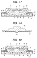
- Fig. 17 and Fig. 18 are for explaining an input device according to an eighth embodiment.
- Fig. 17 is a sectional view of the input device and
- Fig. 18 is a sectional view of an elastic body before it is set in the input device.
- the difference between the eighth embodiment and the seventh embodiment is the shape of the elastic body.
- a projection portion 61 is provided on the center portion of the under surface of the elastic body 54 and projects down slightly more than the peripheral portion 60.
- the elastic body 54 is elastically deformed by operation force, as distortion remains in the elastic body 54, when operation force is very small, it may be offset with the residual distortion and an appropriate signal may not be input.
- tension (stress) is applied to the elastic body 54 as in this embodiment, even if operation force is very small, an appropriate signal can be input.
- the projection portion 61 provided on the conductive elastic body 54b shown in Fig. 11 takes part in the application of tension (stress) to the conductive elastic body 54b.
- Fig. 19 is for explaining an input device according to a ninth embodiment.
- an inclined or round cutout portion 76 is provided at the periphery of the under surface of the elastic body 54.
- the cutout portion 76 is smashed by pressure at the time of assembly (Fig. 19 does not illustrate the smashed cutout portion 76), thereby generating tension (stress) F in the elastic body 54. Since tension (stress) F is generated in the elastic body 54 by the cutout portion 76, the thickness of the peripheral portion of the elastic body 54 is designed to be larger than the thickness of the support member 53 by the smashed portion of the cutout portion 76.
- Fig. 20 and Fig. 21 show a first application example of the input device in a mobile personal computer or a notebook personal computer.
- the personal computer 80 comprises a personal computer body 82 having a large number of key board switches 81 and a cover member 84 having a display portion 83, and the cover member 84 is attached to the personal computer body 82 such that it can move.
- the above, input device 85 is incorporated in the end portion of the cover member 84 as an input pointer.
- the input device 85 is incorporated in the cover member 84 but can be incorporated in the personal computer body 82.
- Fig. 21 shows the operation state of the input device 85.
- a cursor on the display portion 83 can be moved by sandwiching the input device 85 between the thumb 86 and another finger 87 and moving the thumb 86 vertically and horizontally.
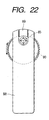
- Fig. 22 shows a second application example of the input device in a remote controller for a mobile personal computer or notebook personal computer for domestic use.
- the above input device 85 as an input pointer, switch 89 and scroll dial 90 are incorporated in a remote control body 88. While the remote controller for a personal computer has been described in this example, the present invention can be applied to a remote controller for other apparatus.
- the input device is used in a personal computer in the above examples, it may be used in such fields as electric appliances, car equipment, measuring instruments and medical appliances.
- the number of separate electrodes may be smaller than that in the above embodiments.
- the present invention is not limited to this and is applicable to a detection device for detecting deformation as a change in capacitance by installing a detector on a portion corresponding to the key top or slider of the input device in such a manner it can move (slide or rotate), moving the detector by action force (force, magnetic force or wind force) from an object to be detected, and deforming an elastic body by this movement.
- the present invention is constituted as described above, comprises a slider movable only in a horizontal direction, a key top movable in a vertical direction and a pressing body and clearly distinguishes input in a horizontal direction from input in a vertical direction, and the pressing body is hard, it can provide an input device and a detection device which have high input accuracy (detection accuracy) and excellent handling ease.
- the present invention has a tension application means of applying tension to the elastic body, input can be made with small force and input accuracy (detection accuracy) can be further improved.
- connection portion between the elastic body and the slider is covered with the top key in the present invention, dust does not adhere to or enter the connection portion, thereby making it possible to improve operation reliability.
Landscapes
- Engineering & Computer Science (AREA)
- General Engineering & Computer Science (AREA)
- Theoretical Computer Science (AREA)
- Human Computer Interaction (AREA)
- Physics & Mathematics (AREA)
- General Physics & Mathematics (AREA)
- Switches With Compound Operations (AREA)
- Push-Button Switches (AREA)
- Input From Keyboards Or The Like (AREA)
Abstract
Description
Claims (12)
- An input device comprising:separate electrodes comprised of an electrode for detecting input in a vertical direction and a plurality of electrodes for detecting input in a horizontal direction and arranged separately on the surface;an elastic body which faces the above separate electrodes with a predetermined space therebetween, at least a portion opposite to the separate electrodes having conductivity, a thin portion being provided opposite to the electrode for detecting input in a vertical direction, a storage depressed portion being formed on the thin portion, and the space between the elastic body and the separate electrodes changing by input;a slider connected to the elastic body and movable only in a horizontal direction;a hard pressing body stored in the storage depressed portion of the elastic body; anda key top whose portion opposite to the pressing body is movable in a vertical direction, whereinwhen the slider is moved in a horizontal direction, the elastic body deforms and the space between the conductive portion of the elastic body and the electrodes for detecting input in a horizontal direction changes, and when the key top is pressed, the thin portion of the elastic body deforms through the pressing body and the space between the thin portion and the electrode for detecting input in a vertical direction changes.
- The input device of claim 1 which has tension application means of applying tension to the elastic body.
- The input device of claim 1 or 2, wherein a connection portion between the elastic body and the slider is covered with the key top.
- A detection device comprising:separate electrodes comprised of an electrode for detecting input in a vertical direction and a plurality of electrodes for detecting input in a horizontal direction and arranged separately on the surface;an elastic body which faces the above separate electrodes with a predetermined space therebetween, at least a portion opposite to the separate electrodes having conductivity, a thin portion being provided opposite to the electrode for detecting input in a vertical direction, a storage depressed portion being formed on the thin portion, and the space between the elastic body and the separate electrodes changing by input;a slider connected to the elastic body and movable only in a horizontal direction;a hard pressing body stored in the storage depressed portion of the elastic body; anda key top whose portion opposite to the pressing body is movable in a vertical direction, whereinwhen the slider is moved in a horizontal direction, the elastic body deforms and the space between the conductive portion of the elastic body and the electrodes for detecting input in a horizontal direction changes, and when the key top is pressed, the thin portion of the elastic body deforms through the pressing body and the space between the thin portion and the electrode for detecting input in a vertical direction changes.
- The detection device of claim 4 which has a tension application means of applying tension to the elastic body.
- The detection device of claim 4 or 5, wherein a connection portion between the elastic body and the slider is covered with the key top.
- An input device comprising:separate electrodes comprised of an electrode for detecting input in a vertical direction and a plurality of electrodes for detecting input in a horizontal direction and arranged separately on the surface;an elastic body which faces the above separate electrodes with a predetermined space therebetween, at least a portion opposite to the separate electrodes having conductivity, and the space between the elastic body and the electrodes changing by input;a slider connected to the elastic body and movable only in a horizontal direction; anda key top whose portion opposite to the electrode for detecting input in a vertical direction is movable at least in a vertical direction through the elastic body, whereinwhen the slider is moved in a horizontal direction, the elastic body deforms and the space between the conductive portion of the elastic body and the electrodes for detecting input in a horizontal direction changes, and when the key top is pressed, the elastic body deforms and the space between the conductive portion of the elastic body and the electrode for detecting in a vertical direction changes.
- The input device of claim 7 which has a tension application means of applying tension to the elastic body.
- The input device of claim 7 or 8, wherein a connection portion between the elastic body and the slider is covered with the key top.
- A detection device comprising:separate electrodes comprised of an electrode for detecting input in a vertical direction and a plurality of electrodes for detecting input in a horizontal direction and arranged separately on the surface;an elastic body which faces the above separate electrodes with a predetermined space therebetween, at least a portion opposite to the separate electrodes having conductivity, and the space between the elastic body and the electrodes changing by input;a slider connected to the elastic body and movable only in a horizontal direction; anda key top whose portion opposite to the electrode for detecting input in a vertical direction is movable at least in a vertical direction through the elastic body, whereinwhen the slider is moved in a horizontal direction, the elastic body deforms and the space between the conductive portion of the elastic body and the electrodes for detecting input in a horizontal direction changes, and when the key top is pressed, the elastic body deforms and the space between the conductive portion of the elastic body and the electrode for detecting in a vertical direction changes.
- The detection device of claim 10 which has a tension application means of applying tension to the elastic body.
- The detection device of claim 10 or 11, wherein a connection portion between the elastic body and the slider is covered with the key top.
Applications Claiming Priority (4)
| Application Number | Priority Date | Filing Date | Title |
|---|---|---|---|
| JP2000070888A JP3954270B2 (en) | 2000-03-14 | 2000-03-14 | Input device and detection device |
| JP2000070886 | 2000-03-14 | ||
| JP2000070888 | 2000-03-14 | ||
| JP2000070886A JP3971079B2 (en) | 2000-03-14 | 2000-03-14 | Input device and detection device |
Publications (2)
| Publication Number | Publication Date |
|---|---|
| EP1136939A2 true EP1136939A2 (en) | 2001-09-26 |
| EP1136939A3 EP1136939A3 (en) | 2004-04-14 |
Family
ID=26587464
Family Applications (1)
| Application Number | Title | Priority Date | Filing Date |
|---|---|---|---|
| EP01301994A Withdrawn EP1136939A3 (en) | 2000-03-14 | 2001-03-05 | Capacitance change-based input device and detection device |
Country Status (4)
| Country | Link |
|---|---|
| US (1) | US6508137B2 (en) |
| EP (1) | EP1136939A3 (en) |
| KR (1) | KR100381939B1 (en) |
| CN (1) | CN1319790A (en) |
Cited By (6)
| Publication number | Priority date | Publication date | Assignee | Title |
|---|---|---|---|---|
| WO2005055039A3 (en) * | 2003-11-24 | 2005-09-15 | Agilent Technologies Inc | A modular assembly for a self-indexing computer pointing device |
| US7586480B2 (en) | 2005-02-28 | 2009-09-08 | Avago Technologies Ecbu Ip (Singapore) Pte. Ltd. | Hybrid pointing device |
| US7701440B2 (en) | 2005-12-19 | 2010-04-20 | Avago Technologies Ecbu Ip (Singapore) Pte. Ltd. | Pointing device adapted for small handheld devices having two display modes |
| US7889176B2 (en) | 2006-07-18 | 2011-02-15 | Avago Technologies General Ip (Singapore) Pte. Ltd. | Capacitive sensing in displacement type pointing devices |
| US7978175B2 (en) | 2007-11-23 | 2011-07-12 | Avago Technologies Ecbu Ip (Singapore) Pte. Ltd. | Magnetic re-centering mechanism for a capacitive input device |
| US8232963B2 (en) | 2007-08-27 | 2012-07-31 | Avago Technologies Ecbu Ip (Singapore) Pte. Ltd. | Control and data entry apparatus |
Families Citing this family (23)
| Publication number | Priority date | Publication date | Assignee | Title |
|---|---|---|---|---|
| US6756703B2 (en) * | 2002-02-27 | 2004-06-29 | Chi Che Chang | Trigger switch module |
| JP2003329444A (en) * | 2002-03-07 | 2003-11-19 | Alps Electric Co Ltd | Capacitance type sensor |
| US20040040800A1 (en) * | 2002-07-31 | 2004-03-04 | George Anastas | System and method for providing passive haptic feedback |
| US7059202B2 (en) * | 2004-05-12 | 2006-06-13 | S.C. Johnson Home Storage, Inc. | Multi-axis force/torque sensor and data acquisition system |
| US7349822B2 (en) * | 2004-12-23 | 2008-03-25 | Avago Technologies Ecbu Ip Pte Ltd. | Slide pad system and method |
| US7710403B2 (en) * | 2005-04-26 | 2010-05-04 | Avago Technologies Ecbu Ip (Singapore) Pte. Ltd. | Slide pad membrane |
| US8050876B2 (en) * | 2005-07-18 | 2011-11-01 | Analog Devices, Inc. | Automatic environmental compensation of capacitance based proximity sensors |
| KR100816713B1 (en) * | 2006-09-20 | 2008-03-27 | 삼성전기주식회사 | Input device |
| US8902173B2 (en) * | 2006-09-29 | 2014-12-02 | Cypress Semiconductor Corporation | Pointing device using capacitance sensor |
| US7782303B2 (en) * | 2007-05-21 | 2010-08-24 | Zippy Technology Corp. | Multi-direction input device |
| KR101004941B1 (en) * | 2008-09-30 | 2010-12-28 | 삼성전기주식회사 | Tactile sensor |
| US8674951B2 (en) * | 2009-06-16 | 2014-03-18 | Intel Corporation | Contoured thumb touch sensor apparatus |
| TW201229823A (en) * | 2011-01-07 | 2012-07-16 | Howay Corp | Motion direction sensing device and pointer control device |
| TWI448929B (en) * | 2011-12-07 | 2014-08-11 | Ind Tech Res Inst | Pointing device |
| JP2013131360A (en) * | 2011-12-21 | 2013-07-04 | Panasonic Corp | Multidirectional input device |
| CN104201025B (en) * | 2014-08-12 | 2016-05-11 | 苏州达方电子有限公司 | Press-key structure |
| US10444862B2 (en) | 2014-08-22 | 2019-10-15 | Synaptics Incorporated | Low-profile capacitive pointing stick |
| CN104236764B (en) * | 2014-09-29 | 2016-05-11 | 合肥工业大学 | A kind of capacitive touch sliding feeling sensor device |
| CN104836562B (en) * | 2015-04-27 | 2019-02-15 | 青岛歌尔声学科技有限公司 | A kind of key, a kind of terminal device and the method for determining key stroke |
| DE102016010971A1 (en) * | 2016-06-06 | 2017-12-07 | Preh Gmbh | Input device with two-part force sensor for actuating input and method for its production |
| WO2017222394A1 (en) * | 2016-06-20 | 2017-12-28 | Anago Limited | Cutting force analyser |
| JP6578414B1 (en) * | 2018-06-11 | 2019-09-18 | レノボ・シンガポール・プライベート・リミテッド | Electronics |
| EP3687271A1 (en) * | 2019-01-25 | 2020-07-29 | Mycronic AB | Eletrical verification of electronic components |
Family Cites Families (3)
| Publication number | Priority date | Publication date | Assignee | Title |
|---|---|---|---|---|
| US5421213A (en) | 1990-10-12 | 1995-06-06 | Okada; Kazuhiro | Multi-dimensional force detector |
| US6003371A (en) * | 1995-02-21 | 1999-12-21 | Wacoh Corporation | Angular velocity sensor |
| US6184865B1 (en) * | 1996-10-23 | 2001-02-06 | International Business Machines Corporation | Capacitive pointing stick apparatus for symbol manipulation in a graphical user interface |
-
2001
- 2001-03-05 EP EP01301994A patent/EP1136939A3/en not_active Withdrawn
- 2001-03-08 CN CN01109119A patent/CN1319790A/en active Pending
- 2001-03-13 US US09/804,826 patent/US6508137B2/en not_active Expired - Lifetime
- 2001-03-14 KR KR10-2001-0013134A patent/KR100381939B1/en not_active Expired - Fee Related
Cited By (9)
| Publication number | Priority date | Publication date | Assignee | Title |
|---|---|---|---|---|
| WO2005055039A3 (en) * | 2003-11-24 | 2005-09-15 | Agilent Technologies Inc | A modular assembly for a self-indexing computer pointing device |
| CN100380297C (en) * | 2003-11-24 | 2008-04-09 | 阿瓦戈科技Ecbuip(新加坡)股份有限公司 | Modular components for self-indexing computer pointing devices |
| US7570247B2 (en) | 2003-11-24 | 2009-08-04 | Avago Technologies Ecbu Ip (Singapore) Pte. Ltd. | Modular assembly for a self-indexing computer pointing device |
| KR101083862B1 (en) * | 2003-11-24 | 2011-11-15 | 아바고 테크놀로지스 이씨비유 아이피 (싱가포르) 피티이 리미티드 | A modular assembly for a self-indexing computer pointing device |
| US7586480B2 (en) | 2005-02-28 | 2009-09-08 | Avago Technologies Ecbu Ip (Singapore) Pte. Ltd. | Hybrid pointing device |
| US7701440B2 (en) | 2005-12-19 | 2010-04-20 | Avago Technologies Ecbu Ip (Singapore) Pte. Ltd. | Pointing device adapted for small handheld devices having two display modes |
| US7889176B2 (en) | 2006-07-18 | 2011-02-15 | Avago Technologies General Ip (Singapore) Pte. Ltd. | Capacitive sensing in displacement type pointing devices |
| US8232963B2 (en) | 2007-08-27 | 2012-07-31 | Avago Technologies Ecbu Ip (Singapore) Pte. Ltd. | Control and data entry apparatus |
| US7978175B2 (en) | 2007-11-23 | 2011-07-12 | Avago Technologies Ecbu Ip (Singapore) Pte. Ltd. | Magnetic re-centering mechanism for a capacitive input device |
Also Published As
| Publication number | Publication date |
|---|---|
| CN1319790A (en) | 2001-10-31 |
| EP1136939A3 (en) | 2004-04-14 |
| KR100381939B1 (en) | 2003-04-26 |
| KR20010092325A (en) | 2001-10-24 |
| US6508137B2 (en) | 2003-01-21 |
| US20010022108A1 (en) | 2001-09-20 |
Similar Documents
| Publication | Publication Date | Title |
|---|---|---|
| US6508137B2 (en) | Capacitance change-based input device and detection device | |
| US6430023B1 (en) | Input device | |
| US7499025B2 (en) | Pressing direction sensor and input device using the same | |
| US5521596A (en) | Analog input device located in the primary typing area of a keyboard | |
| US6989677B2 (en) | Capacitance type sensor | |
| US6373265B1 (en) | Electrostatic capacitive touch sensor | |
| CN112583396B (en) | Strain sensing key membrane | |
| US20010003326A1 (en) | Force sensor | |
| US20030102875A1 (en) | Input device | |
| CN100568433C (en) | Direction detection switch | |
| JP3960132B2 (en) | Multidirectional operation switch and multidirectional input device using the same | |
| CN101110002A (en) | Kapazitives erfassen bei zeigevorrichtungen vom verschiebungstyp | |
| US20110134025A1 (en) | Input device | |
| US9627161B2 (en) | Operating switch | |
| JP3954270B2 (en) | Input device and detection device | |
| JP3971079B2 (en) | Input device and detection device | |
| JP2002107245A (en) | Force detection device | |
| JP7489613B2 (en) | Input Devices | |
| JP3842016B2 (en) | Input device | |
| WO1992009996A1 (en) | Analog input device located in the primary typing area of a keyboard | |
| US12050741B1 (en) | Touchpad module and computing device using same | |
| EP1845437A1 (en) | Directionality determination method for operation key in direction detection switch | |
| JP2006073249A (en) | Portable apparatus | |
| JP6218252B2 (en) | Input device | |
| JP3954776B2 (en) | Input device |
Legal Events
| Date | Code | Title | Description |
|---|---|---|---|
| PUAI | Public reference made under article 153(3) epc to a published international application that has entered the european phase |
Free format text: ORIGINAL CODE: 0009012 |
|
| AK | Designated contracting states |
Kind code of ref document: A2 Designated state(s): AT BE CH CY DE DK ES FI FR GB GR IE IT LI LU MC NL PT SE TR |
|
| AX | Request for extension of the european patent |
Free format text: AL;LT;LV;MK;RO;SI |
|
| PUAL | Search report despatched |
Free format text: ORIGINAL CODE: 0009013 |
|
| AK | Designated contracting states |
Kind code of ref document: A3 Designated state(s): AT BE CH CY DE DK ES FI FR GB GR IE IT LI LU MC NL PT SE TR |
|
| AX | Request for extension of the european patent |
Extension state: AL LT LV MK RO SI |
|
| 17P | Request for examination filed |
Effective date: 20040624 |
|
| 17Q | First examination report despatched |
Effective date: 20041119 |
|
| AKX | Designation fees paid |
Designated state(s): DE FI FR GB SE |
|
| STAA | Information on the status of an ep patent application or granted ep patent |
Free format text: STATUS: THE APPLICATION IS DEEMED TO BE WITHDRAWN |
|
| 18D | Application deemed to be withdrawn |
Effective date: 20050330 |