EP1136850A1 - Optical fiber line, optical transmission line, production method of optical cables and method of laying optical transmission lines - Google Patents
Optical fiber line, optical transmission line, production method of optical cables and method of laying optical transmission lines Download PDFInfo
- Publication number
- EP1136850A1 EP1136850A1 EP00954995A EP00954995A EP1136850A1 EP 1136850 A1 EP1136850 A1 EP 1136850A1 EP 00954995 A EP00954995 A EP 00954995A EP 00954995 A EP00954995 A EP 00954995A EP 1136850 A1 EP1136850 A1 EP 1136850A1
- Authority
- EP
- European Patent Office
- Prior art keywords
- dispersion
- optical
- positive
- negative
- optical fibers
- Prior art date
- Legal status (The legal status is an assumption and is not a legal conclusion. Google has not performed a legal analysis and makes no representation as to the accuracy of the status listed.)
- Ceased
Links
Images


Classifications
-
- H—ELECTRICITY
- H04—ELECTRIC COMMUNICATION TECHNIQUE
- H04B—TRANSMISSION
- H04B10/00—Transmission systems employing electromagnetic waves other than radio-waves, e.g. infrared, visible or ultraviolet light, or employing corpuscular radiation, e.g. quantum communication
- H04B10/25—Arrangements specific to fibre transmission
- H04B10/2507—Arrangements specific to fibre transmission for the reduction or elimination of distortion or dispersion
- H04B10/2513—Arrangements specific to fibre transmission for the reduction or elimination of distortion or dispersion due to chromatic dispersion
- H04B10/2525—Arrangements specific to fibre transmission for the reduction or elimination of distortion or dispersion due to chromatic dispersion using dispersion-compensating fibres
- H04B10/25253—Arrangements specific to fibre transmission for the reduction or elimination of distortion or dispersion due to chromatic dispersion using dispersion-compensating fibres with dispersion management, i.e. using a combination of different kind of fibres in the transmission system
-
- G—PHYSICS
- G02—OPTICS
- G02B—OPTICAL ELEMENTS, SYSTEMS OR APPARATUS
- G02B6/00—Light guides; Structural details of arrangements comprising light guides and other optical elements, e.g. couplings
- G02B6/24—Coupling light guides
- G02B6/26—Optical coupling means
- G02B6/28—Optical coupling means having data bus means, i.e. plural waveguides interconnected and providing an inherently bidirectional system by mixing and splitting signals
- G02B6/293—Optical coupling means having data bus means, i.e. plural waveguides interconnected and providing an inherently bidirectional system by mixing and splitting signals with wavelength selective means
- G02B6/29371—Optical coupling means having data bus means, i.e. plural waveguides interconnected and providing an inherently bidirectional system by mixing and splitting signals with wavelength selective means operating principle based on material dispersion
- G02B6/29374—Optical coupling means having data bus means, i.e. plural waveguides interconnected and providing an inherently bidirectional system by mixing and splitting signals with wavelength selective means operating principle based on material dispersion in an optical light guide
- G02B6/29376—Optical coupling means having data bus means, i.e. plural waveguides interconnected and providing an inherently bidirectional system by mixing and splitting signals with wavelength selective means operating principle based on material dispersion in an optical light guide coupling light guides for controlling wavelength dispersion, e.g. by concatenation of two light guides having different dispersion properties
- G02B6/29377—Optical coupling means having data bus means, i.e. plural waveguides interconnected and providing an inherently bidirectional system by mixing and splitting signals with wavelength selective means operating principle based on material dispersion in an optical light guide coupling light guides for controlling wavelength dispersion, e.g. by concatenation of two light guides having different dispersion properties controlling dispersion around 1550 nm, i.e. S, C, L and U bands from 1460-1675 nm
Definitions
- the present invention relates to an optical fiber line for transmitting a plurality of wavelengths of optical signals in a wavelength division multiplexing (WDM) transmission system, an optical transmission line, a method of making an optical cable, and a method of laying an optical transmission line.
- WDM wavelength division multiplexing
- wavelength division multiplexing transmission techniques for transmitting a plurality of wavelengths of optical signals as being multiplexed have come into use.
- optical fiber lines to become a transmission medium are required to have the following characteristics.
- a signal wavelength band e.g., 1.55- ⁇ m wavelength band
- the pulse waveform of optical signals is more likely to deform, thereby deteriorating the transmission quality. Therefore, from such a viewpoint, it is desirable that the absolute value of chromatic dispersion in the optical fiber line be smaller. If the absolute value of chromatic dispersion in the signal wavelength band is smaller, on the other hand, then four-wave mixing, which is a kind of nonlinear optical phenomena, is more likely to occur, which causes cross talk and noise, thereby deteriorating the transmission quality. Therefore, from such a viewpoint, it is desirable that the absolute value of chromatic dispersion in the optical fiber line be greater.
- reference 1 K. Nakajima, et al., "Design of Dispersion Managed Fiber and its FWM suppression Performance," OFC'99 Technical Digest, ThG3 (1999) --, for example, discloses an optical fiber line whose chromatic dispersion is periodically changed so as to become positive and negative in the longitudinal direction, so that the absolute value of chromatic dispersion is sufficiently small in the line as a whole but locally greater.
- Described as a method of periodically changing the chromatic dispersion of optical fiber line so as to become negative and positive in reference 1 are methods in which core and cladding diameters are periodically changed, methods in which dopant concentrations are periodically changed, and the like.
- the inventors have studied the conventional techniques mentioned above and, as a result, have found a problem as follows. Namely, the optical fiber lines in accordance with the above-mentioned conventional techniques necessitate a complicated manufacturing step in which the core or cladding diameter is periodically changed or a dopant concentration is periodically changed, which is also very hard to control. Along with the complexity in manufacturing steps and the difficulty in their control, the manufacturing cost rises as well. Therefore, in the case where an optical transmission line including a plurality of optical fiber lines is to be constructed in order to realize optical communications with a larger capacity, if the optical fiber lines in accordance with the above-mentioned conventional techniques are used therefor, then there will occur a problem that the manufacturing cost rises greatly.
- an object of the present invention to overcome the above-mentioned problem, and provide an optical fiber line which has a higher transmission quality and can be constructed inexpensively, an optical transmission line, a method of making an optical cable, and a method of laying an optical transmission line.
- the optical fiber line in accordance with the present invention comprises a plurality of positive dispersion optical fibers, having a positive chromatic dispersion in a signal wavelength band, selected from a positive dispersion optical fiber group whose cumulative dispersion conforms to a distribution with an average value of D A (> 0) and a standard deviation of ⁇ A ; and a plurality of negative dispersion optical fibers, having a negative chromatic dispersion in the signal wavelength band, selected from a negative dispersion optical fiber group whose cumulative dispersion conforms to a distribution with an average value of D B ( ⁇ 0) and a standard deviation of ⁇ B ; the positive and negative dispersion optical fibers being alternately arranged and coupled in a longitudinal direction.
- positive and negative dispersion optical fibers are alternately coupled in this optical fiber line, whereby the absolute value of cumulative chromatic dispersion can be made sufficiently small in the optical fiber line as a whole, whereas chromatic dispersion can be kept from locally becoming zero. Also, since the positive and negative dispersion optical fibers are selected from the positive and negative dispersion optical fiber groups, respectively, the cumulative dispersion in the optical fiber line as a whole can fall within a predetermined range if the average values D A and D B and the standard deviations ⁇ A and ⁇ B are appropriately adjusted.
- each of the positive dispersion optical fibers has a chromatic dispersion of 2 ps/nm/km or greater, whereas each of the negative dispersion optical fibers has a chromatic dispersion of -2 ps/nm/km or smaller.
- the absolute value of chromatic dispersion can be made locally greater.
- the average value of dispersion slope in the plurality of positive dispersion optical fibers and the average value of dispersion slope in the plurality of negative dispersion optical fibers have polarities different from each other. In this manner, a wavelength range in which the absolute value of chromatic dispersion becomes sufficiently small can be widened in the optical fiber line as a whole.
- each of the positive dispersion optical fibers and negative dispersion optical fibers has an effective area exceeding 50 ⁇ m 2 . In this manner, nonlinear optical phenomena can be restrained from occurring.
- the absolute value of dispersion slope in each of the positive dispersion optical fibers and the absolute value of dispersion slope in each of the negative dispersion optical fibers are each smaller than 0.03 ps/nm 2 /km. In this manner, a wavelength range in which the absolute value of chromatic dispersion becomes sufficiently small can be widened in the optical fiber line as a whole.
- the ratio of the mode field diameter of any of the negative dispersion optical fibers to the mode field diameter of any of the positive dispersion optical fibers is at least 0.8 but not exceeding 1.2. In this manner, loss can be lowered at junctions between the positive and negative dispersion optical fibers.
- each of the positive dispersion optical fibers and negative dispersion optical fibers has a length of 5 km or shorter. Since the interval between two repeaters connected to each other by an optical fiber line is usually about several tens of kilometers, an optical fiber line in which a plurality of positive dispersion optical fibers and a plurality of negative dispersion optical fibers are alternately coupled will be laid between the two repeaters if each of the positive and negative dispersion optical fibers has a length of 5 km or shorter.
- the absolute value of chromatic dispersion in the optical fiber line as a whole can be made sufficiently small in terms of statistics.
- An optical transmission line will be constructed if a plurality of optical fiber lines, each mentioned above, are contained therein.
- each optical cable containing a plurality of positive dispersion optical fibers, having a positive chromatic dispersion in a signal wavelength band, selected from a positive dispersion optical fiber group whose cumulative dispersion conforms to a distribution with an average value of D A (> 0) and a standard deviation of ⁇ A and a plurality of negative dispersion optical fibers, having a negative chromatic dispersion in the signal wavelength band, selected from a negative dispersion optical fiber group whose cumulative dispersion conforms to a distribution with an average value of D B ( ⁇ 0) and a standard deviation of ⁇ B ; wherein, in first and second optical cables adjacent each other selected from the optical cables, the positive dispersion optical fibers contained in the first optical cable and the negative dispersion optical fibers contained in the second optical cable are coupled to each other, whereas the negative dispersion optical fibers contained in the first optical cable and the positive dispersion
- the optical transmission line may be configured such that a positive dispersion optical cable and a negative dispersion optical cable are alternately arranged adjacent each other in a longitudinal direction; the positive dispersion optical cable containing a plurality of positive dispersion optical fibers, having a positive chromatic dispersion in a signal wavelength band, selected from a positive dispersion optical fiber group whose cumulative dispersion conforms to a distribution with an average value of D A (> 0) and a standard deviation of ⁇ A ; the negative dispersion optical cable containing a plurality of negative dispersion optical fibers, having a negative chromatic dispersion in the signal wavelength band, selected from a negative dispersion optical fiber group whose cumulative dispersion conforms to a distribution with an average value of D B ( ⁇ 0) and a standard deviation of ⁇ B ; wherein the positive dispersion optical fibers contained in the positive dispersion optical cable and the negative dispersion optical fibers contained in the negative dispersion optical cable are coupled to each other.
- the optical cables provided in the optical transmission line are manufactured by the following method.
- the method comprises the steps of selecting a plurality of positive dispersion optical fibers having a positive chromatic dispersion in a signal wavelength band from a positive dispersion optical fiber group whose cumulative dispersion conforms to a distribution with an average value of D A (> 0) and a standard deviation of ⁇ A ; selecting a plurality of negative dispersion optical fibers having a negative chromatic dispersion in the signal wavelength band from a negative dispersion optical fiber group whose cumulative dispersion conforms to a distribution with an average value of D B ( ⁇ 0) and a standard deviation of ⁇ B ; and using the plurality of positive dispersion optical fibers and the plurality of negative dispersion optical fibers so as to make a plurality of optical cables each containing positive and negative dispersion optical fibers.
- the method comprises the steps of selecting a plurality of positive dispersion optical fibers having a positive chromatic dispersion in a signal wavelength band from a positive dispersion optical fiber group whose cumulative dispersion conforms to a distribution with an average value of D A (> 0) and a standard deviation of ⁇ A ; selecting a plurality of negative dispersion optical fibers having a negative chromatic dispersion in the signal wavelength band from a negative dispersion optical fiber group whose cumulative dispersion conforms to a distribution with an average value of D B ( ⁇ 0) and a standard deviation of ⁇ B ; and using the positive dispersion optical fiber so as to make a positive dispersion optical cable, and using the negative dispersion optical fiber so as to make a negative dispersion optical cable.
- the optical transmission line is laid by the following method.
- the method comprises the steps of preparing a plurality of optical cables; each optical cable containing a plurality of positive dispersion optical fibers, having a positive chromatic dispersion in a signal wavelength band, selected from a positive dispersion optical fiber group whose cumulative dispersion conforms to a distribution with an average value of D A (> 0) and a standard deviation of ⁇ A and a plurality of negative dispersion optical fibers, having a negative chromatic dispersion in the signal wavelength band, selected from a negative dispersion optical fiber group whose cumulative dispersion conforms to a distribution with an average value of D B ( ⁇ 0) and a standard deviation of ⁇ B ; and arranging the optical cables adjacent each other in a longitudinal direction such that, in first and second optical cables adjacent each other in the optical cables, the positive dispersion optical fibers contained in the first optical cable and the negative dispersion optical fibers contained in the second optical cable are coupled to each other, whereas the negative dispersion optical fibers contained in the first optical
- the method comprises the steps of preparing a positive dispersion optical cable containing a plurality of positive dispersion optical fibers, having a positive chromatic dispersion in a signal wavelength band, selected from a positive dispersion optical fiber group whose cumulative dispersion conforms to a distribution with an average value of D A (> 0) and a standard deviation of ⁇ A ; preparing a negative dispersion optical cable containing a plurality of negative dispersion optical fibers, having a negative chromatic dispersion in the signal wavelength band, selected from a negative dispersion optical fiber group whose cumulative dispersion conforms to a distribution with an average value of D B ( ⁇ 0) and a standard deviation of ⁇ B ; and alternately arranging the positive and negative dispersion optical cables in a longitudinal direction such that the positive dispersion optical fibers contained in the positive dispersion optical cable and the negative dispersion optical fibers contained in the negative dispersion optical cable are coupled to each other.
- FIG. 1 is a view showing the configuration of the optical transmission line 10 in accordance with this embodiment.
- the optical transmission line 10 is constituted by a plurality of optical cables 12 coupled to one another and is laid between optical repeaters 100.
- Each of the plurality of optical cables 12 contains a plurality of positive dispersion optical fibers 14 having a positive chromatic dispersion in a 1.55- ⁇ m wavelength band which is a signal wavelength band and a plurality of negative dispersion optical fibers 16 having a negative chromatic dispersion in the same 1.55- ⁇ m signal wavelength band.
- the number of positive dispersion optical fibers 14 and the number of negative dispersion optical fibers 16 are identical to each other in the optical cable 12.
- Each of the positive dispersion optical fibers 14 is an optical fiber selected from a positive dispersion optical fiber group whose cumulative dispersion at a predetermined wavelength (e.g., 1550 nm) conforms to a distribution with an average value of D A (> 0) and a standard deviation of ⁇ A .
- Each of the negative dispersion optical fibers 16 is an optical fiber selected from a positive dispersion optical fiber group whose cumulative dispersion at a predetermined wavelength (e.g., 1550 nm) conforms to a distribution with an average value of D B ( ⁇ 0) and a standard deviation of ⁇ B .
- the positive and negative dispersion optical fiber groups will be explained later.
- the positive dispersion optical fiber 14 has a chromatic dispersion of 2 ps/nm/km or greater in the 1.55- ⁇ m wavelength band
- the negative dispersion optical fiber 16 has a chromatic dispersion of -2 ps/nm/km or smaller in the 1.55- ⁇ m wavelength band.
- the average value of chromatic dispersion in the plurality of positive dispersion optical fibers 14 in the 1.55- ⁇ m wavelength band and the average value of chromatic dispersion in the plurality of negative dispersion optical fibers 16 in the 1.55- ⁇ m wavelength band have absolute values approximately identical to each other.
- the average value of dispersion slope (differentiation of chromatic dispersion with respect to wavelength) in the plurality of positive dispersion optical fibers 14 in the 1.55- ⁇ m wavelength band and the average value of dispersion slope in the plurality of negative dispersion optical fibers 16 in the 1.55- ⁇ m wavelength band have polarities different from each other.
- each of the positive dispersion optical fiber 14 and negative dispersion optical fiber 16 has an effective area exceeding 50 ⁇ m 2 and an absolute value of dispersion slope smaller than 0.03 ps/nm 2 /km.
- the ratio of the mode field diameter of the negative dispersion optical fiber 16 to the mode field diameter of the positive dispersion optical fiber 14 is at least 0.8 but not exceeding 1.2.
- the positive dispersion optical fiber 14 and negative dispersion optical fiber 16 having the characteristics shown in Table 1 are preferably used.
- Each of the positive dispersion optical fiber 14 and negative dispersion optical fiber 16 has substantially the same length, which is 5 km or shorter.
- the plurality of optical cables 12 are arranged adjacent each other in the longitudinal direction thereof, such that, in first and second optical cables adjacent each other selected from the plurality of optical cables 12, the positive dispersion optical fibers 14 contained in the first optical cable and the negative dispersion optical fibers 16 contained in the second optical cable are coupled to each other, whereas the negative dispersion optical fibers 16 contained in the first optical cable and the positive dispersion optical fibers 14 contained in the second optical cable are coupled to each other.
- the optical transmission line 10 contains a plurality of optical fiber lines 11 each comprising the positive dispersion optical fiber 14 and negative dispersion optical fiber 16 coupled to each other.
- a positive dispersion optical fiber group A including a plurality of optical fibers 14 having a positive chromatic dispersion in the 1.55- ⁇ m wavelength band, which is the signal wavelength band, and a negative dispersion optical fiber group B including a plurality of optical fibers 16 having a positive chromatic dispersion in the 1.55- ⁇ m wavelength band, which is the signal wavelength band, are prepared.
- the cumulative dispersion at a predetermined wavelength conforms to a Gaussian distribution having an average value of D A (> 0) and a standard deviation of ⁇ A .
- the cumulative dispersion at a predetermined wavelength conforms to a Gaussian distribution having an average value of D B ( ⁇ 0) and a standard deviation of ⁇ B .
- the absolute value of the sum of average values D A and D B is not greater than 20% of the average value D A , whereas the absolute value of the difference between standard deviations ⁇ A and ⁇ B is not greater than 20% of the standard deviation ⁇ A .
- the average value D A is within the range of 5 to 50 ps/nm, whereas the standard deviation ⁇ A is within the range of 0 to 5 ps/nm.
- the average value D B is within the range of -50 to -5 ps/nm, whereas the standard deviation ⁇ B is within the range of 0 to 5 ps/nm.
- the average values D A and D B have the same absolute value, while the standard deviations ⁇ A and ⁇ B are identical to each other.
- a plurality of positive dispersion optical fibers 14 are selected from the positive dispersion optical fiber group A, a plurality of negative dispersion optical fibers 16 are selected from the negative dispersion optical fiber group B, and thus selected positive dispersion optical fibers 14 and negative dispersion optical fibers 16 are bundled, so as to produce a plurality of optical cables 12.
- a method of laying the optical transmission line 10 in accordance with this embodiment will now be explained.
- a plurality of optical cables 12 made by the above-mentioned method of making optical cables are prepared.
- the plurality of optical cables 12 are arranged adjacent each other in the longitudinal direction such that, in first and second optical cables adjacent each other in the plurality of optical cables, the positive dispersion optical fibers 14 contained in the first optical cable and the negative dispersion optical fibers 16 contained in the second optical cable are coupled to each other, whereas the negative dispersion optical fibers 16 contained in the first optical cable and the positive dispersion optical fibers 14 contained in the second optical cable are coupled to each other.
- the positive dispersion optical fibers 14 and negative dispersion optical fibers 16 contained in the optical cable 12 are bundled like an array so as to form a ribbon 17, and a mark is provided on the positive dispersion optical fiber 14 side or negative dispersion optical fiber 16 side of the ribbon 17, whereby these fibers can easily be coupled to their corresponding positive dispersion optical fibers 14 and negative dispersion optical fibers 16 contained in the adjacent optical cable 12.
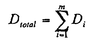
- the absolute value D A of cumulative dispersion in the positive dispersion optical fiber group A is assumed to be D 0 , and the standard deviation ⁇ A be ⁇ 0 .
- m be the number of optical cables 12
- D i [ps/nm] be the cumulative dispersion value of optical fibers contained in the i-th optical cable in the m pieces of optical cables 12.
- D total of each optical fiber line 11 contained in the optical transmission line 10 is expressed as:
- D total is distributed due to its statistical characteristic so as to yield an average value D ave of 0 [ps/nm] and a standard deviation ⁇ ave of m 1/2 ⁇ 0 [ps/nm] as shown in Fig. 4.
- D total is distributed due to its statistical characteristic so as to yield an average value D ave of +D 0 or -D 0 [ps/nm] depending on whether the positive dispersion optical fibers 14 or negative dispersion optical fibers 16 have a greater number, and a standard deviation ⁇ ave of m 1/2 ⁇ ⁇ 0 [ps/nm] as shown in Fig. 5.
- the positive dispersion optical fiber group A has an average value of dispersion of 3.5 [ps/nm/km] and a standard deviation of 0.5 [ps/nm/km].
- the negative dispersion optical fiber group B has an average value -D 0 of dispersion of -3.5 [ps/nm/km] and a standard deviation of 0.5 [ps/nm/km].
- the optical fibers contained in the positive dispersion optical fiber group A and negative dispersion optical fiber group B each have a length of 4 [km].
- the average value D 0 of cumulative dispersion of the positive dispersion optical fiber group A is 14 [ps/nm] and a standard deviation ⁇ 0 is 2 [ps/nm] at a wavelength of 1550 nm.
- the average value -D 0 of cumulative dispersion of the negative dispersion optical fiber group B is -14 [ps/nm] and a standard deviation ⁇ 0 is 2 [ps/nm] at a wavelength of 1550 nm.
- each optical fiber line 11 becomes 80 [km]. Then, the total cumulative dispersion value D total of each optical fiber line 11 is distributed so as to yield an average value D ave of 0 [ps/nm] and a standard deviation ⁇ ave of 8.9 [ps/nm/km].
- the length of optical fiber line 11 becomes 84 [km]. Then, the total cumulative dispersion value D total of each optical fiber line is distributed so as to yield an average value D ave of +14 or -14 [ps/nm] and a standard deviation ⁇ ave of 9.2 [ps/nm/km].
- each optical fiber becomes 2 [km] if the length of optical fiber line 11 is 82 [km], for example, the total cumulative dispersion value D total would not exceed the above-mentioned range of ⁇ 42 [ps/nm].
- each optical fiber line 11 may be studied while additionally taking account of fluctuations in the length of optical fibers.
- the optical transmission line 10 in accordance with this embodiment contains a plurality of optical fiber lines 11 in which the positive dispersion optical fibers 14 and the negative dispersion optical fibers 16 are alternately coupled.
- the optical transmission line 10 attains a configuration containing a plurality of optical fiber lines 11 which have a sufficiently small absolute value of dispersion and keep the absolute value of chromatic dispersion from locally becoming zero.
- pulse waveforms are prevented from deforming, and four-wave mixing is restrained from occurring, whereby the transmission quality of optical transmission line 10 can be enhanced, and the optical transmission line 10 can be constructed inexpensively.
- each of the positive dispersion optical fibers 14 is an optical fiber selected from the positive dispersion optical fiber group A whose cumulative dispersion conforms to a Gaussian distribution having an average value of D A (> 0) and a standard deviation of ⁇ A
- each of the negative dispersion optical fibers 16 is an optical fiber selected from the negative dispersion optical fiber group B whose cumulative dispersion conforms to a Gaussian distribution having an average value of D B ( ⁇ 0) and a standard deviation of ⁇ B .
- the cumulative dispersion in the optical fiber line 11 as a whole can fall within a predetermined range, whereby the transmission quality of optical transmission line 10 can be improved, and it is possible to construct the optical transmission line 10 suitable for large-capacity optical communications using a high bit rate and a wavelength division multiplexing system.
- the positive dispersion optical fiber 14 has a chromatic dispersion of 2 ps/nm/km or greater in the 1.55- ⁇ m wavelength band while the negative dispersion optical fiber 16 has a chromatic dispersion of -2 ps/nm/km or smaller in the 1.55- ⁇ m wavelength band in the optical transmission line 10 in accordance with this embodiment, then the absolute value of chromatic dispersion can be made locally greater. As a result, the effect of suppressing four-wave mixing enhances, and the transmission quality further improves.
- chromatic dispersion in the plurality of positive dispersion optical fibers 14 and the average value of chromatic dispersion in the plurality of negative dispersion optical fibers 16 have absolute values approximately identical to each other, then chromatic dispersion can become substantially zero in the whole optical fiber line 11 constituted by the positive dispersion optical fibers 14 and negative dispersion optical fibers 16 alternately coupled to each other. As a result, optical signal hardly deforms its pulse waveform, whereby the transmission quality further improves.
- the average value of dispersion slope in the plurality of positive dispersion optical fibers 14 and the average value of dispersion slope in the plurality of negative dispersion optical fibers 16 have polarities different from each other in the optical transmission line in accordance with this embodiment, a wavelength range in which the absolute value of chromatic dispersion becomes sufficiently small can be widened in the whole optical fiber line 11 constituted by the positive dispersion optical fibers 14 and negative dispersion optical fibers 16 alternately coupled to each other. As a result, the number of wavelengths subjected to wavelength division multiplexing can be enhanced, whereby a larger capacity is realized in optical communications.
- positive dispersion optical fiber 14 and negative dispersion optical fiber 16 each have an effective area exceeding 50 ⁇ m 2 in the optical transmission line 10 in accordance with this embodiment, nonlinear optical phenomena can be restrained from occurring.
- the ratio of the mode field diameter of the negative dispersion optical fiber 16 to the mode field diameter of the positive dispersion optical fiber 14 is at least 0.8 but not exceeding 1.2 in the optical transmission line 10 in accordance with this embodiment, loss can be lowered at the junction between the positive dispersion optical fiber 14 and negative dispersion optical fiber 16.
- the positive dispersion optical fiber 14 and negative dispersion optical fiber 16 each have a length of 5 km or shorter, and the optical fiber line 11 comprising a number of positive dispersion optical fibers 14 and negative dispersion optical fibers 16 alternately coupled to each other is constructed in the optical transmission line 10 in accordance with this embodiment, then the absolute value of chromatic dispersion in the optical fiber line 11 as a whole can sufficiently be made smaller in terms of statistics even when chromatic dispersion fluctuates more or less among the individual optical fibers.
- FIG. 6 is a view showing the configuration of the optical transmission line 30 in accordance with this embodiment.
- the optical transmission line 30 in accordance with this embodiment differs from the optical transmission line 10 in accordance with the first embodiment in the following points.
- a plurality of optical cables 12 each containing a plurality of positive dispersion optical fibers 14 and a plurality of negative dispersion optical fibers 16 are arranged adjacent each other in its longitudinal direction such that the positive dispersion optical fibers 14 and negative dispersion optical fibers 16 are coupled to each other.
- a positive dispersion optical cable 32 containing a plurality of positive dispersion optical fibers 14 and a negative dispersion optical cable 34 containing a plurality of negative dispersion optical fibers 16 are arranged adjacent each other in the longitudinal direction such that the positive dispersion optical fibers 14 and negative dispersion optical fibers 16 are coupled to each other.
- the number of positive dispersion optical fibers 14 contained in the positive dispersion optical cable 32 and the number of the negative dispersion optical fibers 16 contained in the negative dispersion optical cable 34 are identical to each other. Also, each of the positive dispersion optical fibers 14 and negative dispersion optical fibers 16 has substantially the same length, which is 5 km or shorter.
- a positive dispersion optical fiber group A containing a plurality of positive dispersion optical fibers 14 having a positive chromatic dispersion in the 1.55- ⁇ m wavelength band, which is a signal wavelength band, and a negative dispersion optical fiber group B containing a plurality of negative dispersion optical fibers 16 having a negative chromatic dispersion in the 1.55- ⁇ m wavelength band, which is a signal wavelength band, are prepared as shown in Fig. 2.
- the cumulative dispersion at a predetermined wavelength conforms to a Gaussian distribution having an average value of D A (> 0) and a standard deviation of ⁇ A .
- the cumulative dispersion at a predetermined wavelength conforms to a Gaussian distribution having an average value of D B ( ⁇ 0) and a standard deviation of ⁇ B .
- a plurality of positive dispersion optical fibers 14 are selected from the positive dispersion optical fiber group A, so as to produce the positive dispersion optical cable 32, whereas a plurality of negative dispersion optical fibers 16 are selected from the negative dispersion optical fiber group B, so as to produce the negative dispersion optical cable 34.
- the positive dispersion optical cable 32 and negative dispersion optical cable 34 made by the above-mentioned manufacturing method are alternately arranged adjacent each other in the longitudinal direction such that the positive dispersion optical fibers 14 contained in the positive dispersion optical cable 32 and the negative dispersion optical fibers 16 contained in the negative dispersion optical cable 34 are coupled to each other.
- the optical transmission line 30 in accordance with this embodiment contains a plurality of optical fiber lines 31 in which the positive dispersion optical fibers 14 and the negative dispersion optical fibers 16 are alternately coupled. Therefore, without any complicated manufacturing steps and difficult control, it attains a configuration containing a plurality of optical fiber lines 31 which have a sufficiently small absolute value of dispersion and keep the absolute value of chromatic dispersion from locally becoming zero. As a result, pulse waveforms are prevented from deforming, and four-wave mixing is restrained from occurring, whereby the transmission quality of optical transmission line 30 can be enhanced, and the optical transmission line 30 can be constructed inexpensively.
- each of the positive dispersion optical fibers 14 is an optical fiber selected from the positive dispersion optical fiber group A whose cumulative dispersion conforms to a Gaussian distribution having an average value of D A (> 0) and a standard deviation of ⁇ A
- each of the negative dispersion optical fibers 16 is an optical fiber selected from the negative dispersion optical fiber group B whose cumulative dispersion conforms to a Gaussian distribution having an average value of D B ( ⁇ 0) and a standard deviation of ⁇ B .
- the cumulative dispersion in the optical fiber line 31 as a whole can fall within a predetermined range, whereby the transmission quality of optical transmission line 30 can be improved, and it is possible to construct the optical transmission line 30 suitable for large-capacity optical communications using a high bit rate and a wavelength division multiplexing system.
- the optical transmission line 30 in accordance with this embodiment is constructed by use of a plurality of positive dispersion optical cables 32 each containing a plurality of positive dispersion optical fibers 14 and a plurality of negative dispersion optical cables 34 each containing a plurality of negative dispersion optical fibers 16, the positive dispersion optical fibers 14 and negative dispersion optical fibers 16 will naturally be coupled to each other if only the positive dispersion optical cables 32 and negative dispersion optical cables 34 are alternately arranged adjacent each other, and the respective optical fibers contained therein are coupled to each other. As a consequence, coupling errors (e.g., errors such as the coupling of positive dispersion optical fibers 14 to each other) can be prevented from occurring, whereby reliability and stability improve in the work of laying.
- coupling errors e.g., errors such as the coupling of positive dispersion optical fibers 14 to each other
- the optical fiber line of the present invention can attain a sufficiently small absolute value of cumulative chromatic dispersion in the optical fiber line as a whole and can keep the absolute value of chromatic dispersion from locally becoming zero.
- pulse waveforms are prevented from deforming, and four-wave mixing is restrained from occurring, whereby the transmission quality of optical fiber line can be enhanced, and the optical fiber line can be constructed inexpensively.
- each of the positive dispersion optical fibers is an optical fiber selected from a positive dispersion optical fiber group whose cumulative dispersion conforms to a distribution with an average value of D A (> 0) and a standard deviation of ⁇ A
- each of the negative dispersion optical fibers is an optical fiber selected from a negative dispersion optical fiber group whose cumulative dispersion conforms to a distribution with an average value of D B ( ⁇ 0) and a standard deviation of ⁇ B
- the cumulative dispersion in the optical fiber line as a whole can fall within a predetermined range if the average values D A and D B and the standard deviations ⁇ A and ⁇ B are appropriately adjusted, whereby the transmission quality of optical fiber line can improve, thus making it possible to construct the optical transmission line suitable for large-capacity optical communications using a high bit rate and a wavelength division multiplexing system.
Landscapes
- Physics & Mathematics (AREA)
- Chemical & Material Sciences (AREA)
- Dispersion Chemistry (AREA)
- Electromagnetism (AREA)
- Engineering & Computer Science (AREA)
- Computer Networks & Wireless Communication (AREA)
- Signal Processing (AREA)
- General Physics & Mathematics (AREA)
- Optics & Photonics (AREA)
- Optical Communication System (AREA)
Abstract
Description
| CHARACTERISTIC | POSITIVE | NEGATIVE |
| FIBER TYPE | DISPERSION-FLATTENED FIBER | DISPERSION-FLATTENED FIBER |
| EFFECTIVE AREA (m2) | 50 TO 55 | 50 TO 55 |
| CHROMATIC DISPERSION (ps/nm/km) | +2 TO +5 +2 TO +5 | -2 TO -5 -2 TO-5 |
| AVERAGE VALUE OF CHROMATIC DISPERSION (ps/nm/km) | +3.5 | -3.7 |
| DISPERSION SLOPE (ps/nm2/km) | +0.01 TO+0.03 | -0.01 TO +0.01 |
| AVERAGE VALUE OF DISPERSION SLOPE (ps/nm2/km) | +0.015 | -0.05 |
Claims (13)
- An optical fiber line comprising:a plurality of positive dispersion optical fibers, having a positive chromatic dispersion in a signal wavelength band, selected from a positive dispersion optical fiber group whose cumulative dispersion conforms to a distribution with an average value of DA (> 0) and a standard deviation of σA; anda plurality of negative dispersion optical fibers, having a negative chromatic dispersion in the signal wavelength band, selected from a negative dispersion optical fiber group whose cumulative dispersion conforms to a distribution with an average value of DB (< 0) and a standard deviation of σB;said positive and negative dispersion optical fibers being alternately arranged and coupled in a longitudinal direction.
- An optical fiber line according to claim 1, wherein each of said positive dispersion optical fibers has a chromatic dispersion of 2 ps/nm/km or greater, and wherein each of said negative dispersion optical fibers has a chromatic dispersion of -2 ps/nm/km or smaller.
- An optical fiber line according to claim 1, wherein the average value of dispersion slope in said plurality of positive dispersion optical fibers and the average value of dispersion slope in said plurality of negative dispersion optical fibers have polarities different from each other.
- An optical fiber line according to claim 1, wherein each of said positive dispersion optical fibers and negative dispersion optical fibers has an effective area exceeding 50 µm2.
- An optical fiber line according to claim 1, wherein the absolute value of dispersion slope in each of said positive dispersion optical fibers and the absolute value of dispersion slope in each of said negative dispersion optical fibers are each smaller than 0.03 ps/nm2/km.
- An optical fiber line according to claim 1, wherein the ratio of the mode field diameter of any of said negative dispersion optical fibers to the mode field diameter of any of said positive dispersion optical fibers is at least 0.8 but not exceeding 1.2.
- An optical fiber line according to claim 1, wherein each of said positive dispersion optical fibers and negative dispersion optical fibers has a length of 5 km or shorter.
- An optical transmission line containing a plurality of optical fiber lines according to claim 1,said optical transmission line comprising a plurality of optical cables arranged adjacent each other in a longitudinal direction; each said optical cable containing a plurality of positive dispersion optical fibers, having a positive chromatic dispersion in a signal wavelength band, selected from a positive dispersion optical fiber group whose cumulative dispersion conforms to a distribution with an average value of DA (> 0) and a standard deviation of σA and a plurality of negative dispersion optical fibers, having a negative chromatic dispersion in the signal wavelength band, selected from a negative dispersion optical fiber group whose cumulative dispersion conforms to a distribution with an average value of DB (< 0) and a standard deviation of σB;wherein, in first and second optical cables adjacent each other selected from said optical cables, said positive dispersion optical fibers contained in said first optical cable and said negative dispersion optical fibers contained in said second optical cable are coupled to each other, whereas said negative dispersion optical fibers contained in said first optical cable and said positive dispersion optical fibers contained in said second optical cable are coupled to each other.
- An optical transmission line containing a plurality of optical fiber lines according to claim 1,said optical transmission line comprising a positive dispersion optical cable and a negative dispersion optical cable which are alternately arranged adjacent each other in a longitudinal direction; said positive dispersion optical cable containing a plurality of positive dispersion optical fibers, having a positive chromatic dispersion in a signal wavelength band, selected from a positive dispersion optical fiber group whose cumulative dispersion conforms to a distribution with an average value of DA (> 0) and a standard deviation of σA; said negative dispersion optical cable containing a plurality of negative dispersion optical fibers, having a negative chromatic dispersion in the signal wavelength band, selected from a negative dispersion optical fiber group whose cumulative dispersion conforms to a distribution with an average value of DB (< 0) and a standard deviation of σB;wherein said positive dispersion optical fibers contained in said positive dispersion optical cable and said negative dispersion optical fibers contained in said negative dispersion optical cable are coupled to each other.
- A method of making an optical cable in which the optical cables provided in the optical transmission line according to claim 8 are made, said method comprising the steps of:selecting a plurality of positive dispersion optical fibers having a positive chromatic dispersion in a signal wavelength band from a positive dispersion optical fiber group whose cumulative dispersion conforms to a distribution with an average value of DA (> 0) and a standard deviation of σA;selecting a plurality of negative dispersion optical fibers having a negative chromatic dispersion in the signal wavelength band from a negative dispersion optical fiber group whose cumulative dispersion conforms to a distribution with an average value of DB (< 0) and a standard deviation of σB; andusing said plurality of positive dispersion optical fibers and said plurality of negative dispersion optical fibers so as to make a plurality of optical cables each containing positive and negative dispersion optical fibers.
- A method of making an optical cable in which the positive dispersion optical cable and negative dispersion optical cable provided in the optical transmission line according to claim 9 are made, said method comprising the steps of:selecting a plurality of positive dispersion optical fibers having a positive chromatic dispersion in a signal wavelength band from a positive dispersion optical fiber group whose cumulative dispersion conforms to a distribution with an average value of DA (> 0) and a standard deviation of σA;selecting a plurality of negative dispersion optical fibers having a negative chromatic dispersion in the signal wavelength band from a negative dispersion optical fiber group whose cumulative dispersion conforms to a distribution with an average value of DB (< 0) and a standard deviation of σB; andusing said positive dispersion optical fiber so as to make a positive dispersion optical cable, and using said negative dispersion optical fiber so as to make a negative dispersion optical cable.
- A method of laying the optical transmission line according to claim 8, said method comprising the steps of:preparing a plurality of optical cables; each said optical cable containing a plurality of positive dispersion optical fibers, having a positive chromatic dispersion in a signal wavelength band, selected from a positive dispersion optical fiber group whose cumulative dispersion conforms to a distribution with an average value of DA (> 0) and a standard deviation of σA and a plurality of negative dispersion optical fibers, having a negative chromatic dispersion in the signal wavelength band, selected from a negative dispersion optical fiber group whose cumulative dispersion conforms to a distribution with an average value of DB (< 0) and a standard deviation of σB; andarranging said optical cables adjacent each other in a longitudinal directionsuch that, in first and second optical cables adjacent each other in said optical cables, said positive dispersion optical fibers contained in said first optical cable and said negative dispersion optical fibers contained in said second optical cable are coupled to each other, whereas said negative dispersion optical fibers contained in said first optical cable and said positive dispersion optical fibers contained in said second optical cable are coupled to each other.
- A method of laying the optical transmission line according to claim 9, said method comprising the steps of:preparing a positive dispersion optical cable containing a plurality of positive dispersion optical fibers, having a positive chromatic dispersion in a signal wavelength band, selected from a positive dispersion optical fiber group whose cumulative dispersion conforms to a distribution with an average value of DA (> 0) and a standard deviation of σA;preparing a negative dispersion optical cable containing a plurality of negative dispersion optical fibers, having a negative chromatic dispersion in the signal wavelength band, selected from a negative dispersion optical fiber group whose cumulative dispersion conforms to a distribution with an average value of DB (< 0) and a standard deviation of σB; andalternately arranging said positive and negative dispersion optical cables in a longitudinal directionsuch that said positive dispersion optical fibers contained in said positive dispersion optical cable and said negative dispersion optical fibers contained in said negative dispersion optical cable are coupled to each other.
Applications Claiming Priority (3)
| Application Number | Priority Date | Filing Date | Title |
|---|---|---|---|
| JP25158099 | 1999-09-06 | ||
| JP25158099 | 1999-09-06 | ||
| PCT/JP2000/005713 WO2001018572A1 (en) | 1999-09-06 | 2000-08-24 | Optical fiber line, optical transmission line, production method of optical cables and method of laying optical transmission lines |
Publications (2)
| Publication Number | Publication Date |
|---|---|
| EP1136850A1 true EP1136850A1 (en) | 2001-09-26 |
| EP1136850A4 EP1136850A4 (en) | 2003-01-15 |
Family
ID=17224939
Family Applications (1)
| Application Number | Title | Priority Date | Filing Date |
|---|---|---|---|
| EP00954995A Ceased EP1136850A4 (en) | 1999-09-06 | 2000-08-24 | OPTICAL FIBER LINE, OPTICAL TRANSMISSION LINE, MANUFACTURING METHOD OF OPTICAL CABLES AND METHOD FOR LAYING OPTICAL TRANSMISSION LINE |
Country Status (3)
| Country | Link |
|---|---|
| US (1) | US6567595B1 (en) |
| EP (1) | EP1136850A4 (en) |
| WO (1) | WO2001018572A1 (en) |
Cited By (2)
| Publication number | Priority date | Publication date | Assignee | Title |
|---|---|---|---|---|
| EP1251378A3 (en) * | 2001-04-16 | 2004-01-14 | KDDI Submarine Cable Systems Inc. | Manufacturing method of optical fiber cable |
| WO2005064370A1 (en) * | 2003-12-30 | 2005-07-14 | Prysmian Cavi E Sistemi Energia S.R.L. | Low polarisation mode dispersion (pmd) optical fiber link, and method of making the same |
Families Citing this family (5)
| Publication number | Priority date | Publication date | Assignee | Title |
|---|---|---|---|---|
| JP4122699B2 (en) | 2000-09-29 | 2008-07-23 | 住友電気工業株式会社 | Dispersion management optical transmission line and its configuration method |
| JP4626127B2 (en) * | 2003-04-09 | 2011-02-02 | 住友電気工業株式会社 | Optical transmission line configuration method |
| JP2012203036A (en) * | 2011-03-23 | 2012-10-22 | Mitsubishi Cable Ind Ltd | Optical transmission line |
| CN110382079B (en) * | 2017-10-17 | 2021-09-10 | 株式会社村田制作所 | Filter member and air conditioning apparatus |
| CN113050242B (en) * | 2019-12-28 | 2022-07-12 | 华为技术有限公司 | Transmission cable |
Family Cites Families (13)
| Publication number | Priority date | Publication date | Assignee | Title |
|---|---|---|---|---|
| FR2681145A1 (en) * | 1991-09-06 | 1993-03-12 | Alcatel Cable | LARGE DISTANCE OPTICAL COMMUNICATION LINE AND METHOD FOR PRODUCING THE SAME |
| JPH08286219A (en) * | 1995-02-13 | 1996-11-01 | Nippon Telegr & Teleph Corp <Ntt> | Optical soliton transmission line and optical soliton transmission method |
| GB2299473A (en) * | 1995-03-27 | 1996-10-02 | Hitachi Cable | Broadband long-distance optical fibre communications |
| AU693329B2 (en) * | 1995-04-13 | 1998-06-25 | Corning Incorporated | Dispersion managed optical waveguide |
| GB9524203D0 (en) * | 1995-11-27 | 1996-01-31 | British Tech Group | Optical communications |
| CA2195614C (en) * | 1996-02-16 | 2005-06-28 | George F. Wildeman | Symmetric, dispersion-manager fiber optic cable and system |
| US5764841A (en) * | 1996-04-25 | 1998-06-09 | Nippon Telegraph And Telephone Corporation | Optical fiber transmission line, optical fiber transmission system and production method thereof, and optical fiber combining method |
| US5611016A (en) * | 1996-06-07 | 1997-03-11 | Lucent Technologies Inc. | Dispersion-balanced optical cable |
| US5887105A (en) * | 1997-04-28 | 1999-03-23 | Corning Incorporated | Dispersion managed optical fiber |
| JP3786761B2 (en) * | 1997-07-11 | 2006-06-14 | 株式会社フジクラ | Low dispersion optical fiber and manufacturing method thereof |
| CA2277409C (en) * | 1998-07-10 | 2003-02-11 | Nippon Telegraph And Telephone Corporation | Optical transmission system |
| FR2788180B1 (en) * | 1999-01-04 | 2004-01-30 | Cit Alcatel | WAVELENGTH MULTIPLEXED FIBER OPTIC TRANSMISSION SYSTEM |
| JP3653719B2 (en) * | 1999-09-09 | 2005-06-02 | 住友電気工業株式会社 | Optical fiber transmission line |
-
2000
- 2000-08-24 EP EP00954995A patent/EP1136850A4/en not_active Ceased
- 2000-08-24 WO PCT/JP2000/005713 patent/WO2001018572A1/en not_active Ceased
- 2000-09-05 US US09/655,718 patent/US6567595B1/en not_active Expired - Fee Related
Cited By (4)
| Publication number | Priority date | Publication date | Assignee | Title |
|---|---|---|---|---|
| EP1251378A3 (en) * | 2001-04-16 | 2004-01-14 | KDDI Submarine Cable Systems Inc. | Manufacturing method of optical fiber cable |
| WO2005064370A1 (en) * | 2003-12-30 | 2005-07-14 | Prysmian Cavi E Sistemi Energia S.R.L. | Low polarisation mode dispersion (pmd) optical fiber link, and method of making the same |
| CN100437169C (en) * | 2003-12-30 | 2008-11-26 | 普雷斯曼电缆及系统能源有限公司 | Low Polarization Mode Dispersion (PMD) optical fiber link and method of making same |
| US7534055B2 (en) | 2003-12-30 | 2009-05-19 | Prysmian Cavi E Sistemi Energia S.R.L. | Low polarisation mode dispersion (PMD) optical fiber link, and method of making the same |
Also Published As
| Publication number | Publication date |
|---|---|
| EP1136850A4 (en) | 2003-01-15 |
| US6567595B1 (en) | 2003-05-20 |
| WO2001018572A1 (en) | 2001-03-15 |
Similar Documents
| Publication | Publication Date | Title |
|---|---|---|
| US6490398B2 (en) | Dispersion-compensating fiber having a high figure of merit | |
| CN1105926C (en) | High capacity optical fiber network | |
| US6654531B2 (en) | Dispersion-compensating module | |
| EP1043609A1 (en) | Dispersion compensation optical fiber and wavelength multiplex optical transmission line comprising dispersion compensation optical fiber | |
| US20130209106A1 (en) | Optical transmission system, multi-core optical fiber, and method of manufacturing multi-core optical fiber | |
| AU776945B2 (en) | Optical fiber and optical transmission line comprising the same | |
| JPH1062639A (en) | Dispersion balanced optical fiber cable | |
| US6498887B1 (en) | Dispersion-compensating fiber having a high relative dispersion slope | |
| US6684016B2 (en) | Optical fiber for wavelength division multiplexing optical transmission system using densely spaced optical channels | |
| AU783864B2 (en) | Dispersion compensation system | |
| US6567595B1 (en) | Optical fiber line, optical transmission line, method of making optical cable, and method of laying optical transmission line | |
| US7164829B2 (en) | Optical fiber, optical transmission line and optical communications system | |
| US20020164117A1 (en) | Optical fiber transmission-line | |
| US6668121B2 (en) | Optical fiber, and dispersion compensator using same, optical transmission line using same and optical transmission system using same | |
| US6876803B2 (en) | Optical transmission system | |
| US6795608B2 (en) | Optical communication link | |
| US6483970B2 (en) | Fiber optic cable and optical transmission system | |
| US6813425B1 (en) | Fiber optic cable for increased transmission capacity and wavelength division multiplexing optical transmission system using the same | |
| JP3767468B2 (en) | Dispersion and dispersion slope compensation optical transmission line and optical transmission system | |
| JP5133646B2 (en) | Dispersion compensation optical fiber design method | |
| JPWO2001018572A1 (en) | Optical fiber line, optical transmission line, optical cable manufacturing method, and optical transmission line installation method | |
| EP1675285A1 (en) | Dispersion management for low dispersion fibers in DWDM core networks | |
| HK1042751A (en) | Optical fiber, and dispersion compensator using same, optical transmission line using same and optical transmission system using same | |
| JP2000209154A (en) | Transmission system for wavelength multiplexed optical fiber |
Legal Events
| Date | Code | Title | Description |
|---|---|---|---|
| PUAI | Public reference made under article 153(3) epc to a published international application that has entered the european phase |
Free format text: ORIGINAL CODE: 0009012 |
|
| 17P | Request for examination filed |
Effective date: 20010521 |
|
| AK | Designated contracting states |
Kind code of ref document: A1 Designated state(s): AT BE CH CY DE DK ES FI FR GB GR IE IT LI LU MC NL PT SE Kind code of ref document: A1 Designated state(s): DE FR GB IT |
|
| A4 | Supplementary search report drawn up and despatched |
Effective date: 20021129 |
|
| AK | Designated contracting states |
Kind code of ref document: A4 Designated state(s): DE FR GB IT |
|
| RIC1 | Information provided on ipc code assigned before grant |
Free format text: 7G 02B 6/44 A, 7G 02B 6/16 B, 7H 04B 10/18 B |
|
| 17Q | First examination report despatched |
Effective date: 20030522 |
|
| RBV | Designated contracting states (corrected) |
Designated state(s): DE FR GB IT |
|
| APBN | Date of receipt of notice of appeal recorded |
Free format text: ORIGINAL CODE: EPIDOSNNOA2E |
|
| APBR | Date of receipt of statement of grounds of appeal recorded |
Free format text: ORIGINAL CODE: EPIDOSNNOA3E |
|
| APAF | Appeal reference modified |
Free format text: ORIGINAL CODE: EPIDOSCREFNE |
|
| APAF | Appeal reference modified |
Free format text: ORIGINAL CODE: EPIDOSCREFNE |
|
| APBT | Appeal procedure closed |
Free format text: ORIGINAL CODE: EPIDOSNNOA9E |
|
| STAA | Information on the status of an ep patent application or granted ep patent |
Free format text: STATUS: THE APPLICATION HAS BEEN REFUSED |
|
| 18R | Application refused |
Effective date: 20070613 |