EP1136772A2 - Air-conditioning refrigerant receiver - Google Patents
Air-conditioning refrigerant receiver Download PDFInfo
- Publication number
- EP1136772A2 EP1136772A2 EP01107059A EP01107059A EP1136772A2 EP 1136772 A2 EP1136772 A2 EP 1136772A2 EP 01107059 A EP01107059 A EP 01107059A EP 01107059 A EP01107059 A EP 01107059A EP 1136772 A2 EP1136772 A2 EP 1136772A2
- Authority
- EP
- European Patent Office
- Prior art keywords
- casing
- refrigerant
- guide tube
- lower cover
- annular clearance
- Prior art date
- Legal status (The legal status is an assumption and is not a legal conclusion. Google has not performed a legal analysis and makes no representation as to the accuracy of the status listed.)
- Granted
Links
Images


Classifications
-
- F—MECHANICAL ENGINEERING; LIGHTING; HEATING; WEAPONS; BLASTING
- F25—REFRIGERATION OR COOLING; COMBINED HEATING AND REFRIGERATION SYSTEMS; HEAT PUMP SYSTEMS; MANUFACTURE OR STORAGE OF ICE; LIQUEFACTION SOLIDIFICATION OF GASES
- F25B—REFRIGERATION MACHINES, PLANTS OR SYSTEMS; COMBINED HEATING AND REFRIGERATION SYSTEMS; HEAT PUMP SYSTEMS
- F25B43/00—Arrangements for separating or purifying gases or liquids; Arrangements for vaporising the residuum of liquid refrigerant, e.g. by heat
- F25B43/006—Accumulators
-
- F—MECHANICAL ENGINEERING; LIGHTING; HEATING; WEAPONS; BLASTING
- F25—REFRIGERATION OR COOLING; COMBINED HEATING AND REFRIGERATION SYSTEMS; HEAT PUMP SYSTEMS; MANUFACTURE OR STORAGE OF ICE; LIQUEFACTION SOLIDIFICATION OF GASES
- F25B—REFRIGERATION MACHINES, PLANTS OR SYSTEMS; COMBINED HEATING AND REFRIGERATION SYSTEMS; HEAT PUMP SYSTEMS
- F25B43/00—Arrangements for separating or purifying gases or liquids; Arrangements for vaporising the residuum of liquid refrigerant, e.g. by heat
- F25B43/003—Filters
Definitions
- the present invention relates to an improvement in an air-conditioning refrigerant receiver used in an air conditioner such as a car air conditioner.
- Such air-conditioning refrigerant receivers are conventionally known from Japanese Patent Application Laid-open No.10-238906 and the like.
- an annular clearance is defined between an outer periphery of a lower cover supporting the contained assembly from the below and an inner periphery of a casing, so that the refrigerant, which has passed through the contained assembly, is permitted to quietly flow down along the inner surface of the casing through the annular clearance.
- the lower cover is formed into a mere circular flat plate shape, and the annular clearance is made at a length corresponding to a thickness of the lower cover.
- an air-conditioning refrigerant receiver comprising a contained assembly comprised of an upper filter, a desiccant and a lower filter, which are laminated one on another, the contained assembly being sandwiched between upper and lower covers and fixed within a casing, the casing having a refrigerant supply passage and a refrigerant discharge passage provided therein, the refrigerant supply passage leading to an upper space defined within the casing above the upper cover, and the refrigerant discharge passage leading to a lower space defined within the casing below the lower cover, an annular clearance being defined between an outer periphery of the lower cover and an inner periphery of the casing for guiding a refrigerant, which has passed through the contained assembly downwards from the above, into the lower space, wherein the refrigerant receiver further includes a guide tube, which extends downwards to define an annular passage connected to the annular clearance between the guide tube and an inner surface of the casing, the guide tube being connected
- the refrigerant, which has passed through the contained assembly flows through the annular clearance to the lower space within the casing.
- the refrigerant, which has passed through the annular clearance can be guided to a lower portion by the guide tube so as to quietly flow down along the inner surface of the casing, because the guide tube extending downwards and defining the annular passage connected to the annular clearance between the guide tube and the inner surface of the casing is connected at its upper end to the outer periphery of the lower cover defining the annular clearance between the lower cover and the inner periphery of the casing.
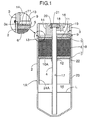
- Fig.1 shows a refrigerant receiver according to a first embodiment of the present invention.
- the refrigerant receiver has a casing 1A comprising a bottomed cylindrical casing body 2 with its lower end closed, and a disk-shaped head 3 closing an opening at an upper end of the casing body 2.
- a ring-shaped projection 3a protruding on a lower surface of the head 3 is fitted into an upper end of the casing body 2, and an outer peripheral portion of a lower end of the head 3 and an outer peripheral portion of an upper end of the casing body 2 are welded to each other.
- the head 3 is formed by forging, and integrally provided with a cylindrical portion 4 disposed coaxially within the casing body 2.
- An upper cover 9, an upper filter 5, a desiccant 6, a lower filter 7 and a lower cover 10A are accommodated in a vertically superposed manner in an upper portion of the casing 1A.
- the upper filter 5, the desiccant 6 and the lower filter 7 form a contained assembly 8, which is sandwiched between the upper cover 9 and the lower cover 10A from the above and below.
- the upper cover 9 is formed into a flat plate-shape having a large number of punched bores 11 and put into abutment against the projection 3a of the head 3 in such a manner that its outer periphery is fitted to the casing body 2 and the cylindrical portion 4 is fitted to its inner periphery.
- the contained assembly 8 is put into abutment against a lower surface of the lower cover 10A in such a manner that its outer periphery is fitted to the casing body 2 and the cylindrical portion 4 is fitted to its inner periphery.
- the lower cover 10A is formed into a flat plate shape having a flange portion 12 formed by folding its inner periphery downwards.
- the flange portion 12 is caulked to the cylindrical portion 4 at a location at which the lower cover 10A with the cylindrical portion 4 fitted to the flange portion 12 abuts against a lower surface of the contained assembly 8.
- the contained assembly 8 is clamped between the upper cover 9 abutting against the projection 3a of the head 3 and the lower cover 10A fixed in the caulked manner to the cylindrical portion 4.
- An upper space 13 is defined in the casing 1A above the upper cover 9, and a refrigerant supply passage 14 for supplying a refrigerant into the upper space 13 is provided in the head 3.
- a condenser of an air conditioner is connected to the refrigerant supply passage 14. The refrigerant introduced from the condenser via the refrigerant supply passage 14 into the upper space 13 flows through the punched bores 11 in the upper cover 9 toward the contained assembly 8.
- a lower space 15 is defined in the casing 1A below the lower cover 10, and a refrigerant discharge passage 16 is provided in the casing 1A to lead to the lower space 15.
- the refrigerant discharge passage 16 comprises a passage section 17 defined within the cylindrical portion 4 integral with the head 3 to extend vertically, a passage section 18 provided in the head 3 to extend sideways from an upper portion of the passage section 17, and a passage section 19 provided in the head 3 to extend upwards from a portion of the passage section 18 close to an outer end.
- the refrigerant discharge passage 16 is connected to an expansion valve of the air conditioner.
- the refrigerant is stored in the lower space 15, and the lower end of the cylindrical portion 4, i.e., the lower end of the refrigerant discharge passage 16 is set to lie below the level L of the refrigerant in the lower space 15.
- a sight glass 21 is mounted to the head 3 immediately above the cylindrical portion 4 with a seal member 20 interposed therebetween, and the situation of the refrigerant within the lower space 15 can be viewed through the sight glass 21.
- An annular clearance 22 is defined between the outer periphery of the lower cover 10A and the inner periphery of the casing body 2 of the casing 1A, and a guide tube 24A extends downwards to define an annular passage 23 connected to the annular clearance 22 between the guide tube 24A and an inner surface of the casing body 2 of the casing 1A, and is integrally connected at its upper end to the outer periphery of the lower cover 10A.
- a lower end of the guide tube 24A is set at a location above and close to the level L of the refrigerant in the lower space 15.
- the refrigerant liquefied in the condenser of the air conditioner is introduced through the refrigerant supply passage 14 into the upper space 13 within the casing 1A and further flows via the punched bores 11 in the upper cover 9 toward the contained assembly 8. Dusts in the refrigerant flowing downwards within the contained assembly 8 are removed in the upper and lower filters 5 and 7, and water in refrigerant is removed by the desiccant 6.
- the refrigerant flowing downwards within the contained assembly 8 flows via the annular clearance 22 toward the lower space 15.
- the refrigerant, which has passed through the annular clearance 22 can be guided to a lower portion in the guide tube 24A, so that it quietly flows along the inner surface of the casing body 2, because the guide tube 24A extending downwards to define the annular passage 23 connected to the annular clearance 22 between the guide tube 24A and the inner surface of the casing body 2 is connected at its upper end to the outer periphery of the lower cover 10A defining the annular clearance 22 between the lower cover 10A and the inner periphery of the casing 1A. Therefore, it is possible to inhibit to the utmost the refrigerant from being separated from the inner surface of the casing body 2 to become scattered, thereby more reliably preventing the occurrence of bubbling.
- Fig. 2 shows a second embodiment of the present invention.
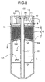
- a lower end of a guide tube 24B connected to the outer periphery of the lower cover 10A may be set at a location lower than the level L of a refrigerant stored in the lower space 15.
- a lower cover 10B may be formed into such an umbrella shape that its diameter is smaller at a higher location.
- a plurality of notches 25 may be provided in a lower end of a guide tube 24B placed at a location lower than the level L of a refrigerant within the lower space 15. According to the fourth embodiment, it is possible to prevent to the utmost bubbles produced in the lower end of the annular passage 23 from entering into the guide tube 24B, thereby more reliably preventing the bubbles from being supplied to the expansion valve.
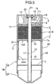
- Fig.5 shows a fifth embodiment of the present invention.
- a downward folded portion 7a is formed on an outer periphery of a lower filter 7 and fitted into an annular clearance 22 between an inner periphery of a casing 1B and the lower cover 10A.
- the casing 1B is comprised of a casing body 28 formed by forging and integrally provided with a head 3, an outer shell 26 connected to an outer periphery of a lower end of the head 3, and an inner shell 27 formed into the same shape as the cylindrical portion 4 in each of the first to fourth embodiments and connected at its upper end to a central portion of a lower end of the head 3; and a lid member 29 welded to the outer shell 26 to close a lower end of the outer shell 26.
- the annular clearance 22 and an annular passage 23 are defined between an inner periphery of the outer shell 26 and outer peripheries of the lower cover 10A and the guide tube 24A.
- a guide tube extends downwards to define an annular passage connected to the annular clearance between the guide tube and an inner surface of the casing, and is connected at its upper end to an outer periphery of the lower cover.
Landscapes
- Engineering & Computer Science (AREA)
- Chemical & Material Sciences (AREA)
- Analytical Chemistry (AREA)
- Power Engineering (AREA)
- Physics & Mathematics (AREA)
- Mechanical Engineering (AREA)
- Thermal Sciences (AREA)
- General Engineering & Computer Science (AREA)
- Air-Conditioning For Vehicles (AREA)
- Applications Or Details Of Rotary Compressors (AREA)
- Drying Of Gases (AREA)
Abstract
Description
Claims (1)
- An air-conditioning refrigerant receiver comprising a contained assembly comprised of an upper filter, a desiccant and a lower filter, which are laminated one on another, said contained assembly being sandwiched between upper and lower covers and fixed within a casing, said casing having a refrigerant supply passage and a refrigerant discharge passage provided therein, said refrigerant supply passage leading to an upper space defined within said casing above said upper cover, and said refrigerant discharge passage leading to a lower space defined within said casing below said lower cover, an annular clearance being defined between an outer periphery of said lower cover and an inner periphery of said casing for guiding a refrigerant, which has passed through said contained assembly downwards from the above, into said lower space, wherein said refrigerant receiver further includes a guide tube, which extends downwards to define an annular passage connected to said annular clearance between said guide tube and an inner surface of said casing, said guide tube being connected at an upper end thereof to an outer periphery of said lower cover.
Applications Claiming Priority (2)
| Application Number | Priority Date | Filing Date | Title |
|---|---|---|---|
| JP2000084712A JP3894701B2 (en) | 2000-03-22 | 2000-03-22 | Refrigerant receiver for air conditioning |
| JP2000084712 | 2000-03-22 |
Publications (3)
| Publication Number | Publication Date |
|---|---|
| EP1136772A2 true EP1136772A2 (en) | 2001-09-26 |
| EP1136772A3 EP1136772A3 (en) | 2001-11-28 |
| EP1136772B1 EP1136772B1 (en) | 2004-07-28 |
Family
ID=18601156
Family Applications (1)
| Application Number | Title | Priority Date | Filing Date |
|---|---|---|---|
| EP01107059A Expired - Lifetime EP1136772B1 (en) | 2000-03-22 | 2001-03-21 | Air-conditioning refrigerant receiver |
Country Status (4)
| Country | Link |
|---|---|
| US (1) | US6449978B2 (en) |
| EP (1) | EP1136772B1 (en) |
| JP (1) | JP3894701B2 (en) |
| DE (1) | DE60104462T2 (en) |
Families Citing this family (4)
| Publication number | Priority date | Publication date | Assignee | Title |
|---|---|---|---|---|
| US6692556B2 (en) * | 2001-10-29 | 2004-02-17 | Stanhope Products Co. | Desiccant cartridge with elongated center tube |
| US6560986B1 (en) * | 2002-03-07 | 2003-05-13 | Jeffrey K. Welch | Refrigeration valve and system |
| JP4091416B2 (en) * | 2002-12-27 | 2008-05-28 | 昭和電工株式会社 | Receiver tank for refrigeration cycle, heat exchanger with receiver tank, and condensing device for refrigeration cycle |
| FR3032267A1 (en) * | 2015-01-30 | 2016-08-05 | Valeo Systemes Thermiques | ASSEMBLY COMPRISING A BOTTLE FOR A HEAT EXCHANGER, IN PARTICULAR HEAT EXCHANGER FOR A MOTOR VEHICLE, AND A HEAT EXCHANGER CONTAINING SUCH AN ASSEMBLY. |
Family Cites Families (13)
| Publication number | Priority date | Publication date | Assignee | Title |
|---|---|---|---|---|
| US2835114A (en) | 1956-03-23 | 1958-05-20 | Philco Corp | Refrigeration apparatus |
| FR2552212B1 (en) * | 1983-09-16 | 1986-03-21 | Elf Aquitaine | METHOD AND DEVICE FOR OVERHEATING A REFRIGERATION FLUID |
| US4707999A (en) * | 1985-02-25 | 1987-11-24 | Nippondenso Co., Ltd. | Receiver for refrigerant apparatus |
| US4768355A (en) | 1987-01-27 | 1988-09-06 | Ford Motor Company | Accumulator with refrigerant processing cartridge for automotive air conditioning system |
| US4756166A (en) * | 1987-11-13 | 1988-07-12 | General Motors Corporation | Integral receiver/dehydrator and expansion valve for air conditioning systems |
| US4811571A (en) * | 1988-03-28 | 1989-03-14 | Thermo King Corporation | Refrigerant drier |
| JPH02100176A (en) | 1988-10-06 | 1990-04-12 | Mitsubishi Electric Corp | Translation method |
| US5184479A (en) * | 1991-12-23 | 1993-02-09 | Ford Motor Company | Accumulator for vehicle air conditioning system |
| JP3299467B2 (en) | 1997-02-26 | 2002-07-08 | 株式会社ケーヒン | Refrigerant receiver for air conditioning |
| US5787729A (en) * | 1997-06-04 | 1998-08-04 | Automotive Fluid Systems, Inc. | Accumulator deflector |
| DE29710638U1 (en) | 1997-06-18 | 1997-08-14 | Deutsche Controls GmbH, 80637 München | Receiving container for a lingerie batch |
| US6062039A (en) * | 1998-01-07 | 2000-05-16 | Parker-Hannifin Corporation | Universal accumulator for automobile air conditioning systems |
| US6223555B1 (en) * | 1999-06-08 | 2001-05-01 | Visteon Global Technologies, Inc. | Accumulator for an air conditioning system |
-
2000
- 2000-03-22 JP JP2000084712A patent/JP3894701B2/en not_active Expired - Fee Related
-
2001
- 2001-03-21 DE DE60104462T patent/DE60104462T2/en not_active Expired - Lifetime
- 2001-03-21 US US09/813,295 patent/US6449978B2/en not_active Expired - Fee Related
- 2001-03-21 EP EP01107059A patent/EP1136772B1/en not_active Expired - Lifetime
Also Published As
| Publication number | Publication date |
|---|---|
| EP1136772A3 (en) | 2001-11-28 |
| JP2001263868A (en) | 2001-09-26 |
| US20010037658A1 (en) | 2001-11-08 |
| US6449978B2 (en) | 2002-09-17 |
| DE60104462T2 (en) | 2004-12-02 |
| DE60104462D1 (en) | 2004-09-02 |
| JP3894701B2 (en) | 2007-03-22 |
| EP1136772B1 (en) | 2004-07-28 |
Similar Documents
| Publication | Publication Date | Title |
|---|---|---|
| US6223555B1 (en) | Accumulator for an air conditioning system | |
| US4827725A (en) | Suction accumulator with dirt trap | |
| US4627247A (en) | Suction accumulator | |
| US5076071A (en) | Suction accumulator with dirt trap and filter | |
| JP2009202703A (en) | Fuel shut-off valve | |
| KR20110073215A (en) | Expansion valve | |
| EP1136772B1 (en) | Air-conditioning refrigerant receiver | |
| US20030094456A1 (en) | Tank cap | |
| EP1541943A2 (en) | Gas liquid separator | |
| KR20130113364A (en) | Expansion valve | |
| JP4257027B2 (en) | Liquid tank | |
| US5613477A (en) | Evaporative fuel treatment device | |
| CN212390662U (en) | Gas-liquid separator and automobile air conditioning system | |
| US20060196219A1 (en) | Accumulator with full-flow filtering | |
| JP2005153773A (en) | Receiver dryer fitted with relief valve | |
| JPH05196325A (en) | accumulator | |
| JP6767099B2 (en) | accumulator | |
| JPH094945A (en) | Receiver dryer | |
| CN210372033U (en) | A solenoid valve and automobile braking system | |
| CN210602365U (en) | Gas-liquid separator and compressor | |
| JP3299467B2 (en) | Refrigerant receiver for air conditioning | |
| JP3146279B2 (en) | Liquid tank | |
| EP3734195B1 (en) | Liquid storage container and manufacturing method thereof | |
| JP3409193B2 (en) | Liquid receiver | |
| CN211854548U (en) | Gas-liquid separator, filter screen structure and filter screen support thereof |
Legal Events
| Date | Code | Title | Description |
|---|---|---|---|
| PUAI | Public reference made under article 153(3) epc to a published international application that has entered the european phase |
Free format text: ORIGINAL CODE: 0009012 |
|
| AK | Designated contracting states |
Kind code of ref document: A2 Designated state(s): DE GB Kind code of ref document: A2 Designated state(s): AT BE CH CY DE DK ES FI FR GB GR IE IT LI LU MC NL PT SE TR |
|
| AX | Request for extension of the european patent |
Free format text: AL;LT;LV;MK;RO;SI |
|
| PUAL | Search report despatched |
Free format text: ORIGINAL CODE: 0009013 |
|
| AK | Designated contracting states |
Kind code of ref document: A3 Designated state(s): AT BE CH CY DE DK ES FI FR GB GR IE IT LI LU MC NL PT SE TR |
|
| AX | Request for extension of the european patent |
Free format text: AL;LT;LV;MK;RO;SI |
|
| 17P | Request for examination filed |
Effective date: 20020206 |
|
| AKX | Designation fees paid |
Free format text: DE GB |
|
| GRAP | Despatch of communication of intention to grant a patent |
Free format text: ORIGINAL CODE: EPIDOSNIGR1 |
|
| GRAS | Grant fee paid |
Free format text: ORIGINAL CODE: EPIDOSNIGR3 |
|
| GRAA | (expected) grant |
Free format text: ORIGINAL CODE: 0009210 |
|
| AK | Designated contracting states |
Kind code of ref document: B1 Designated state(s): DE GB |
|
| REG | Reference to a national code |
Ref country code: GB Ref legal event code: FG4D |
|
| REF | Corresponds to: |
Ref document number: 60104462 Country of ref document: DE Date of ref document: 20040902 Kind code of ref document: P |
|
| PLBE | No opposition filed within time limit |
Free format text: ORIGINAL CODE: 0009261 |
|
| STAA | Information on the status of an ep patent application or granted ep patent |
Free format text: STATUS: NO OPPOSITION FILED WITHIN TIME LIMIT |
|
| 26N | No opposition filed |
Effective date: 20050429 |
|
| PGFP | Annual fee paid to national office [announced via postgrant information from national office to epo] |
Ref country code: GB Payment date: 20100317 Year of fee payment: 10 |
|
| PGFP | Annual fee paid to national office [announced via postgrant information from national office to epo] |
Ref country code: DE Payment date: 20100422 Year of fee payment: 10 |
|
| GBPC | Gb: european patent ceased through non-payment of renewal fee |
Effective date: 20110321 |
|
| PG25 | Lapsed in a contracting state [announced via postgrant information from national office to epo] |
Ref country code: DE Free format text: LAPSE BECAUSE OF NON-PAYMENT OF DUE FEES Effective date: 20111001 |
|
| REG | Reference to a national code |
Ref country code: DE Ref legal event code: R119 Ref document number: 60104462 Country of ref document: DE Effective date: 20111001 |
|
| PG25 | Lapsed in a contracting state [announced via postgrant information from national office to epo] |
Ref country code: GB Free format text: LAPSE BECAUSE OF NON-PAYMENT OF DUE FEES Effective date: 20110321 |