EP1136736A2 - Housing for a diverter valve - Google Patents
Housing for a diverter valve Download PDFInfo
- Publication number
- EP1136736A2 EP1136736A2 EP01850017A EP01850017A EP1136736A2 EP 1136736 A2 EP1136736 A2 EP 1136736A2 EP 01850017 A EP01850017 A EP 01850017A EP 01850017 A EP01850017 A EP 01850017A EP 1136736 A2 EP1136736 A2 EP 1136736A2
- Authority
- EP
- European Patent Office
- Prior art keywords
- housing
- partition
- walls
- chamber
- port
- Prior art date
- Legal status (The legal status is an assumption and is not a legal conclusion. Google has not performed a legal analysis and makes no representation as to the accuracy of the status listed.)
- Granted
Links
- 238000005192 partition Methods 0.000 claims abstract description 25
- JXSJBGJIGXNWCI-UHFFFAOYSA-N diethyl 2-[(dimethoxyphosphorothioyl)thio]succinate Chemical compound CCOC(=O)CC(SP(=S)(OC)OC)C(=O)OCC JXSJBGJIGXNWCI-UHFFFAOYSA-N 0.000 claims 2
- 238000013459 approach Methods 0.000 claims 1
- 230000000630 rising effect Effects 0.000 claims 1
- 239000012530 fluid Substances 0.000 description 25
- 238000000034 method Methods 0.000 description 5
- 230000002411 adverse Effects 0.000 description 1
- 230000003749 cleanliness Effects 0.000 description 1
- 238000010276 construction Methods 0.000 description 1
- 230000000694 effects Effects 0.000 description 1
- 230000036512 infertility Effects 0.000 description 1
- 239000007788 liquid Substances 0.000 description 1
Images



Classifications
-
- F—MECHANICAL ENGINEERING; LIGHTING; HEATING; WEAPONS; BLASTING
- F16—ENGINEERING ELEMENTS AND UNITS; GENERAL MEASURES FOR PRODUCING AND MAINTAINING EFFECTIVE FUNCTIONING OF MACHINES OR INSTALLATIONS; THERMAL INSULATION IN GENERAL
- F16K—VALVES; TAPS; COCKS; ACTUATING-FLOATS; DEVICES FOR VENTING OR AERATING
- F16K11/00—Multiple-way valves, e.g. mixing valves; Pipe fittings incorporating such valves
- F16K11/02—Multiple-way valves, e.g. mixing valves; Pipe fittings incorporating such valves with all movable sealing faces moving as one unit
- F16K11/022—Multiple-way valves, e.g. mixing valves; Pipe fittings incorporating such valves with all movable sealing faces moving as one unit comprising a deformable member
-
- F—MECHANICAL ENGINEERING; LIGHTING; HEATING; WEAPONS; BLASTING
- F16—ENGINEERING ELEMENTS AND UNITS; GENERAL MEASURES FOR PRODUCING AND MAINTAINING EFFECTIVE FUNCTIONING OF MACHINES OR INSTALLATIONS; THERMAL INSULATION IN GENERAL
- F16K—VALVES; TAPS; COCKS; ACTUATING-FLOATS; DEVICES FOR VENTING OR AERATING
- F16K11/00—Multiple-way valves, e.g. mixing valves; Pipe fittings incorporating such valves
- F16K11/10—Multiple-way valves, e.g. mixing valves; Pipe fittings incorporating such valves with two or more closure members not moving as a unit
- F16K11/20—Multiple-way valves, e.g. mixing valves; Pipe fittings incorporating such valves with two or more closure members not moving as a unit operated by separate actuating members
- F16K11/22—Multiple-way valves, e.g. mixing valves; Pipe fittings incorporating such valves with two or more closure members not moving as a unit operated by separate actuating members with an actuating member for each valve, e.g. interconnected to form multiple-way valves
-
- F—MECHANICAL ENGINEERING; LIGHTING; HEATING; WEAPONS; BLASTING
- F16—ENGINEERING ELEMENTS AND UNITS; GENERAL MEASURES FOR PRODUCING AND MAINTAINING EFFECTIVE FUNCTIONING OF MACHINES OR INSTALLATIONS; THERMAL INSULATION IN GENERAL
- F16K—VALVES; TAPS; COCKS; ACTUATING-FLOATS; DEVICES FOR VENTING OR AERATING
- F16K7/00—Diaphragm valves or cut-off apparatus, e.g. with a member deformed, but not moved bodily, to close the passage ; Pinch valves
- F16K7/12—Diaphragm valves or cut-off apparatus, e.g. with a member deformed, but not moved bodily, to close the passage ; Pinch valves with flat, dished, or bowl-shaped diaphragm
- F16K7/126—Diaphragm valves or cut-off apparatus, e.g. with a member deformed, but not moved bodily, to close the passage ; Pinch valves with flat, dished, or bowl-shaped diaphragm the seat being formed on a rib perpendicular to the fluid line
-
- Y—GENERAL TAGGING OF NEW TECHNOLOGICAL DEVELOPMENTS; GENERAL TAGGING OF CROSS-SECTIONAL TECHNOLOGIES SPANNING OVER SEVERAL SECTIONS OF THE IPC; TECHNICAL SUBJECTS COVERED BY FORMER USPC CROSS-REFERENCE ART COLLECTIONS [XRACs] AND DIGESTS
- Y10—TECHNICAL SUBJECTS COVERED BY FORMER USPC
- Y10T—TECHNICAL SUBJECTS COVERED BY FORMER US CLASSIFICATION
- Y10T137/00—Fluid handling
- Y10T137/8593—Systems
- Y10T137/877—With flow control means for branched passages
- Y10T137/87877—Single inlet with multiple distinctly valved outlets
Definitions
- the present invention pertains to diaphragm-type diverter valves, and in particular to a housing for a diaphragm-type diverter valve which exhibits improved drainage.
- Valves of this type divert the flow of fluids from a single inlet port to one or the other of two outlet ports by closing a diaphragm against an edge or weir of a partition within the valve housing, thus prohibiting fluid flow to the one port and accommodating flow to the other port.
- An example of this type of valve is disclosed in United States Patent No. 5,427,150, entitled “HOUSING FOR A DIVERTER VALVE” issued to Richard A. Skaer, on June 27, 1995, the entire disclosure of which is hereby incorporated by reference as if being set forth in its entirety herein.
- a diverter valve housing 10 comprising a body having a flat base 12, front and rear walls 14 and 16 respectively, and side walls 18 and 20, all which rise from the base 12.
- Front wall 14 has an inlet port 22 formed therein which opens into a chamber 24 formed within the housing 10.
- the chamber 24 has a curved drainage channel 26 at the bottom, and is subdivided by a partition 28.
- the rear wall 16 has a pair of outlet ports 30 and 32 formed therein which also respectively open into the chamber 24 in the housing 10.
- the partition 28 includes a tapered limb with walls between the ports 30 and 32. Consequently, the partition 28 forms the chamber 24 into a first compartment 34, into which the port 22 opens, a second compartment 36 into which port 30 opens, and a third compartment 38 into which port 32 opens (see FIG. 2).
- Side walls 18 and 20 have openings 40 and 42 formed therein, and the partition 28 has edges 44 and 46 which bisect the openings 40 and 42. Additionally, the edges 44 and 46 define weirs which comprise recesses 48 and 50 against which diaphragms set, or from which diaphragms remove, to prohibit or to permit fluid flow through one or the other of the ports 30 and 32.
- FIG. 3 there is illustrated the housing 10 of FIGS. 1 and 2 cross-sectioned through the center of the openings 40 and 42.
- FIG. 3 shows the diaphragms 52 and 54, with respective handwheel-actuated compressors 56 and 58 attached thereto.
- Diaphragm 52 is closed against weir or edge 44, and diaphragm 54 is removed from weir or edge 46.
- the '150 invention provides a horizontal drainage plane.
- the lowermost portions of the ports 22, 30 and 32, the openings 40 and 42, and the weirs or edges 44 and 46 are contiguous with, and fair into, the drainage channel 26.
- the side walls 18 and 20, as shown are inclined from the vertical, defining the front and rear walls 14 and 16 substantially triangular.
- a diverter valve housing including: a body including a base and a plurality of walls cooperatively forming a chamber; a partition within the chamber dividing the chamber into a plurality of compartments; a first port in a first of the walls and accessing a first of the compartments; and, second and third ports in a second of the walls and respectively accessing second and third ones of the compartments; wherein the partition further includes a surface which partially defines the first compartment and the surface is at least partially sloped towards the second wall.
- the partition 28 typically includes a relatively large, flat surface 100 on one side of the weirs 44, 46. This surface 100 faces inlet port 22.
- the surface 100 in the embodiment illustrated in FIGS. 1 - 4 takes the form of a substantially triangular, horizontal surface when the housing 10 has been installed in a vertical pipeline.
- this surface 100 provides a shelf which, because of surface tension for example, may not sufficiently drain when the flow of fluid is halted.
- the drainage of fluid after the flow has halted is illustrated by path 110 in FIG. 4.
- the surface 100 is sloped towards the ports 30, 32 so as to induce any fluid left upon the surface 100, after fluid flow is halted, to more efficiently to drain.
- a slope as little as 1/2 of one degree (0.5°) has been found to be effective.
- the slope can be increased to any desired amount, providing the horizontal drainage plane 120 as is illustrated in FIGS. 1 and 2 are maintained to allow for proper drainage in a horizontal disposition of the housing 10 consistently with the teachings of the '150 patent.
- the surface 100 is made to taper or slope from the divider 130 downwardly towards the edges 44 and 46.
- the surface 100 is made to include a raised ridge along the divider 130 thereof. This forms two surfaces 140, 150 which slope away from the divider 130 and towards the ports 30, 32.
- the arrows 110 of FIG. 5 illustrate the direction of drainage after the fluid flow has been halted. The drainage can be seen to move away from the divider 130 and towards both the compartments 36 and 38.
- edges 44 and 46 where the sloping surfaces 140, 150 meet the edges 44 and 46 are rounded or beveled to further reduce surface tension as fluid drains there over.
- FIG. 6 there is illustrated a second embodiment of the present invention.
- the surface 100 is sloped towards the base 12.
- the arrow 110 of FIG. 6 again illustrates the vertical drainage pattern, wherein the drainage is directed towards the base 12 and then towards the ports 30 and 32.
- the portion of the edges 44 and 46 where the sloping surface 100 meets the edges 44 and 46 which is nearest the base 12, designated by the reference 105 are rounded or beveled to further reduce surface tension as fluid drains there over.
- the surface 100 in the embodiment of FIG. 7 is sloped in an opposite direction from that of FIG. 6, or away from the base 12.
- the surface 100 takes a substantially triangular shape.
- the embodiment of FIG. 6 drains fluid away from the apex 104 (FIG. 5) of and towards the base 102 (FIG. 5) of the triangular surface 100
- the embodiment of FIG. 7 drains fluid away from the base 102 (FIG. 5) of and towards the apex 104 (FIG. 5) of the triangular surface 100.
- the embodiment of FIG. 7 is preferable to that of FIG. 6 in some applications, as fluid drainage is directed towards the apex or narrower portion of the triangular cross-section of the surface 100, thus reducing the surface area the draining fluid remains in contact with, thus further reducing the adverse effects of surface tension for example.
- the portion of the edges 44 and 46 where the sloping surface 100 meets the edges 44 and 46, and which is furthest from the base 12, designated in FIG. 7 by reference 115, are rounded or beveled to further reduce surface tension as fluid drains there over.
Landscapes
- Engineering & Computer Science (AREA)
- General Engineering & Computer Science (AREA)
- Mechanical Engineering (AREA)
- Valve Housings (AREA)
- Multiple-Way Valves (AREA)
- Devices For Use In Laboratory Experiments (AREA)
Abstract
Description
- The present invention pertains to diaphragm-type diverter valves, and in particular to a housing for a diaphragm-type diverter valve which exhibits improved drainage.
- It is often necessary in fluid process piping systems to divert the flow of fluid from one stream to another. Such can be conventionally accomplished using a diaphragm-type diverter valve, i.e. a three-way valve. Valves of this type divert the flow of fluids from a single inlet port to one or the other of two outlet ports by closing a diaphragm against an edge or weir of a partition within the valve housing, thus prohibiting fluid flow to the one port and accommodating flow to the other port. An example of this type of valve is disclosed in United States Patent No. 5,427,150, entitled "HOUSING FOR A DIVERTER VALVE" issued to Richard A. Skaer, on June 27, 1995, the entire disclosure of which is hereby incorporated by reference as if being set forth in its entirety herein.
- With reference to FIGS. 1 and 2, there is shown a
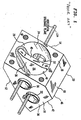
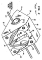
diverter valve housing 10 according to the teachings of the '150 patent comprising a body having aflat base 12, front andrear walls side walls base 12.Front wall 14 has aninlet port 22 formed therein which opens into achamber 24 formed within thehousing 10. Thechamber 24 has acurved drainage channel 26 at the bottom, and is subdivided by apartition 28. Therear wall 16 has a pair ofoutlet ports chamber 24 in thehousing 10. Thepartition 28 includes a tapered limb with walls between theports partition 28 forms thechamber 24 into afirst compartment 34, into which theport 22 opens, asecond compartment 36 into whichport 30 opens, and athird compartment 38 into whichport 32 opens (see FIG. 2). -
Side walls openings partition 28 hasedges openings edges recesses ports - Referring now also to FIG. 3, there is illustrated the
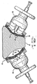
housing 10 of FIGS. 1 and 2 cross-sectioned through the center of theopenings diaphragms compressors Diaphragm 52 is closed against weir oredge 44, anddiaphragm 54 is removed from weir oredge 46. As a result, and as is conventionally understood, fluid flow fromport 22 toport 30 is prohibited, and flow is accommodated fromport 22 toport 32. - To insure against the trapping of fluids in the
housing 10, when the latter is horizontally disposed, as part of a diverter valve in a piping system, the '150 invention provides a horizontal drainage plane. The lowermost portions of theports openings edges drainage channel 26. There is offered, in thehousing 10, then, no pocket or recess in which a residual fluid can pool. In addition, theside walls rear walls walls housing 10 is greatly facilitated. The horizontal drainage plane of thehousing 10 is represented by theflow lines 120 shown in FIGS. 1 and 2. - As has been discovered, when a diverter valve of this type is installed in fluid process piping systems in a vertical disposition and when fluid flow is halted, the
housing 10 typically exhibits a sufficiently thorough drainage there through for many processes. However, there are piping systems which require the diverter valve exhibit an extraordinarily high amount of drainage as even a small amount of residual fluid remaining in the housing will be conducted out with a next flow of fluid, when the valve is operated again, thus contaminating the successive flow of fluid. This represents a significant problem in pharmaceutical and biotech process applications for example, where cleanliness and sterility are vital. - It is an object of the present invention to overcome this problem with a valve that exhibits this extraordinarily high amount of drainage whether it is installed in a horizontal or vertical position.
- A diverter valve housing including: a body including a base and a plurality of walls cooperatively forming a chamber; a partition within the chamber dividing the chamber into a plurality of compartments; a first port in a first of the walls and accessing a first of the compartments; and, second and third ports in a second of the walls and respectively accessing second and third ones of the compartments; wherein the partition further includes a surface which partially defines the first compartment and the surface is at least partially sloped towards the second wall.
-
- FIG. 1 is a perspective illustration of a prior art diverter valve housing;
- FIG. 2 is a perspective illustration of the housing of FIG. 1, the same taken from a different angle thereof;
- FIG. 3 is a combined cross-section and full line illustration of a diverter valve which incorporates the housing of FIGS. 1 and 2, the housing being shown in the cross-section, and the diaphragms and compressors therefor being shown substantially in full line depiction;
- FIG. 4 is a top, plan view of the housing of FIGS. 1 and 2 vertically disposed;
- FIG. 5 is a perspective illustration of a diverter valve housing according to a first embodiment of the present invention;
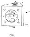
- FIG 6 is a perspective illustration of a diverter valve housing according to a second embodiment of the present invention; and,
- FIG. 7 is a perspective illustration of a diverter valve housing according to a third and preferred embodiment of the present invention.
-
- Referring now to FIG. 4, when the
housing 10 is vertically disposed within a process system such that theport 22 is disposed above theports partition 28 as has been described may partially inhibit drainage of thebody 10. Thepartition 28 typically includes a relatively large,flat surface 100 on one side of theweirs surface 100faces inlet port 22. - The
surface 100 in the embodiment illustrated in FIGS. 1 - 4 takes the form of a substantially triangular, horizontal surface when thehousing 10 has been installed in a vertical pipeline. Thus, with thehousing 10 installed in a vertical pipeline as has been described, thissurface 100 provides a shelf which, because of surface tension for example, may not sufficiently drain when the flow of fluid is halted. The drainage of fluid after the flow has halted is illustrated bypath 110 in FIG. 4. - According to the present invention, the
surface 100 is sloped towards theports surface 100, after fluid flow is halted, to more efficiently to drain. A slope as little as 1/2 of one degree (0.5°) has been found to be effective. The slope can be increased to any desired amount, providing thehorizontal drainage plane 120 as is illustrated in FIGS. 1 and 2 are maintained to allow for proper drainage in a horizontal disposition of thehousing 10 consistently with the teachings of the '150 patent. - Referring now to FIG. 5, there is illustrated a first embodiment of the housing 10' according to the present invention. Basically, the
surface 100 is made to taper or slope from thedivider 130 downwardly towards theedges surface 100 is made to include a raised ridge along thedivider 130 thereof. This forms twosurfaces 140, 150 which slope away from thedivider 130 and towards theports arrows 110 of FIG. 5 illustrate the direction of drainage after the fluid flow has been halted. The drainage can be seen to move away from thedivider 130 and towards both thecompartments - According to a preferred form of this first embodiment at least a portion of the
edges sloping surfaces 140, 150 meet theedges - Referring now to FIG. 6, there is illustrated a second embodiment of the present invention. Basically, in this second embodiment the
surface 100 is sloped towards thebase 12. Thearrow 110 of FIG. 6 again illustrates the vertical drainage pattern, wherein the drainage is directed towards thebase 12 and then towards theports edges sloping surface 100 meets theedges base 12, designated by thereference 105, are rounded or beveled to further reduce surface tension as fluid drains there over. - Referring now to FIG. 7, there is illustrated a preferred embodiment of the present invention. Basically, the
surface 100 in the embodiment of FIG. 7 is sloped in an opposite direction from that of FIG. 6, or away from thebase 12. As illustrated in FIGS. 1 - 7, thesurface 100 takes a substantially triangular shape. The embodiment of FIG. 6 drains fluid away from the apex 104 (FIG. 5) of and towards the base 102 (FIG. 5) of thetriangular surface 100, while the embodiment of FIG. 7 drains fluid away from the base 102 (FIG. 5) of and towards the apex 104 (FIG. 5) of thetriangular surface 100. Accordingly, the embodiment of FIG. 7 is preferable to that of FIG. 6 in some applications, as fluid drainage is directed towards the apex or narrower portion of the triangular cross-section of thesurface 100, thus reducing the surface area the draining fluid remains in contact with, thus further reducing the adverse effects of surface tension for example. - Again, according to a particularly preferred form of the preferred embodiment of FIG. 7, the portion of the
edges sloping surface 100 meets theedges base 12, designated in FIG. 7 byreference 115, are rounded or beveled to further reduce surface tension as fluid drains there over. - Although the invention has been described and pictured in a preferred form with a certain degree of particularity, it is understood that the present disclosure of the preferred form and alternative embodiments has been made only by way of example, and that numerous changes in the details of construction and combination and arrangement of parts may be made without departing from the spirit and scope of the invention.
Claims (20)
- A diverter valve housing comprising:a body including a base and a plurality of walls cooperatively forming a chamber;a partition within said chamber dividing said chamber into a plurality of compartments;a first port in a first of said walls and accessing a first of said compartments; and,second and third ports in a second of said walls and respectively accessing second and third ones of said compartments;wherein said partition further includes a surface which partially defines said first compartment and said surface is at least partially sloped towards said second wall.
- The housing of Claim 1, further comprising first and second openings respectively formed in a third and a fourth of said walls.
- The housing of Claim 2, wherein said partition further bisects said first and second openings.
- The housing of Claim 3, wherein at least a portion of said partition which bisects said first or second opening is beveled.
- The housing of Claim 3, wherein said first compartment opens to said first port and said first and second openings.
- The housing of Claim 5, wherein said second compartment opens to said first opening and said second port.
- The housing of Claim 6, wherein said third compartment opens to said second opening and said third port.
- The housing of Claim 7, wherein said chamber includes a curved drainage channel formed therein at a bottom thereof.
- The housing of Claim 8, wherein said walls and said partition have means cooperative with said channel for defining a horizontal drainage plane within said body.
- The housing of Claim 9, wherein said means for defining a horizontal drainage plane comprises lowermost portions of said ports, openings, and partition which are contiguous with, and flair into said channel.
- The housing of Claim 1, wherein said surface includes a ridge therein which projects towards said first port and slopes progressively towards said second wall as it approaches said third and forth walls.
- The housing of Claim 1, wherein said surface slopes towards said base.
- The housing of Claim 1, wherein said surface slopes away from said base.
- A housing suitable for use in a diverter valve, said housing comprising:a body including a substantially flat base and spaced-apart front, rear and side walls rising from said base, wherein said body forms a chamber having a curved drainage channel formed therein at the bottom thereof a chamber;a partition subdividing said chamber into compartments, wherein said walls and said partition includes means cooperative with said channel for defining a horizontal drainage plane within said body;an inlet port formed in said front wall;at least two outlet ports formed in said rear wall; and,at least one opening formed in each of said side walls;wherein said partition includes means for bisecting said openings and a surface adjacent to said inlet port and being at least partially sloped towards at least one of said outlet ports; and,said horizontal drainage plane defining means comprises lowermost portions of said ports, openings, and partition which are contiguous with, and flair into, said channel.
- The housing of Claim 14, wherein at least a portion of said partition which bisects said first or second opening includes a beveled edge.
- The housing of Claim 14, wherein said surface includes a ridge therein which projects towards said first port and slopes progressively towards at least one of said outlet ports.
- The housing of Claim 1, wherein said surface slopes towards said base.
- The housing of Claim 1, wherein said surface slopes away from said base.
- The housing of Claim 18, wherein at least a portion of said partition which bisects said first or second opening includes a beveled edge.
- A housing suitable for use in a diverter valve including:a body including a base and a plurality of walls cooperatively forming a chamber;a partition within said chamber dividing said chamber into a plurality of compartments;a first port in a first of said walls and accessing a first of said compartments; and,second and third ports in a second of said walls and respectively accessing second and third ones of said compartments; and,a curved drainage channel formed within said chamber at a bottom thereof adjacent to said base adapted for improving drainage of said housing when said housing is horizontally disposed;wherein said partition further includes a surface which partially defines said first compartment and said surface is at least partially sloped towards said second wall such as to improve drainage of said housing when said housing is vertically disposed.
Applications Claiming Priority (2)
| Application Number | Priority Date | Filing Date | Title |
|---|---|---|---|
| US533098 | 2000-03-23 | ||
| US09/533,098 US6237637B1 (en) | 2000-03-23 | 2000-03-23 | Housing for diverter valve |
Publications (3)
| Publication Number | Publication Date |
|---|---|
| EP1136736A2 true EP1136736A2 (en) | 2001-09-26 |
| EP1136736A3 EP1136736A3 (en) | 2003-02-12 |
| EP1136736B1 EP1136736B1 (en) | 2004-09-22 |
Family
ID=24124474
Family Applications (1)
| Application Number | Title | Priority Date | Filing Date |
|---|---|---|---|
| EP01850017A Expired - Lifetime EP1136736B1 (en) | 2000-03-23 | 2001-01-23 | Housing for a diverter valve |
Country Status (7)
| Country | Link |
|---|---|
| US (1) | US6237637B1 (en) |
| EP (1) | EP1136736B1 (en) |
| JP (1) | JP3375946B2 (en) |
| AR (1) | AR033355A1 (en) |
| AT (1) | ATE277315T1 (en) |
| BR (1) | BR0100681A (en) |
| DE (1) | DE60105678T2 (en) |
Families Citing this family (8)
| Publication number | Priority date | Publication date | Assignee | Title |
|---|---|---|---|---|
| US6672566B2 (en) * | 2001-11-13 | 2004-01-06 | Itt Manufacturing Enterprises, Inc. | Multi-use sterile access/GMP diaphragm valve housing |
| DE10156786B4 (en) * | 2001-11-19 | 2005-10-27 | Bark, Hannelore | Fitting body, in particular for a faucet, and valve assembly |
| AU2002953538A0 (en) * | 2002-12-23 | 2003-01-16 | Pickering, Graham | Clean line heated valve |
| DE202004007628U1 (en) * | 2004-05-12 | 2004-09-02 | Gemü Gebrüder Müller Apparatebau GmbH & Co. KG | valve body |
| DE202010003667U1 (en) * | 2010-03-16 | 2010-07-15 | Bürkert Werke GmbH | valve assembly |
| DE202010003665U1 (en) * | 2010-03-16 | 2010-07-15 | Bürkert Werke GmbH | valve manifold |
| DE202010003666U1 (en) * | 2010-03-16 | 2010-07-15 | Bürkert Werke GmbH | valve manifold |
| JP7375264B2 (en) * | 2019-06-28 | 2023-11-08 | トーステ株式会社 | Branch flow switching valve |
Citations (1)
| Publication number | Priority date | Publication date | Assignee | Title |
|---|---|---|---|---|
| US5427150A (en) | 1994-06-07 | 1995-06-27 | Itt Corporation | Housing for a diverter valve |
Family Cites Families (5)
| Publication number | Priority date | Publication date | Assignee | Title |
|---|---|---|---|---|
| JPS60151471A (en) * | 1984-01-13 | 1985-08-09 | Osame Kogyo Kk | Three-port three-position switching valve |
| DK0487703T4 (en) * | 1990-06-25 | 1999-12-20 | Alfa Laval Saunders Ltd | Valve for controlling connection to a branch passage |
| EP0619450A1 (en) * | 1993-04-09 | 1994-10-12 | The Boc Group, Inc. | Zero Dead-Leg Gas Cabinet |
| SE513253C2 (en) | 1997-09-09 | 2000-08-07 | Robovalve Ab | Diaphragm valve and valve housing for a diaphragm valve |
| CA2249815A1 (en) * | 1998-10-06 | 2000-04-06 | Kondandaraman Balasubramanian | Fluid diverter system |
-
2000
- 2000-03-23 US US09/533,098 patent/US6237637B1/en not_active Expired - Lifetime
-
2001
- 2001-01-23 DE DE60105678T patent/DE60105678T2/en not_active Expired - Lifetime
- 2001-01-23 AT AT01850017T patent/ATE277315T1/en not_active IP Right Cessation
- 2001-01-23 EP EP01850017A patent/EP1136736B1/en not_active Expired - Lifetime
- 2001-02-21 BR BR0100681-9A patent/BR0100681A/en active Search and Examination
- 2001-03-15 JP JP2001073331A patent/JP3375946B2/en not_active Expired - Fee Related
- 2001-03-20 AR ARP010101291A patent/AR033355A1/en active IP Right Grant
Patent Citations (1)
| Publication number | Priority date | Publication date | Assignee | Title |
|---|---|---|---|---|
| US5427150A (en) | 1994-06-07 | 1995-06-27 | Itt Corporation | Housing for a diverter valve |
Also Published As
| Publication number | Publication date |
|---|---|
| US6237637B1 (en) | 2001-05-29 |
| EP1136736A3 (en) | 2003-02-12 |
| ATE277315T1 (en) | 2004-10-15 |
| DE60105678T2 (en) | 2005-09-29 |
| JP2001280527A (en) | 2001-10-10 |
| JP3375946B2 (en) | 2003-02-10 |
| EP1136736B1 (en) | 2004-09-22 |
| BR0100681A (en) | 2001-11-06 |
| DE60105678D1 (en) | 2004-10-28 |
| AR033355A1 (en) | 2003-12-17 |
Similar Documents
| Publication | Publication Date | Title |
|---|---|---|
| US5427150A (en) | Housing for a diverter valve | |
| US6237637B1 (en) | Housing for diverter valve | |
| EP0618389A1 (en) | Diverter valve | |
| US3565107A (en) | Scupper valve | |
| US6068023A (en) | Valve for clearing air conditioning drain lines | |
| US20100301251A1 (en) | Plug valve with flow area equal to or greater than the flow area of the connected piping | |
| US9534368B1 (en) | Variable flow skimmer and shelf system | |
| US6024123A (en) | Fluid diverter system | |
| CA2417517C (en) | Diaphragm valve | |
| US6401756B1 (en) | Integral sterile access/ GMP diaphragm valve | |
| US20240011275A1 (en) | Crossflow setting devices and methods of use | |
| JPH09143968A (en) | Two-stage gate for sand discharge channel | |
| US6672566B2 (en) | Multi-use sterile access/GMP diaphragm valve housing | |
| JP2003329154A (en) | Three-way diaphragm valve | |
| RU2680293C1 (en) | Device of the valve for a refrigerant coolant | |
| EP3739135A1 (en) | Elongate silicone valve | |
| JP2004068328A (en) | Drain unit of bathroom | |
| JP2021021460A (en) | Float type steam trap | |
| JPS627744Y2 (en) | ||
| JP2002317487A (en) | Water diversion unit | |
| CA2432338C (en) | Even-flow septic tee arrangement | |
| JPH0247329Y2 (en) | ||
| JP3020897B2 (en) | Sewage rise | |
| JPS6043486B2 (en) | Reservoir sediment discharge device | |
| JP2004019747A (en) | Float type drain trap |
Legal Events
| Date | Code | Title | Description |
|---|---|---|---|
| PUAI | Public reference made under article 153(3) epc to a published international application that has entered the european phase |
Free format text: ORIGINAL CODE: 0009012 |
|
| AK | Designated contracting states |
Kind code of ref document: A2 Designated state(s): AT BE CH CY DE DK ES FI FR GB GR IE IT LI LU MC NL PT SE TR |
|
| AX | Request for extension of the european patent |
Free format text: AL;LT;LV;MK;RO;SI |
|
| PUAL | Search report despatched |
Free format text: ORIGINAL CODE: 0009013 |
|
| AK | Designated contracting states |
Designated state(s): AT BE CH CY DE DK ES FI FR GB GR IE IT LI LU MC NL PT SE TR |
|
| AX | Request for extension of the european patent |
Extension state: AL LT LV MK RO SI |
|
| 17P | Request for examination filed |
Effective date: 20030416 |
|
| 17Q | First examination report despatched |
Effective date: 20030815 |
|
| AKX | Designation fees paid |
Designated state(s): AT BE CH CY DE DK ES FI FR GB GR IE IT LI LU MC NL PT SE TR |
|
| GRAP | Despatch of communication of intention to grant a patent |
Free format text: ORIGINAL CODE: EPIDOSNIGR1 |
|
| GRAS | Grant fee paid |
Free format text: ORIGINAL CODE: EPIDOSNIGR3 |
|
| GRAA | (expected) grant |
Free format text: ORIGINAL CODE: 0009210 |
|
| AK | Designated contracting states |
Kind code of ref document: B1 Designated state(s): AT BE CH CY DE DK ES FI FR GB GR IE IT LI LU MC NL PT SE TR |
|
| PG25 | Lapsed in a contracting state [announced via postgrant information from national office to epo] |
Ref country code: IT Free format text: LAPSE BECAUSE OF FAILURE TO SUBMIT A TRANSLATION OF THE DESCRIPTION OR TO PAY THE FEE WITHIN THE PRESCRIBED TIME-LIMIT;WARNING: LAPSES OF ITALIAN PATENTS WITH EFFECTIVE DATE BEFORE 2007 MAY HAVE OCCURRED AT ANY TIME BEFORE 2007. THE CORRECT EFFECTIVE DATE MAY BE DIFFERENT FROM THE ONE RECORDED. Effective date: 20040922 Ref country code: FI Free format text: LAPSE BECAUSE OF FAILURE TO SUBMIT A TRANSLATION OF THE DESCRIPTION OR TO PAY THE FEE WITHIN THE PRESCRIBED TIME-LIMIT Effective date: 20040922 Ref country code: LI Free format text: LAPSE BECAUSE OF FAILURE TO SUBMIT A TRANSLATION OF THE DESCRIPTION OR TO PAY THE FEE WITHIN THE PRESCRIBED TIME-LIMIT Effective date: 20040922 Ref country code: CH Free format text: LAPSE BECAUSE OF FAILURE TO SUBMIT A TRANSLATION OF THE DESCRIPTION OR TO PAY THE FEE WITHIN THE PRESCRIBED TIME-LIMIT Effective date: 20040922 Ref country code: BE Free format text: LAPSE BECAUSE OF FAILURE TO SUBMIT A TRANSLATION OF THE DESCRIPTION OR TO PAY THE FEE WITHIN THE PRESCRIBED TIME-LIMIT Effective date: 20040922 Ref country code: AT Free format text: LAPSE BECAUSE OF FAILURE TO SUBMIT A TRANSLATION OF THE DESCRIPTION OR TO PAY THE FEE WITHIN THE PRESCRIBED TIME-LIMIT Effective date: 20040922 Ref country code: TR Free format text: LAPSE BECAUSE OF FAILURE TO SUBMIT A TRANSLATION OF THE DESCRIPTION OR TO PAY THE FEE WITHIN THE PRESCRIBED TIME-LIMIT Effective date: 20040922 Ref country code: NL Free format text: LAPSE BECAUSE OF FAILURE TO SUBMIT A TRANSLATION OF THE DESCRIPTION OR TO PAY THE FEE WITHIN THE PRESCRIBED TIME-LIMIT Effective date: 20040922 |
|
| REG | Reference to a national code |
Ref country code: GB Ref legal event code: FG4D |
|
| REG | Reference to a national code |
Ref country code: CH Ref legal event code: EP |
|
| REG | Reference to a national code |
Ref country code: IE Ref legal event code: FG4D |
|
| REF | Corresponds to: |
Ref document number: 60105678 Country of ref document: DE Date of ref document: 20041028 Kind code of ref document: P |
|
| PG25 | Lapsed in a contracting state [announced via postgrant information from national office to epo] |
Ref country code: SE Free format text: LAPSE BECAUSE OF FAILURE TO SUBMIT A TRANSLATION OF THE DESCRIPTION OR TO PAY THE FEE WITHIN THE PRESCRIBED TIME-LIMIT Effective date: 20041222 Ref country code: GR Free format text: LAPSE BECAUSE OF FAILURE TO SUBMIT A TRANSLATION OF THE DESCRIPTION OR TO PAY THE FEE WITHIN THE PRESCRIBED TIME-LIMIT Effective date: 20041222 Ref country code: DK Free format text: LAPSE BECAUSE OF FAILURE TO SUBMIT A TRANSLATION OF THE DESCRIPTION OR TO PAY THE FEE WITHIN THE PRESCRIBED TIME-LIMIT Effective date: 20041222 |
|
| PG25 | Lapsed in a contracting state [announced via postgrant information from national office to epo] |
Ref country code: ES Free format text: LAPSE BECAUSE OF FAILURE TO SUBMIT A TRANSLATION OF THE DESCRIPTION OR TO PAY THE FEE WITHIN THE PRESCRIBED TIME-LIMIT Effective date: 20050102 |
|
| PG25 | Lapsed in a contracting state [announced via postgrant information from national office to epo] |
Ref country code: LU Free format text: LAPSE BECAUSE OF NON-PAYMENT OF DUE FEES Effective date: 20050123 Ref country code: CY Free format text: LAPSE BECAUSE OF FAILURE TO SUBMIT A TRANSLATION OF THE DESCRIPTION OR TO PAY THE FEE WITHIN THE PRESCRIBED TIME-LIMIT Effective date: 20050123 |
|
| PG25 | Lapsed in a contracting state [announced via postgrant information from national office to epo] |
Ref country code: IE Free format text: LAPSE BECAUSE OF NON-PAYMENT OF DUE FEES Effective date: 20050124 |
|
| PG25 | Lapsed in a contracting state [announced via postgrant information from national office to epo] |
Ref country code: MC Free format text: LAPSE BECAUSE OF NON-PAYMENT OF DUE FEES Effective date: 20050131 |
|
| REG | Reference to a national code |
Ref country code: CH Ref legal event code: PL |
|
| NLV1 | Nl: lapsed or annulled due to failure to fulfill the requirements of art. 29p and 29m of the patents act | ||
| ET | Fr: translation filed | ||
| PLBE | No opposition filed within time limit |
Free format text: ORIGINAL CODE: 0009261 |
|
| STAA | Information on the status of an ep patent application or granted ep patent |
Free format text: STATUS: NO OPPOSITION FILED WITHIN TIME LIMIT |
|
| 26N | No opposition filed |
Effective date: 20050623 |
|
| REG | Reference to a national code |
Ref country code: IE Ref legal event code: MM4A |
|
| PG25 | Lapsed in a contracting state [announced via postgrant information from national office to epo] |
Ref country code: PT Free format text: LAPSE BECAUSE OF NON-PAYMENT OF DUE FEES Effective date: 20050222 |
|
| PGFP | Annual fee paid to national office [announced via postgrant information from national office to epo] |
Ref country code: FR Payment date: 20120130 Year of fee payment: 12 |
|
| PGFP | Annual fee paid to national office [announced via postgrant information from national office to epo] |
Ref country code: DE Payment date: 20120127 Year of fee payment: 12 |
|
| PGFP | Annual fee paid to national office [announced via postgrant information from national office to epo] |
Ref country code: GB Payment date: 20120126 Year of fee payment: 12 |
|
| GBPC | Gb: european patent ceased through non-payment of renewal fee |
Effective date: 20130123 |
|
| REG | Reference to a national code |
Ref country code: FR Ref legal event code: ST Effective date: 20130930 |
|
| PG25 | Lapsed in a contracting state [announced via postgrant information from national office to epo] |
Ref country code: DE Free format text: LAPSE BECAUSE OF NON-PAYMENT OF DUE FEES Effective date: 20130801 |
|
| REG | Reference to a national code |
Ref country code: DE Ref legal event code: R119 Ref document number: 60105678 Country of ref document: DE Effective date: 20130801 |
|
| PG25 | Lapsed in a contracting state [announced via postgrant information from national office to epo] |
Ref country code: FR Free format text: LAPSE BECAUSE OF NON-PAYMENT OF DUE FEES Effective date: 20130131 Ref country code: GB Free format text: LAPSE BECAUSE OF NON-PAYMENT OF DUE FEES Effective date: 20130123 |