EP1136716A1 - A method for detecting the occurence of a declutch - Google Patents
A method for detecting the occurence of a declutch Download PDFInfo
- Publication number
- EP1136716A1 EP1136716A1 EP01106758A EP01106758A EP1136716A1 EP 1136716 A1 EP1136716 A1 EP 1136716A1 EP 01106758 A EP01106758 A EP 01106758A EP 01106758 A EP01106758 A EP 01106758A EP 1136716 A1 EP1136716 A1 EP 1136716A1
- Authority
- EP
- European Patent Office
- Prior art keywords
- engine speed
- declutch
- transition
- open
- throttle
- Prior art date
- Legal status (The legal status is an assumption and is not a legal conclusion. Google has not performed a legal analysis and makes no representation as to the accuracy of the status listed.)
- Granted
Links
- 238000000034 method Methods 0.000 title claims abstract description 45
- 230000007704 transition Effects 0.000 claims abstract description 37
- 238000002485 combustion reaction Methods 0.000 claims abstract description 17
- 238000012544 monitoring process Methods 0.000 claims abstract description 15
- 239000000446 fuel Substances 0.000 claims description 26
- 230000001419 dependent effect Effects 0.000 claims description 14
- 230000010355 oscillation Effects 0.000 claims description 14
- 230000003247 decreasing effect Effects 0.000 claims description 7
- 238000001514 detection method Methods 0.000 abstract description 12
- 230000000994 depressogenic effect Effects 0.000 description 7
- 230000007423 decrease Effects 0.000 description 6
- 230000000881 depressing effect Effects 0.000 description 1
- 230000003071 parasitic effect Effects 0.000 description 1
Images

Classifications
-
- F—MECHANICAL ENGINEERING; LIGHTING; HEATING; WEAPONS; BLASTING
- F02—COMBUSTION ENGINES; HOT-GAS OR COMBUSTION-PRODUCT ENGINE PLANTS
- F02D—CONTROLLING COMBUSTION ENGINES
- F02D17/00—Controlling engines by cutting out individual cylinders; Rendering engines inoperative or idling
- F02D17/02—Cutting-out
-
- F—MECHANICAL ENGINEERING; LIGHTING; HEATING; WEAPONS; BLASTING
- F16—ENGINEERING ELEMENTS AND UNITS; GENERAL MEASURES FOR PRODUCING AND MAINTAINING EFFECTIVE FUNCTIONING OF MACHINES OR INSTALLATIONS; THERMAL INSULATION IN GENERAL
- F16D—COUPLINGS FOR TRANSMITTING ROTATION; CLUTCHES; BRAKES
- F16D48/00—External control of clutches
- F16D48/06—Control by electric or electronic means, e.g. of fluid pressure
-
- F—MECHANICAL ENGINEERING; LIGHTING; HEATING; WEAPONS; BLASTING
- F16—ENGINEERING ELEMENTS AND UNITS; GENERAL MEASURES FOR PRODUCING AND MAINTAINING EFFECTIVE FUNCTIONING OF MACHINES OR INSTALLATIONS; THERMAL INSULATION IN GENERAL
- F16D—COUPLINGS FOR TRANSMITTING ROTATION; CLUTCHES; BRAKES
- F16D2500/00—External control of clutches by electric or electronic means
- F16D2500/10—System to be controlled
- F16D2500/104—Clutch
- F16D2500/10406—Clutch position
- F16D2500/10412—Transmission line of a vehicle
-
- F—MECHANICAL ENGINEERING; LIGHTING; HEATING; WEAPONS; BLASTING
- F16—ENGINEERING ELEMENTS AND UNITS; GENERAL MEASURES FOR PRODUCING AND MAINTAINING EFFECTIVE FUNCTIONING OF MACHINES OR INSTALLATIONS; THERMAL INSULATION IN GENERAL
- F16D—COUPLINGS FOR TRANSMITTING ROTATION; CLUTCHES; BRAKES
- F16D2500/00—External control of clutches by electric or electronic means
- F16D2500/30—Signal inputs
- F16D2500/304—Signal inputs from the clutch
- F16D2500/30401—On-off signal indicating the engage or disengaged position of the clutch
-
- F—MECHANICAL ENGINEERING; LIGHTING; HEATING; WEAPONS; BLASTING
- F16—ENGINEERING ELEMENTS AND UNITS; GENERAL MEASURES FOR PRODUCING AND MAINTAINING EFFECTIVE FUNCTIONING OF MACHINES OR INSTALLATIONS; THERMAL INSULATION IN GENERAL
- F16D—COUPLINGS FOR TRANSMITTING ROTATION; CLUTCHES; BRAKES
- F16D2500/00—External control of clutches by electric or electronic means
- F16D2500/30—Signal inputs
- F16D2500/306—Signal inputs from the engine
- F16D2500/3061—Engine inlet air flow rate
-
- F—MECHANICAL ENGINEERING; LIGHTING; HEATING; WEAPONS; BLASTING
- F16—ENGINEERING ELEMENTS AND UNITS; GENERAL MEASURES FOR PRODUCING AND MAINTAINING EFFECTIVE FUNCTIONING OF MACHINES OR INSTALLATIONS; THERMAL INSULATION IN GENERAL
- F16D—COUPLINGS FOR TRANSMITTING ROTATION; CLUTCHES; BRAKES
- F16D2500/00—External control of clutches by electric or electronic means
- F16D2500/30—Signal inputs
- F16D2500/306—Signal inputs from the engine
- F16D2500/3067—Speed of the engine
-
- F—MECHANICAL ENGINEERING; LIGHTING; HEATING; WEAPONS; BLASTING
- F16—ENGINEERING ELEMENTS AND UNITS; GENERAL MEASURES FOR PRODUCING AND MAINTAINING EFFECTIVE FUNCTIONING OF MACHINES OR INSTALLATIONS; THERMAL INSULATION IN GENERAL
- F16D—COUPLINGS FOR TRANSMITTING ROTATION; CLUTCHES; BRAKES
- F16D2500/00—External control of clutches by electric or electronic means
- F16D2500/30—Signal inputs
- F16D2500/308—Signal inputs from the transmission
- F16D2500/30806—Engaged transmission ratio
-
- F—MECHANICAL ENGINEERING; LIGHTING; HEATING; WEAPONS; BLASTING
- F16—ENGINEERING ELEMENTS AND UNITS; GENERAL MEASURES FOR PRODUCING AND MAINTAINING EFFECTIVE FUNCTIONING OF MACHINES OR INSTALLATIONS; THERMAL INSULATION IN GENERAL
- F16D—COUPLINGS FOR TRANSMITTING ROTATION; CLUTCHES; BRAKES
- F16D2500/00—External control of clutches by electric or electronic means
- F16D2500/30—Signal inputs
- F16D2500/31—Signal inputs from the vehicle
- F16D2500/3108—Vehicle speed
-
- F—MECHANICAL ENGINEERING; LIGHTING; HEATING; WEAPONS; BLASTING
- F16—ENGINEERING ELEMENTS AND UNITS; GENERAL MEASURES FOR PRODUCING AND MAINTAINING EFFECTIVE FUNCTIONING OF MACHINES OR INSTALLATIONS; THERMAL INSULATION IN GENERAL
- F16D—COUPLINGS FOR TRANSMITTING ROTATION; CLUTCHES; BRAKES
- F16D2500/00—External control of clutches by electric or electronic means
- F16D2500/30—Signal inputs
- F16D2500/314—Signal inputs from the user
- F16D2500/31406—Signal inputs from the user input from pedals
- F16D2500/3144—Accelerator pedal position
-
- F—MECHANICAL ENGINEERING; LIGHTING; HEATING; WEAPONS; BLASTING
- F16—ENGINEERING ELEMENTS AND UNITS; GENERAL MEASURES FOR PRODUCING AND MAINTAINING EFFECTIVE FUNCTIONING OF MACHINES OR INSTALLATIONS; THERMAL INSULATION IN GENERAL
- F16D—COUPLINGS FOR TRANSMITTING ROTATION; CLUTCHES; BRAKES
- F16D2500/00—External control of clutches by electric or electronic means
- F16D2500/30—Signal inputs
- F16D2500/316—Other signal inputs not covered by the groups above
- F16D2500/3166—Detection of an elapsed period of time
-
- F—MECHANICAL ENGINEERING; LIGHTING; HEATING; WEAPONS; BLASTING
- F16—ENGINEERING ELEMENTS AND UNITS; GENERAL MEASURES FOR PRODUCING AND MAINTAINING EFFECTIVE FUNCTIONING OF MACHINES OR INSTALLATIONS; THERMAL INSULATION IN GENERAL
- F16D—COUPLINGS FOR TRANSMITTING ROTATION; CLUTCHES; BRAKES
- F16D2500/00—External control of clutches by electric or electronic means
- F16D2500/70—Details about the implementation of the control system
- F16D2500/706—Strategy of control
- F16D2500/70605—Adaptive correction; Modifying control system parameters, e.g. gains, constants, look-up tables
Definitions
- the present invention generally relates to a method for detecting the occurrence of a declutch of an internal combustion engine coupled to a clutch and a method for controlling an internal combustion engine.
- the object of the present invention is to propose a simple and efficient method for detecting the occurrence of a declutch. This object is achieved by a method as claimed in claim 1.
- a method in accordance with the invention concerns the detection of the occurrence of a declutch of an internal combustion engine coupled to a clutch and having a throttle valve for controlling intake air flow.
- the method comprises the steps of:
- the expected engine response is a decrease in engine speed.
- the clutch pedal is depressed, the engine speed has a tendency to increase.
- an increase in engine speed after a transition from open to closed throttle is a reliable criterion for detecting the occurrence of a declutch.
- the method can be easily implemented as it uses conventional parameters.
- transition from open to closed throttle means the transition from any open position of the throttle to the idle speed throttle position. In other words, if a transition to closed throttle position occurs, the throttle does not necessarily be fully closed.
- the occurrence of a declutch is only determined if the increase of the engine speed exceeds a predetermined delta engine speed threshold.
- the declutch is only detected, if the engine speed increases by a predetermined value above the engine speed at the transition from open to closed throttle. Hence the conclusion of the occurrence of a declutch on the basis of a parasitic increase in engine speed can be avoided.
- the drivetrain which is connected to the clutch, can be excited because of an abrupt engine torque change.
- these oscillations cause engine speed fluctuations, also in the form of gear dependent oscillations. Therefore, to prevent the erroneous detection of a declutch, the monitoring of the engine speed is preferably only started after a delay period following said transition from open to closed throttle.
- the monitoring of engine speed is preferably carried out during a limited time, called monitoring period, after a transition from open to closed throttle. This is to prevent the erroneous detection of a declutch when the throttle is closed driving downhill, thus causing an increase in engine speed over a certain time period depending on the gear.
- the delay period, the monitoring period, and/or the delta engine speed threshold are defined for each gear.
- the method is optimized in function of the gear, and permits an error free detection of a declutch.
- the engine speed is monitored during a gear dependent time window after the transition from open to closed throttle, starting after said delay period.
- the time window is defined so as to coincide temporally with the first valley of engine speed oscillations that would be caused by a let-off without a declutch. This permits to select a time interval during which, if no declutch is performed, the engine speed reaches a minimum. Hence, if an increase in engine speed is monitored during this time window, it can without any doubt be concluded to the occurrence of a declutch.
- the transition from open to closed throttle can easily be determined by a sensor associated to the throttle valve. However, this transition may also be determined on the basis of the position of the accelerator pedal. A let-off can thereby be used in the present method as an indication of a transition from open to closed throttle.
- a method for generating a signal indicating a declutch of an internal combustion engine coupled to a clutch, the engine having a throttle valve for controlling intake air flow.
- the method comprises the steps of:
- Such a method may be advantageously implemented on electronic engine controls where the indication of a declutch is needed as a condition in different procedures. It will be understood that the above described embodiments and preferences can be adapted to this method for generating a signal indicating a declutch.
- a method for controlling an internal combustion engine coupled to a clutch comprising a fuel supply and a throttle valve for controlling intake air flow. This method comprises the steps of:
- the fuel supply is preferably shut-off until the engine speed has decreased to a predetermined engine speed threshold value, e.g. the desired idle speed plus a calibratable offset, or until a transition from closed to open throttle has occurred, i.e. when the accelerator pedal is depressed.
- a predetermined engine speed threshold value e.g. the desired idle speed plus a calibratable offset
- the fuel supply is advantageously shut-off only if the speed of the vehicle driven by said internal combustion engine is higher than a predetermined vehicle speed threshold value.
- said fuel supply is preferably shut-off until the engine speed has decreased to a predetermined threshold value or until a transition from closed to open throttle has occurred or until the speed of the vehicle has decreased to a value below said predetermined vehicle speed threshold value.
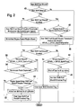
- Fig. 1 shows a flowchart of a preferred embodiment of a method of detecting a declutch respectively a gear shift according to the present invention. This method is used in a vehicle each time that the accelerator pedal is released, i.e. at each transition from open to closed throttle.
- a first (gear dependent) timer is decremented (shown at 14), the expiration of which sets the beginning of the detection time window.
- the first timer is preferably calibrated so as to expire at a moment at which the engine speed would decrease due to the above described drive train oscillations in the case of a let-off without declutch. Accordingly the monitoring of the engine speed is only started after a delay period following said transition from open to closed throttle.
- a second gear dependent timer is decremented at 16, the expiration of which sets the end of the detecting time window.
- the time window which is defined between the expiration of the timers is also gear dependent.
- the time window is defined so as to coincide temporally with the first valley of engine speed oscillations that would be caused by a let-off without a declutch. This permits to select a time interval during which, if no declutch is performed, the engine speed reaches a minimum.
- the gear shift detection method is enabled. Further conditions for the gear shift detection to be enabled may be set. For instance the engine speed should be higher than a minimum threshold speed value, below which a gear shift is not likely (see test at 22). Furthermore normal deceleration fuel shut off should not be enabled (test at 24) in order not to interfere with the corresponding algorithm. If one of these conditions is not met, the gear shift detecting method is disabled 26.
- the difference of the current engine speed and the engine speed at the moment of the pedal let-off is computed (28) and the so calculated difference is compared (30) to a gear dependent delta engine speed threshold value, which is indicative of the engine speed increase in case of a declutch.
- a gear dependent delta engine speed threshold value which is indicative of the engine speed increase in case of a declutch.
- the gear shift detected flag is cleared (34) and all the parameters of the method are reset.
- the current engine speed is constantly memorized to be used in the next loop of the algorithm as the engine speed at the moment of the transition from open to closed throttle 36.
- the first and second timers and the delta engine speed threshold value are initialized depending on the current gear 38.
- Fig.2 shows a flow chart of a method for controlling an internal combustion engine using the method of detection of a gear shift of Fig.1. If a gear shift is detected (at 40) and the fuel shut off is not already enabled, the fuel is shut off to all the cylinders 42 if the vehicle speed is higher than the above described vehicle speed threshold value 44. It follows that the fuel shut off is now enabled.
- the engine speed is then monitored 46 in order to detect the moment when the engine speed starts to decrease. Once the engine speed decreases, a fuel shut off disable threshold is set as the desired idle speed plus a calibratable offset 48. Once the engine speed has decreased to a value below this fuel shut off disable threshold (50), the fuel shut off is disabled again and fuel is supplied to all cylinders 52.
- fuel shut off is also disabled if the accelerator is depressed 54 or if the vehicle speed decreases below the vehicle speed threshold value 56.
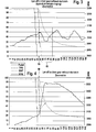
- Figures 3 and 4 illustrate the normal behavior of the engine speed in case of a transition from open to closed throttle (at 58) without declutch respectively followed by a declutch.
- the engine speed increases due to the large amount of air present in the manifold and the sudden decrease in the load on the engine.
- the resulting engine speed flare is represented in fig.4. If the let off is not followed by a declutch, the engine speed performs oscillations which dampen out with time. These oscillations are due to the drivetrain oscillations and accordingly the frequency and the amplitude of these oscillations are dependent on the gear. This case is illustrated in fig. 3.
- the drive train oscillations thus cause the engine speed to increase immediately after the transition from open to closed throttle. It follows that the monitoring of the engine speed immediately after the transition could lead to erroneous gear shift detection.
- the method according to the present invention proposes to preferably monitor the engine speed only during a gear dependent time window 60, which is defined so as to coincide temporally with the first valley of engine speed oscillations that would be caused by a let-off without a declutch (see fig. 3). If during this time window 60, the engine speed increases to a value above the gear dependent delta engine speed threshold value, one can without any doubt conclude to the occurrence of a declutch. Hence the fuel supply to the cylinders can be shut off and the speed flare shown in fig. 4 can be avoided.
Landscapes
- Engineering & Computer Science (AREA)
- General Engineering & Computer Science (AREA)
- Mechanical Engineering (AREA)
- Physics & Mathematics (AREA)
- Fluid Mechanics (AREA)
- Chemical & Material Sciences (AREA)
- Combustion & Propulsion (AREA)
- Electrical Control Of Air Or Fuel Supplied To Internal-Combustion Engine (AREA)
Abstract
- monitoring the engine speed after a transition from open to closed throttle; and
- concluding to the occurrence of a declutch if said engine speed increases.
Description
- The present invention generally relates to a method for detecting the occurrence of a declutch of an internal combustion engine coupled to a clutch and a method for controlling an internal combustion engine.
- A permanent concern of the automotive industry is to improve driveability, comfort and performance of vehicles. However, one problem that has been observed in modern engines is the occurrence of engine speed flares during gearshifts, even if the accelerator pedal had been entirely released before depressing the clutch pedal. The reason for this is that the load on the engine changes abruptly when the clutch pedal is depressed, while a lot of air is still available in the intake manifold. The amount of air trapped in the intake manifold is a given and cannot be modified. Hence, the only way to reduce or eliminate the engine speed flare is to shut-off fuel or spark until the amount of air in the manifold has reached a steady-state value. Shutting-off spark is however not conceivable, as fuel would flow through the combustion chamber into the exhaust. Moreover, fuel cannot be shut-off every time the accelerator pedal is released, i.e. every time the throttle is closed. It would indeed result in a sudden change in brake torque which leads to a bumpy behavior for normal let-offs without a declutch.
- One solution to reduce engine speed flares during gearshifts would be to shut-off fuel when the clutch pedal is depressed after a let-off. Unfortunately, until today there hasn't been proposed any efficient and reliable way to detect a declutch.
- The object of the present invention is to propose a simple and efficient method for detecting the occurrence of a declutch. This object is achieved by a method as claimed in claim 1.
- A method in accordance with the invention concerns the detection of the occurrence of a declutch of an internal combustion engine coupled to a clutch and having a throttle valve for controlling intake air flow. The method comprises the steps of:
- monitoring the engine speed after a transition from open to closed throttle; and
- concluding to the occurrence of a declutch if said engine speed increases.
- After a let-off, which causes a transition from open to closed throttle, the expected engine response is a decrease in engine speed. However, if the clutch pedal is depressed, the engine speed has a tendency to increase. Hence, an increase in engine speed after a transition from open to closed throttle is a reliable criterion for detecting the occurrence of a declutch. Moreover, the method can be easily implemented as it uses conventional parameters.
- It has to be noted, that the expression "transition from open to closed throttle" means the transition from any open position of the throttle to the idle speed throttle position. In other words, if a transition to closed throttle position occurs, the throttle does not necessarily be fully closed.
- In a preferred embodiment, the occurrence of a declutch is only determined if the increase of the engine speed exceeds a predetermined delta engine speed threshold. In other words, the declutch is only detected, if the engine speed increases by a predetermined value above the engine speed at the transition from open to closed throttle. Hence the conclusion of the occurrence of a declutch on the basis of a parasitic increase in engine speed can be avoided.
- As a matter of fact, on let-offs, respectively on transitions from open to closed throttle, the drivetrain, which is connected to the clutch, can be excited because of an abrupt engine torque change. This results in drivetrain oscillations, which are gear dependent and dampen out over time. Of course, these oscillations cause engine speed fluctuations, also in the form of gear dependent oscillations. Therefore, to prevent the erroneous detection of a declutch, the monitoring of the engine speed is preferably only started after a delay period following said transition from open to closed throttle.
- The monitoring of engine speed is preferably carried out during a limited time, called monitoring period, after a transition from open to closed throttle. This is to prevent the erroneous detection of a declutch when the throttle is closed driving downhill, thus causing an increase in engine speed over a certain time period depending on the gear.
- Advantageously, the delay period, the monitoring period, and/or the delta engine speed threshold are defined for each gear. Hence the method is optimized in function of the gear, and permits an error free detection of a declutch.
- It follows that the engine speed is monitored during a gear dependent time window after the transition from open to closed throttle, starting after said delay period. Preferably, the time window is defined so as to coincide temporally with the first valley of engine speed oscillations that would be caused by a let-off without a declutch. This permits to select a time interval during which, if no declutch is performed, the engine speed reaches a minimum. Hence, if an increase in engine speed is monitored during this time window, it can without any doubt be concluded to the occurrence of a declutch.
- The transition from open to closed throttle can easily be determined by a sensor associated to the throttle valve. However, this transition may also be determined on the basis of the position of the accelerator pedal. A let-off can thereby be used in the present method as an indication of a transition from open to closed throttle.
- According to another aspect of the invention, a method is proposed for generating a signal indicating a declutch of an internal combustion engine coupled to a clutch, the engine having a throttle valve for controlling intake air flow. The method comprises the steps of:
- monitoring the engine speed after reception of a signal indicating a transition from open to closed throttle; and
- generating a signal indicating a declutch if said engine speed increases.
- Such a method may be advantageously implemented on electronic engine controls where the indication of a declutch is needed as a condition in different procedures. It will be understood that the above described embodiments and preferences can be adapted to this method for generating a signal indicating a declutch.
- According to a further aspect of the present invention, a method is proposed for controlling an internal combustion engine coupled to a clutch, said combustion engine comprising a fuel supply and a throttle valve for controlling intake air flow. This method comprises the steps of:
- detecting a transition from open to closed throttle;
- detecting the occurrence of a declutch according to a method as set out above, and
- shutting-off said fuel supply if a declutch is detected.
- With this method for operating a combustion engine, the speed flares actually known in modern engines can be widely avoided. It will be appreciated, that the shutting-off of the fuel supply can be accompanied by a clearing of dashpot airflow offsets. It follows, that with the described method, engine speed flares can be reduced without having to compromise the normal amount of dashpot airflow offset. Up to now the dashpot airflow offset had always to be calibrated so as not to cause excessive engine speed flares on gear-shifts while still providing smooth let-off behavior.
- The fuel supply is preferably shut-off until the engine speed has decreased to a predetermined engine speed threshold value, e.g. the desired idle speed plus a calibratable offset, or until a transition from closed to open throttle has occurred, i.e. when the accelerator pedal is depressed.
- In order to avoid a bumpy behavior of the vehicle, the fuel supply is advantageously shut-off only if the speed of the vehicle driven by said internal combustion engine is higher than a predetermined vehicle speed threshold value. In this case said fuel supply is preferably shut-off until the engine speed has decreased to a predetermined threshold value or until a transition from closed to open throttle has occurred or until the speed of the vehicle has decreased to a value below said predetermined vehicle speed threshold value.
- The present invention will now be described, by way of example, with reference to the accompanying drawings, in which:
- Fig.1:
- shows a flow chart of a method for gear shift detection;
- Fig.2:
- shows a flow chart of a method for controlling an internal combustion engine;
- Fig.3:
- shows the graph of the engine speed in case of a transition from open to closed throttle without declutch.
- Fig.4:
- shows the graph of the normal engine speed in case of a transition from open to closed throttle followed by a declutch.
- Fig. 1 shows a flowchart of a preferred embodiment of a method of detecting a declutch respectively a gear shift according to the present invention. This method is used in a vehicle each time that the accelerator pedal is released, i.e. at each transition from open to closed throttle.
- As long as the comparison at 10 does not reveal, that the accelerator pedal is depressed again, and that the gear shift detection has not been disabled (test at 12), a first (gear dependent) timer is decremented (shown at 14), the expiration of which sets the beginning of the detection time window. The first timer is preferably calibrated so as to expire at a moment at which the engine speed would decrease due to the above described drive train oscillations in the case of a let-off without declutch. Accordingly the monitoring of the engine speed is only started after a delay period following said transition from open to closed throttle.
- A second gear dependent timer is decremented at 16, the expiration of which sets the end of the detecting time window. As the first and second timers are gear dependent, the time window which is defined between the expiration of the timers is also gear dependent. Preferably, the time window is defined so as to coincide temporally with the first valley of engine speed oscillations that would be caused by a let-off without a declutch. This permits to select a time interval during which, if no declutch is performed, the engine speed reaches a minimum.
- Only within the so defined time window, i.e. only after the first timer has expired (at 18) and while the second timer is still active (test at 20), the gear shift detection method is enabled. Further conditions for the gear shift detection to be enabled may be set. For instance the engine speed should be higher than a minimum threshold speed value, below which a gear shift is not likely (see test at 22). Furthermore normal deceleration fuel shut off should not be enabled (test at 24) in order not to interfere with the corresponding algorithm. If one of these conditions is not met, the gear shift detecting method is disabled 26.
- If however all the conditions are met, the difference of the current engine speed and the engine speed at the moment of the pedal let-off is computed (28) and the so calculated difference is compared (30) to a gear dependent delta engine speed threshold value, which is indicative of the engine speed increase in case of a declutch. In other words, if the engine speed increases so that the computed difference in engine speed exceeds this threshold value, there is concluded on the occurrence of a declutch and a respective flag is set at 32.
- If the accelerator is depressed (test at 10), the gear shift detected flag is cleared (34) and all the parameters of the method are reset. This means that e.g. the current engine speed is constantly memorized to be used in the next loop of the algorithm as the engine speed at the moment of the transition from open to
closed throttle 36. Furthermore the first and second timers and the delta engine speed threshold value are initialized depending on thecurrent gear 38. - Fig.2 shows a flow chart of a method for controlling an internal combustion engine using the method of detection of a gear shift of Fig.1. If a gear shift is detected (at 40) and the fuel shut off is not already enabled, the fuel is shut off to all the
cylinders 42 if the vehicle speed is higher than the above described vehiclespeed threshold value 44. It follows that the fuel shut off is now enabled. - The engine speed is then monitored 46 in order to detect the moment when the engine speed starts to decrease. Once the engine speed decreases, a fuel shut off disable threshold is set as the desired idle speed plus a calibratable offset 48. Once the engine speed has decreased to a value below this fuel shut off disable threshold (50), the fuel shut off is disabled again and fuel is supplied to all
cylinders 52. - It has to be noted that fuel shut off is also disabled if the accelerator is depressed 54 or if the vehicle speed decreases below the vehicle
speed threshold value 56. - Figures 3 and 4 illustrate the normal behavior of the engine speed in case of a transition from open to closed throttle (at 58) without declutch respectively followed by a declutch.
- If a declutch occurs and the fuel is not shut off, the engine speed increases due to the large amount of air present in the manifold and the sudden decrease in the load on the engine. The resulting engine speed flare is represented in fig.4. If the let off is not followed by a declutch, the engine speed performs oscillations which dampen out with time. These oscillations are due to the drivetrain oscillations and accordingly the frequency and the amplitude of these oscillations are dependent on the gear. This case is illustrated in fig. 3. The drive train oscillations thus cause the engine speed to increase immediately after the transition from open to closed throttle. It follows that the monitoring of the engine speed immediately after the transition could lead to erroneous gear shift detection.
- Accordingly the method according to the present invention proposes to preferably monitor the engine speed only during a gear
dependent time window 60, which is defined so as to coincide temporally with the first valley of engine speed oscillations that would be caused by a let-off without a declutch (see fig. 3). If during thistime window 60, the engine speed increases to a value above the gear dependent delta engine speed threshold value, one can without any doubt conclude to the occurrence of a declutch. Hence the fuel supply to the cylinders can be shut off and the speed flare shown in fig. 4 can be avoided.
Claims (13)
- A method for detecting the occurrence of a declutch of an internal combustion engine coupled to a clutch, said engine having a throttle valve for controlling intake air flow, characterized by the steps of:monitoring the engine speed after a transition from open to closed throttle; andconcluding to the occurrence of a declutch if said engine speed increases.
- The method according to claim 1, characterized in that there is concluded to the occurrence of a declutch if an increase of the engine speed exceeds a delta engine speed threshold.
- The method according to claim 1 or 2, characterized in that said monitoring is started after a delay period following said transition from open to closed throttle.
- The method according to claim 1, 2 or 3, characterized in that said monitoring of engine speed is carried out during a predetermined monitoring period.
- The method according to claims 2, 3 or 4, characterized in that said delay period, said monitoring period, and/or said delta engine speed threshold are gear dependent.
- The method according to claim 1, 2 or 3, characterized in that, said engine speed is monitored during a gear dependent time window after said transition from open to closed throttle.
- The method according to claim 6, wherein a transition from open to closed throttle causes gear-dependent engine speed oscillations, characterized in that said time window temporally coincides with a first valley of the engine speed oscillations that would be caused by a transition from open to closed throttle without a declutch.
- The method according to anyone of the preceding claims, wherein the throttle valve is controlled by an accelerator pedal, characterized in that said transition from open to closed throttle is determined on the basis of the position of said accelerator pedal.
- A method for generating a signal indicating a declutch of an internal combustion engine coupled to a clutch, said engine having a throttle valve for controlling intake air flow, characterized by the steps of:monitoring the engine speed after reception of a signal indicating a transition from open to closed throttle; andgenerating a signal indicating a declutch if said engine speed increases.
- A method for controlling an internal combustion engine coupled to a clutch, said combustion engine comprising a fuel supply and a throttle valve for controlling intake air flow, characterized by the steps of:detecting a transition from open to closed throttle;detecting the occurrence of a declutch according to a method as claimed in any one of claims 1 to 8, andshutting-off said fuel supply if a declutch is detected.
- Method according to claim 10, wherein said fuel supply is shut-off until the engine speed has decreased to a predetermined engine speed threshold value or until a transition from closed to open throttle has occurred.
- Method according to claim 10, wherein said fuel supply is shut-off only if a speed of a vehicle driven by said internal combustion engine is higher than a predetermined vehicle speed threshold value.
- Method according to claim 12, wherein said fuel supply is shut-off until the engine speed has decreased to a predetermined threshold value or until a transition from closed to open throttle has occurred or until the speed of the vehicle has decreased to a value below said predetermined vehicle speed threshold value.
Applications Claiming Priority (2)
| Application Number | Priority Date | Filing Date | Title |
|---|---|---|---|
| LU90556A LU90556B1 (en) | 2000-03-24 | 2000-03-24 | A method for detecting the occurrence of a declutch |
| LU90556 | 2000-03-24 |
Publications (2)
| Publication Number | Publication Date |
|---|---|
| EP1136716A1 true EP1136716A1 (en) | 2001-09-26 |
| EP1136716B1 EP1136716B1 (en) | 2008-05-14 |
Family
ID=19731883
Family Applications (1)
| Application Number | Title | Priority Date | Filing Date |
|---|---|---|---|
| EP01106758A Expired - Lifetime EP1136716B1 (en) | 2000-03-24 | 2001-03-17 | A method for detecting the occurence of a declutch |
Country Status (3)
| Country | Link |
|---|---|
| EP (1) | EP1136716B1 (en) |
| DE (1) | DE60133963D1 (en) |
| LU (1) | LU90556B1 (en) |
Citations (8)
| Publication number | Priority date | Publication date | Assignee | Title |
|---|---|---|---|---|
| US4632231A (en) * | 1983-06-30 | 1986-12-30 | Isuzu Motors Limited | Method of controlling the starting of a vehicle having automatic clutch |
| DE3809118A1 (en) * | 1987-03-26 | 1988-10-13 | Zahnradfabrik Friedrichshafen | Device for controlling an automatic motor vehicle clutch |
| EP0390423A1 (en) * | 1989-03-27 | 1990-10-03 | Diesel Kiki Co. Ltd. | Method for controlling an internal combustion engine for vehicle with automatic transmission system |
| EP0423799A2 (en) * | 1989-10-19 | 1991-04-24 | Toyota Jidosha Kabushiki Kaisha | Apparatus for controlling vehicle semi-automatic transmission, incorporating means for inhibiting automatic clutch from being fully released to avoid engine racing |
| FR2682649A1 (en) * | 1991-10-19 | 1993-04-23 | Fichtel & Sachs Ag | DEVICE FOR DETECTING THE POSITION OF THE START OF THE TRANSMISSION OF THE ROTATION TORQUE OF A CLUTCH OF A MOTOR VEHICLE. |
| EP0627336A2 (en) * | 1993-06-03 | 1994-12-07 | Aisin Aw Co., Ltd. | Shift control system for automatic transmissions |
| EP0697302A2 (en) * | 1994-08-19 | 1996-02-21 | Eaton Corporation | Downshift logic for semi-automatic mechanical transmission with manual clutch controller |
| DE19538308A1 (en) * | 1994-10-27 | 1996-05-02 | Volkswagen Ag | Method for controlling speed of IC engine |
-
2000
- 2000-03-24 LU LU90556A patent/LU90556B1/en active
-
2001
- 2001-03-17 DE DE60133963T patent/DE60133963D1/en not_active Expired - Lifetime
- 2001-03-17 EP EP01106758A patent/EP1136716B1/en not_active Expired - Lifetime
Patent Citations (8)
| Publication number | Priority date | Publication date | Assignee | Title |
|---|---|---|---|---|
| US4632231A (en) * | 1983-06-30 | 1986-12-30 | Isuzu Motors Limited | Method of controlling the starting of a vehicle having automatic clutch |
| DE3809118A1 (en) * | 1987-03-26 | 1988-10-13 | Zahnradfabrik Friedrichshafen | Device for controlling an automatic motor vehicle clutch |
| EP0390423A1 (en) * | 1989-03-27 | 1990-10-03 | Diesel Kiki Co. Ltd. | Method for controlling an internal combustion engine for vehicle with automatic transmission system |
| EP0423799A2 (en) * | 1989-10-19 | 1991-04-24 | Toyota Jidosha Kabushiki Kaisha | Apparatus for controlling vehicle semi-automatic transmission, incorporating means for inhibiting automatic clutch from being fully released to avoid engine racing |
| FR2682649A1 (en) * | 1991-10-19 | 1993-04-23 | Fichtel & Sachs Ag | DEVICE FOR DETECTING THE POSITION OF THE START OF THE TRANSMISSION OF THE ROTATION TORQUE OF A CLUTCH OF A MOTOR VEHICLE. |
| EP0627336A2 (en) * | 1993-06-03 | 1994-12-07 | Aisin Aw Co., Ltd. | Shift control system for automatic transmissions |
| EP0697302A2 (en) * | 1994-08-19 | 1996-02-21 | Eaton Corporation | Downshift logic for semi-automatic mechanical transmission with manual clutch controller |
| DE19538308A1 (en) * | 1994-10-27 | 1996-05-02 | Volkswagen Ag | Method for controlling speed of IC engine |
Also Published As
| Publication number | Publication date |
|---|---|
| LU90556B1 (en) | 2001-09-25 |
| EP1136716B1 (en) | 2008-05-14 |
| DE60133963D1 (en) | 2008-06-26 |
Similar Documents
| Publication | Publication Date | Title |
|---|---|---|
| JP4670912B2 (en) | Internal combustion engine control device | |
| EP2031223B1 (en) | Controller for internal combustion engine | |
| KR100292637B1 (en) | Fuel cut-off and fuel-supply recovery control system for internal combustion engine coupled to an automatic power transmission with a lock-up torque converter | |
| US7285073B2 (en) | Engine fuel supply control device | |
| US7032571B2 (en) | Internal combustion engine controller | |
| US7881846B2 (en) | Driveline clunk detection and control | |
| US8108112B2 (en) | Engine control during coasting events | |
| CN102052174A (en) | Engine control unit | |
| EP2071163A2 (en) | Control apparatus for engine and method of controlling engine | |
| JP2000073824A (en) | Electronic control unit for generating a fuel supply signal for an internal combustion engine | |
| US4788954A (en) | Method for controlling by-pass air flow on deceleration of internal combustion engine | |
| EP1136716A1 (en) | A method for detecting the occurence of a declutch | |
| US7415342B2 (en) | Fuel delivery control system | |
| JP4075589B2 (en) | Engine power transmission member abnormality determination device | |
| US20030168045A1 (en) | Method for the damping of mechanical vibrations in the drive train of an internal combustion engine | |
| JP2001355495A (en) | Fuel injection control device for in-vehicle internal combustion engine | |
| US6837826B2 (en) | Apparatus and a method for controlling an engine with an automatic transmission | |
| JP2000337495A (en) | Control device for automatic transmission | |
| JP4333017B2 (en) | Control device for internal combustion engine | |
| US11840229B1 (en) | Vehicle control apparatus | |
| JP3945612B2 (en) | Control device for engine with automatic transmission | |
| US4941556A (en) | Electronically-controlled fuel injection system for internal combustion engines | |
| JP3838855B2 (en) | Control device for internal combustion engine | |
| JPH0415538Y2 (en) | ||
| JP2998370B2 (en) | Fuel injection amount control device for internal combustion engine |
Legal Events
| Date | Code | Title | Description |
|---|---|---|---|
| PUAI | Public reference made under article 153(3) epc to a published international application that has entered the european phase |
Free format text: ORIGINAL CODE: 0009012 |
|
| AK | Designated contracting states |
Kind code of ref document: A1 Designated state(s): AT BE CH CY DE DK ES FI FR GB GR IE IT LI LU MC NL PT SE TR Kind code of ref document: A1 Designated state(s): DE FR IT |
|
| AX | Request for extension of the european patent |
Free format text: AL;LT;LV;MK;RO;SI |
|
| 17P | Request for examination filed |
Effective date: 20020202 |
|
| AKX | Designation fees paid |
Free format text: DE FR IT |
|
| 17Q | First examination report despatched |
Effective date: 20070727 |
|
| GRAP | Despatch of communication of intention to grant a patent |
Free format text: ORIGINAL CODE: EPIDOSNIGR1 |
|
| RIC1 | Information provided on ipc code assigned before grant |
Ipc: F16D 48/06 20060101AFI20071115BHEP Ipc: B60W 10/06 20060101ALN20071115BHEP Ipc: F02D 17/00 20060101ALI20071115BHEP Ipc: B60W 10/02 20060101ALN20071115BHEP |
|
| GRAS | Grant fee paid |
Free format text: ORIGINAL CODE: EPIDOSNIGR3 |
|
| GRAA | (expected) grant |
Free format text: ORIGINAL CODE: 0009210 |
|
| AK | Designated contracting states |
Kind code of ref document: B1 Designated state(s): DE FR IT |
|
| REF | Corresponds to: |
Ref document number: 60133963 Country of ref document: DE Date of ref document: 20080626 Kind code of ref document: P |
|
| PLBE | No opposition filed within time limit |
Free format text: ORIGINAL CODE: 0009261 |
|
| STAA | Information on the status of an ep patent application or granted ep patent |
Free format text: STATUS: NO OPPOSITION FILED WITHIN TIME LIMIT |
|
| 26N | No opposition filed |
Effective date: 20090217 |
|
| PGFP | Annual fee paid to national office [announced via postgrant information from national office to epo] |
Ref country code: FR Payment date: 20120319 Year of fee payment: 12 |
|
| PGFP | Annual fee paid to national office [announced via postgrant information from national office to epo] |
Ref country code: IT Payment date: 20120320 Year of fee payment: 12 |
|
| PGFP | Annual fee paid to national office [announced via postgrant information from national office to epo] |
Ref country code: DE Payment date: 20130327 Year of fee payment: 13 |
|
| REG | Reference to a national code |
Ref country code: FR Ref legal event code: ST Effective date: 20131129 |
|
| PG25 | Lapsed in a contracting state [announced via postgrant information from national office to epo] |
Ref country code: FR Free format text: LAPSE BECAUSE OF NON-PAYMENT OF DUE FEES Effective date: 20130402 |
|
| PG25 | Lapsed in a contracting state [announced via postgrant information from national office to epo] |
Ref country code: IT Free format text: LAPSE BECAUSE OF NON-PAYMENT OF DUE FEES Effective date: 20130317 |
|
| REG | Reference to a national code |
Ref country code: DE Ref legal event code: R119 Ref document number: 60133963 Country of ref document: DE |
|
| REG | Reference to a national code |
Ref country code: DE Ref legal event code: R119 Ref document number: 60133963 Country of ref document: DE Effective date: 20141001 |
|
| PG25 | Lapsed in a contracting state [announced via postgrant information from national office to epo] |
Ref country code: DE Free format text: LAPSE BECAUSE OF NON-PAYMENT OF DUE FEES Effective date: 20141001 |