EP1136456A2 - Method and apparatus for hot continuous fiber cooling with cooling gas recirculation - Google Patents
Method and apparatus for hot continuous fiber cooling with cooling gas recirculation Download PDFInfo
- Publication number
- EP1136456A2 EP1136456A2 EP01302595A EP01302595A EP1136456A2 EP 1136456 A2 EP1136456 A2 EP 1136456A2 EP 01302595 A EP01302595 A EP 01302595A EP 01302595 A EP01302595 A EP 01302595A EP 1136456 A2 EP1136456 A2 EP 1136456A2
- Authority
- EP
- European Patent Office
- Prior art keywords
- coolant gas
- mass flow
- passageway
- gas
- recirculation
- Prior art date
- Legal status (The legal status is an assumption and is not a legal conclusion. Google has not performed a legal analysis and makes no representation as to the accuracy of the status listed.)
- Granted
Links
Images

Classifications
-
- C—CHEMISTRY; METALLURGY
- C03—GLASS; MINERAL OR SLAG WOOL
- C03B—MANUFACTURE, SHAPING, OR SUPPLEMENTARY PROCESSES
- C03B37/00—Manufacture or treatment of flakes, fibres, or filaments from softened glass, minerals, or slags
- C03B37/01—Manufacture of glass fibres or filaments
- C03B37/02—Manufacture of glass fibres or filaments by drawing or extruding, e.g. direct drawing of molten glass from nozzles; Cooling fins therefor
- C03B37/025—Manufacture of glass fibres or filaments by drawing or extruding, e.g. direct drawing of molten glass from nozzles; Cooling fins therefor from reheated softened tubes, rods, fibres or filaments, e.g. drawing fibres from preforms
- C03B37/027—Fibres composed of different sorts of glass, e.g. glass optical fibres
- C03B37/02718—Thermal treatment of the fibre during the drawing process, e.g. cooling
-
- B—PERFORMING OPERATIONS; TRANSPORTING
- B01—PHYSICAL OR CHEMICAL PROCESSES OR APPARATUS IN GENERAL
- B01D—SEPARATION
- B01D2257/00—Components to be removed
- B01D2257/10—Single element gases other than halogens
- B01D2257/11—Noble gases
-
- C—CHEMISTRY; METALLURGY
- C03—GLASS; MINERAL OR SLAG WOOL
- C03B—MANUFACTURE, SHAPING, OR SUPPLEMENTARY PROCESSES
- C03B2205/00—Fibre drawing or extruding details
- C03B2205/57—Recovering, recycling or purifying the coolant, e.g. helium
Definitions
- the present Application relates to the cooling of hot continuous fibres using a coolant gas and has particular, but not exclusive, application to the cooling of Optical Fibres with helium. It provides both methods of cooling and apparatus for cooling.
- the Optical Fibre industry faces increasing pressure to reduce manufacturing costs while maintaining the highest standards of product quality.
- a major part of the operating cost of an Optical Fibre production facility is taken up by utilities and, in an effort to reduce one expensive utility, attention has been directed to the cost of helium used as a heat exchange medium between the Optical Fibre as it passes vertically down the centre of a draw tower and the externally cooled wall of the draw tower tube.
- helium used as a heat exchange medium between the Optical Fibre as it passes vertically down the centre of a draw tower and the externally cooled wall of the draw tower tube.
- all the helium supplied to the draw tower is allowed to escape to atmosphere through the open ends of the draw tower. It has been proposed in, for example, JP-A-60-046954, JP-A-4-240129 and EP-A-0094172 to recover and re-use the helium.
- the level of technology involved in optical fibre manufacture is very high.
- the fibres are manufactured in a batch process with strict controls on diameter to micron levels. This requires a sophisticated level of control from the draw furnace, to fibre diameter measurement, fibre cooling, coating application and draw speed control.
- the optimum is to produce the longest single length of fibre with consistent diameter in the fastest possible time while maintaining the desired light transmissibility parameters.
- a significant challenge is found in starting the draw process; obtaining the maximum draw speed and stable operation as fast as possible.
- recovering helium while maintaining stable operation presents a significant challenge. Changes affecting the efficiency of cooling in the draw tower can lead to off specification product, fibre breaks or coating problems which disrupt the fibre draw operation.
- JP-A-60-046954 discloses a heat exchanger for cooling an Optical Fibre by contact with a helium or a helium/inert coolant gas mixture during passage through a passageway in a heat exchanger.
- the coolant gas is recirculated with addition of fresh helium and, when using a gas mixture, inert gas.
- the flow of the recirculated gas after said addition is controlled, in unspecified manner, by a valve and monitored by a flow meter.
- the gas is cooled prior to entry into the passageway and/or the passageway is separately cooled.
- JP-A-4-240129 acknowledges as prior art thereto a process of JP-A-60-046954 in which an Optical Fibre is cooled by direct contact with a helium/nitrogen gas mixture as it is passed through a heat exchanger passageway countercurrent to the direction of gas flow.
- the gas is recirculated with addition of fresh helium and nitrogen.
- the recirculated gas after said addition is cooled prior to entry into the passageway and/or the passageway is separately cooled.
- a problem with the process of JP-A-60-046954 is the volume of helium required for cooling and the loss of helium gas and ingress of air at the ends of the heat exchanger passageway.
- JP-A-4-240129 seeks to overcome this problem by purifying the recycled helium to remove inter alia air which enters the heat exchanger passageway from the ends thereof. No details of flow control are provided.
- recycled helium gas is withdrawn from an upper outlet of the heat exchanger passageway and pumped to a helium gas purifier to remove air therefrom.
- Helium gas exiting the purifier is pumped to a gas mixer where make-up helium is added from a helium gas source.
- the resultant gas mixture is then supplied to a gas inlet at the bottom of the passageway.
- Figure 2 of JP-A-4-240129 differs from that of Figure 1 thereof in that the wall of the heat exchanger passageway is cooled and the made-up recirculated helium is cooled prior to return to the passageway.
- EP-A-0601601 discloses the recirculation of coolant gas from a heat exchanger having a passageway in which a hot continuous fibre is cooled with coolant gas and is particularly concerned with the cooling of Optical Fibres using helium.
- the flow of coolant gas into and out of the passageway is controlled based on one or more of the flow rate of, concentration of impurities in, and the pressure of recirculation coolant gas exiting the passageway.
- the means for controlling the flow may be "at least one flow resistance means, such as valves, orifices, sintered filters, narrow pipes having smaller diameters than the recovery conduit or packed beds” and that "adjustment of the flow resistance means can be made manually or automatically based on the flow rate, pressure and/or composition of the coolant gas" or "the flow resistance means can be preset or pre-adjusted based on experience and calculation or based on the flow rate, pressure and/or composition of a coolant gas".
- the only exemplification in EP-A-0601601 of monitored impurity in the coolant gas is that of oxygen concentration.
- EP-A-0094172 discloses recirculation of nitrogen or other inert gas to and from a drier in which a solvent is evaporated.
- the flow of exhaust inert gas from the drier is controlled in response to the flow rate from the drier outlet and the oxygen concentration in the drier.
- the recirculated inert gas is pumped to a condenser unit where solvent is removed and returned in part to the main body of the drier and in part to the ends of the drier as inert gas curtains. If the gas outlet pressure falls below a predetermined level, the gas flow to the pump is made up with recirculated gas from the condensation unit.
- the distribution and amount of recycled gas and provision of make-up inert gas is controlled in response to the flow rate through the gas outlet; the flow rate through the gas inlet; the solvent concentration in the drier; the oxygen concentration in the drier; and the pressure in the recirculated flow from the condensation unit.
- EP-A-0820963 discloses the recycle of helium from the fibre drawing step and at least one of the deposition and consolidation steps in an Optical Fibre manufacturing process.
- the used helium from these steps is partially purified to a low level purity and recycled to the fibre drawing process and/or further purified and recycled to at least one of the deposition, consolidation and fibre drawing steps.
- WO-A-9749960 discloses the recycle of helium from the consolidation step in an Optical Fibre manufacturing process.
- the used helium from this step is either purified to a high level purity for recycle to the consolidation step or partially purified to a low level for usage in fibre draw or other process steps and subsequent purification for recycle to the consolidation and, optionally, other process steps.
- Helium from the fibre draw or other process steps can be purified and recycled independently of the recycle of helium to the consolidation step.
- the present invention provides an improvement in cooling a hot continuous fibre by simultaneously passing the fibre through an open ended passageway of a heat exchanger located in an ambient oxygen-containing atmosphere; introducing into the passageway a coolant gas comprising recirculated purified coolant gas and fresh coolant gas; allowing a portion of used coolant gas to leave the passageway at said open ends to limit ingress of ambient atmosphere into the passageway; removing, purifying and recirculating to the passageway a portion of the used coolant gas; and monitoring the oxygen content of said removed portion.
- the improvement is that the mass flow of coolant gas introduced into the passageway can be controlled independently of its composition by providing for automatic interruption of the removal of used coolant gas for purification and recirculation when the oxygen content of the used coolant gas exceeds a predetermined maximum concentration until such time as the oxygen content falls below a predetermined minimum concentration.
- the method of the invention comprises simultaneously passing the fibre at constant speed through an open ended passageway of a heat exchanger located in an ambient moisture- and oxygen-containing atmosphere; introducing into the passageway a coolant gas containing at least 95% helium and comprising recirculated purified coolant gas and fresh helium; allowing a portion of used coolant gas to leave the passageway at said open ends to limit ingress of ambient atmosphere into the passageway; removing, drying and recirculating to the passageway a portion of the used coolant gas; and monitoring the oxygen content of said removed portion, wherein said removal of used coolant gas for purification and recirculation is automatically interrupted when the oxygen content of the used coolant gas exceeds a predetermined maximum concentration and recommenced when the oxygen content falls below a predetermined minimum concentration; and the mass flow of coolant gas introduced into the passageway is maintained independently of its composition.
- the method of the invention comprises simultaneously passing the fibre at constant speed through an open ended passageway of a heat exchanger located in an ambient moisture- and oxygen-containing atmosphere; introducing into the passageway a coolant gas containing at least 95% helium and comprising recirculated purified coolant gas and fresh helium; allowing a portion of used coolant gas to leave the passageway at said open ends to limit ingress of ambient atmosphere into the passageway; removing, drying and recirculating to the passageway a portion of the used coolant gas; and monitoring the oxygen content of said removed portion, wherein the mass flow of used coolant gas removed for purification and recirculation during normal operation is maintained at about90% of mass flow of the coolant gas introduced into the passageway but said removal of used coolant gas is automatically interrupted when the oxygen content thereof exceeds a predetermined maximum concentration and recommenced when the oxygen content falls below a predetermined minimum concentration; said removal of used coolant gas is by a vacuum pump drawing used coolant gas from more than one said passageway
- the invention also provides an apparatus for cooling a hot continuous fibre by the improved method of the invention.
- the apparatus comprises:
- the apparatus of the invention comprises:
- an improvement in a method of cooling a hot continuous fibre comprising simultaneously passing the fibre through an open ended passageway of a heat exchanger located in an ambient oxygen-containing atmosphere; introducing into the passageway a coolant gas comprising recirculated purified coolant gas and fresh coolant gas; allowing a portion of used coolant gas to leave the passageway at said open ends to limit ingress of ambient atmosphere into the passageway; removing, purifying and recirculating to the passageway a portion of the used coolant gas; and monitoring the oxygen content of said removed portion, the improvement consisting in automatically interrupting said removal of used coolant gas for purification and recirculation when the oxygen content of the used coolant gas exceeds a predetermined maximum concentration; recommencing said removal when the oxygen content falls below a predetermined minimum concentration; and controlling the mass flow of coolant gas introduced into the passageway independently of its composition.
- the present invention provides an apparatus for cooling a hot continuous fibre by the method of the first aspect, said apparatus comprising:
- the invention has particular, but not exclusive application to the cooling of an Optical Fibre using helium.
- maximum oxygen concentration permitted in the used gas typically will be about 2% and the minimum oxygen concentration typically about 1 %.
- the helium content of the coolant gas introduced into the passageway will be maintained within the range of 95% to 100%.
- the coolant gas is introduced into the passageway at about the mid-point thereof and the recirculation coolant gas removed at two locations each adjacent a respective open end of the passageway.
- the speed of the fibre and the mass flow of introduced coolant gas will be maintained constant during normal operation. Additionally or alternatively, the ratio of the mass flow of used coolant gas removed for purification and recirculation to the mass flow of the coolant gas introduced usually will be maintained constant at, for example, about 90:100 during normal operation. The proportion of used coolant gas removed for purification and recirculation during start up or following flow interruption can be gradually increased up to said mass flow .
- the purification of the recirculated coolant gas may be simply removal of moisture.
- the moisture removal conveniently is conducted by cooling the recirculated coolant gas to freeze out the water content thereof.
- Other contaminants, especially oxygen, can be removed by conventional techniques such as membrane separation or absorption.
- the oxygen concentration in the recirculated coolant gas is measured in a sample stream of used coolant gas removed from the passageway but it could be measured in the passageway itself.
- the analysed sample stream can be combined with the coolant gas removed for purification and recirculation to limit the loss of coolant gas.
- the used coolant gas is removed for purification and recirculation by a vacuum pump upstream of purification thereof.
- a mass flow controller can be located upstream of the pump to regulate the mass flow of the removed gas portion and a shut-off valve can be located between said mass flow controller and pump to interrupt and recommence recirculation in response to signals from the analyser.
- Optical Fibre production involves the parallel supply to a plurality of draw towers (heat exchanger) of coolant gas from a common source and accordingly it is desirable that a coolant gas recirculation system should be able to separately recover used coolant gas from each draw tower but combine the recovered streams prior to purification thereof.
- this can readily and efficiently be achieved by using the same vacuum pump to draw used coolant gas from the passageways of more than one heat exchanger with independent interruption and mass flow regulation of used coolant gas removal from each passageway in response to the oxygen content of the used coolant gas from the respective passageway.
- the pump is controlled to maintain a constant suction pressure and the respective mass flow controllers regulate mass flow from the respective passageways more rapidly than the pump can respond to corresponding changes in pressure levels.
- This difference in response times allows the mass flow controllers to operate with a defined pressure drop which can be optimised for the particular mass flow device to ensure that it operates within its optimum control range and hence maintain the control stability of the recovery system.
- the addition of fresh coolant gas to recirculated purified used coolant gas to provide the coolant gas introduced into the passageway conveniently is controlled by regulation of the pressure of said introduced coolant gas using respective pressure regulators on the fresh coolant gas and the recirculated coolant gas set to provide recirculated coolant gas in preference to fresh coolant gas.
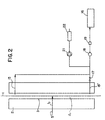
- an Optical Fibre 1 (see Figure 2) is drawn from a furnace (not shown) and cooled in a draw tower 2 prior to coating in conventional manner.
- the draw tower 2 is of essentially conventional structure consisting of a vertical right hollow cylindrical column wall 3 which is cooled externally with, for example, chilled water or a glycol/water system.
- the fibre 1 passes vertically down the centre of a passageway 4 defined by the wall 3.
- a coolant gas in line 5 is introduced into the passageway 4 through an inlet 6, preferably at a mid-point of the draw tower 2.
- the coolant gas in line 5 consists of a mixture of recirculated coolant gas provided via line 7 from a storage tank 26 and make-up helium provided via line 8 from a pure helium gas supply 9.
- Composition of the coolant gas in line 5 is by regulation of the pressure in that line using respective pressure regulators 10,11 set to control at different pressure levels such that the recirculated coolant gas in line 7 is used in preference to make-up helium in line 8. It will be apparent that when there is no recirculated coolant gas, the coolant gas 5 consists entirely of pure helium provided from the gas supply 9.
- the mass flow of coolant gas into the draw tower 2 is fixed and is measured by a mass flow meter 12.
- the pressure is regulated by a pressure regulator 13 upstream of the mass flow meter 12 and a shut-off valve 14 is provided downstream of the mass flow meter 12 to open and close the inlet 6 to the draw tower 2.
- the coolant gas acts as a heat exchange medium between the Optical Fibre 1 and the cylindrical wall 3 to cool the fibre as it passes through the passageway 4.
- all of the helium supplied through inlet 6 exits the passageway 4 through the ends thereof preventing ingress of the ambient atmosphere into the passageway 4 and contamination by coolant gas recirculation.
- the coolant gas in the draw tower 2 is maintained at a pressure slightly above atmospheric pressure to limit ingress of ambient atmosphere into the passageway 4 but the helium withdrawn through the outlets 15, 15' is nevertheless contaminated by the diffusion of components, particularly moisture and oxygen, from the ambient atmosphere.
- the outlets 15, 15' are manifolded to a vacuum pump 16 which provides the driving force for recirculation and is controlled to maintain a constant suction pressure of, for example, 500 mbara.
- the flow through the two outlets 15, 15' is balanced by a single valve 17 controlling flow through one of the outlets 15'.
- the flow of withdrawn gas is controlled by a mass flow controller 18 upstream of the vacuum pump 16 and a shut-off valve 19 is provided between the mass flow controller 18 and the vacuum pump 16.
- the pump 16 reacts slower to changes in pressure level than the mass flow controller 18 is able to increase of control the mass flow rate of withdrawn gas to the pump.
- the shut-off valve 19 In normal operation, the shut-off valve 19 is open allowing recirculation of the withdrawn gas and the mass flow controller 18 maintains the mass flow of the withdrawn gas at a constant proportion, for example 90%, of the mass of coolant gas supplied to the passageway 4 via line 5 through inlet 6. However, during the early stages of start-up of fibre production or during an interruption in gas recirculation (see below), the shut-off valve is closed preventing recirculation of withdrawn gas.
- the shut-off valve 19 On commencement of coolant gas recovery at a relevant stage during the start-up or on recommencement of recirculation following an interruption, the shut-off valve 19 is opened but the mass flow controller 18 controlled to ramp up the mass flow rate to the normal proportion over a predetermined time period and at a predetermined rate of mass flow increase.
- the fibre coating is temperature controlled and hence a step change in fibre temperature could cause the fibre coating to burn or break, or a section of off-specification fibre to be produced.
- the mass flow controller 18 is calibrated for a mixture of 2% air in helium. If the helium concentration varies from 95% to 100% the error in flow reading on the mass flow controller is ⁇ 2%. Since this is approximately the same as the manufacturer's guaranteed error for flow measurement, which is ⁇ 2% of full scale, it has no impact on the accuracy of the control system. The measurement error is further reduced because of the use of flow ratio control. There is a relatively small composition difference between the coolant gas in line 5 and the recirculated coolant gas in line 7. The difference between the actual coolant gas composition and the coolant gas composition used to calibrate the mass flow devices has the same effect on the "true flow" measurement error of both the mass flow measuring devices. Using the ratio of these measured flows as the control variable cancels out the effect of the measurement error.
- a sample of the withdrawn gas is removed upstream of the mass flow controller 18 and fed via pump 21 to analyser 22 which constantly monitors the oxygen content of the withdrawn gas.
- the oxygen content remains below a predetermined maximum concentration of, for example, 2%.
- a signal from the analyser 22 causes the shut-off valve 19 to close thereby isolating the vacuum pump 16 and interrupting flow of the withdrawn gas to the vacuum pump 16. This interruption limits the proportion of withdrawn gas to that supplying the analyser 22 and increases the flow of pure helium through line 8 and hence the helium content of the coolant gas supplied via line 5.
- the valve 19 remains closed until the oxygen concentration in the withdrawn gas detected by the analyser 22 falls below a predetermined concentration of, for example, 1%.
- valve 19 When the valve 19 is open, the proportion of gas passing through the analyser 22 can be added to the body of recirculated gas downstream of the vacuum pump 16. In this case, the set point of the mass flow controller 18 is adjusted to compensate for this addition to recirculated gas.
- the withdrawn gas passes from the vacuum pump 16 to a purifier 23 for the removal of moisture and, optionally, oxygen and/or other contaminants.
- moisture is removed by cooling the gas with, for example, liquid nitrogen to a temperature at which the moisture freezes out.
- Oxygen and other contaminants can be removed by conventional methods such as membrane separation or cryogenic absorption. However, in most Optical Fibre applications it will only be necessary to remove moisture from the recirculated coolant gas.
- Recirculation gas from the purifier is passed to a first storage vessel 24 and then via compressor 25 to a second storage vessel 26 from which the recirculated supply is withdrawn via line 7.
- draw towers 2, 2', 2" can be supplied via line 5 from a common source of coolant gas and can share a common recirculation circuit downstream of their respective shut-off valves 19, 19', 19".
- each draw tower 2, 2', 2" has independent coolant gas supply and withdrawal components as indicated in Figure 1 by the absence or presence of the corresponding superscript.
- the present invention constitutes a significant improvement over prior art methods of reusing helium as the draw tower coolant in Optical Fibre manufacture. As described below, the present method is simpler and provides more stable coolant flow control than that of EP-A-0601601.
- the time delay between the coolant gas entering the draw tower and being recovered and measured by the outlet mass flow device(s) and then controlled and the changing composition causes cyclic composition changes as the amount of coolant gas recovered cycles with changing gas composition.
- the influence of other draw towers on the inlet composition will possibly prevent the composition of the inlet and outlet coolant gas streams from ever achieving constant levels and may even affect the overall balance of control if the control system is not correctly tuned.
Landscapes
- Engineering & Computer Science (AREA)
- Chemical & Material Sciences (AREA)
- Manufacturing & Machinery (AREA)
- Life Sciences & Earth Sciences (AREA)
- General Life Sciences & Earth Sciences (AREA)
- Geochemistry & Mineralogy (AREA)
- Physics & Mathematics (AREA)
- Thermal Sciences (AREA)
- Materials Engineering (AREA)
- Organic Chemistry (AREA)
- Drying Of Gases (AREA)
- Manufacture, Treatment Of Glass Fibers (AREA)
- Inorganic Fibers (AREA)
Abstract
Description
Claims (29)
- A method of cooling a hot continuous fibre comprising simultaneously passing the fibre through an open ended passageway of a heat exchanger located in an ambient oxygen-containing atmosphere; introducing into the passageway a coolant gas comprising recirculated purified coolant gas and fresh coolant gas; allowing a portion of used coolant gas to leave the passageway at said open ends to limit ingress of ambient atmosphere into the passageway; removing, purifying and recirculating to the passageway a portion of the used coolant gas; and monitoring the oxygen content of said removed portion, characterised in that said removal of used coolant gas for purification and recirculation is automatically interrupted when the oxygen content of the used coolant gas exceeds a predetermined maximum concentration; said removal is recommenced when the oxygen content falls below a predetermined minimum concentration; and the mass flow of coolant gas introduced into the passageway is controlled independently of its composition.
- A method as claimed in Claim 1 in which the fibre is an Optical Fibre and the fresh coolant gas is helium.
- A method as claimed in Claim 1 or Claim 2 in which said maximum oxygen concentration is about 2% and the minimum oxygen concentration is about 1%.
- A method as claimed in Claim 2 or Claim 3 in which the helium content of the coolant gas introduced into the passageway is maintained within the range of 95% to 100%.
- A method as claimed in any one of the preceding claims in which the speed of the fibre and the mass flow of introduced coolant gas is maintained constant during normal operation.
- A method as claimed in any one of the preceding claims in which the coolant gas is introduced into the passageway at about the mid-point thereof and the used coolant gas removed for purification and recirculation is removed at two locations each adjacent a respective open end of the passageway.
- A method as claimed in any one of the preceding claims in which the ratio of the mass flow of used coolant gas removed for purification and recirculation to the mass flow of the coolant gas introduced is maintained constant during normal operation.
- A method as claimed in any one of the preceding claims in which the mass flow of used coolant gas removed for purification and recirculation is about 90% of mass flow of the coolant gas introduced.
- A method as claimed in any one of the preceding claims in which the proportion of used coolant gas removed for purification and recirculation during start up is gradually increased up to a predetermined ratio of the mass flow of used coolant gas removed for purification and recirculation to the mass flow of the coolant gas introduced.
- A method as claimed in any one of the preceding claims in which the proportion of used coolant gas removed for purification and recirculation following said interruption is gradually increased up to a predetermined ratio of the mass flow of used coolant gas removed for purification and recirculation to the mass flow of the coolant gas introduced.
- A method as claimed in any one of the preceding claim s in which said purification comprises removal of moisture.
- A method as claimed in Claim 11 in which the fibre is an Optical Fibre, the fresh coolant gas is helium, and moisture is removed by cooling the used coolant gas portion removed for recirculation to freeze out the water content thereof.
- A method as claimed in any one of the preceding claims in which said purification comprises the removal of oxygen.
- A method as claimed in any one of the preceding claims in which the oxygen concentration is measured in a sample stream of used coolant gas removed from the passageway.
- A method as claimed in Claim 14 in which, during normal operation, the sample stream is combined with the coolant gas removed for purification and recirculation.
- A method as claimed in any one of the preceding claims in which the used coolant gas removed for purification and recirculation is removed by a vacuum pump upstream of purification thereof; the mass flow of the removed gas portion is regulated by a mass flow controller upstream of said pump; and the flow is interrupted by a shut-off valve located between said mass flow controller and pump.
- A method as claimed in Claim 16 in which said pump draws used coolant gas from more than one said passageway with independent interruption and mass flow regulation of used coolant gas removal for purification and recirculation from each passageway in response to the oxygen content of the respective passageway.
- A method as claimed in Claim 17 in which said pump is controlled to maintain a constant suction pressure and the respective mass flow controllers regulate mass flow from the respective passageways more rapidly than the pump can respond to corresponding changes in pressure levels.
- A method as claimed in any one of the preceding claims in which addition of fresh coolant gas to recirculated purified used coolant gas to provide the coolant gas introduced into the passageway is controlled by regulation of the pressure of said introduced coolant gas using respective pressure regulators on the fresh coolant gas and the recirculated coolant gas set to provide recirculated coolant gas in preference to fresh coolant gas.
- An apparatus for cooling a hot continuous fibre comprising:a heat exchanger (2) for location in an ambient oxygen-containing atmosphere and having an open ended passageway (4) to receive the hot continuous fibre (1) for passage therethrough;inlet means (6) for introducing into the passageway a coolant gas comprising recirculated purified coolant gas (7) and fresh coolant gas (8) at a mass flow independent of said coolant gas composition.;outlet means (15,15') for removing a portion of used coolant gas from the passageway;purifying means (23) for purifying said removed portion of used coolant gas;pumping means (16, 25) for recirculating said removed coolant gas portion from said outlet means (15,15') to said inlet means (6) via said purifying means (23);oxygen analysis means (22) for monitoring the oxygen content of said removed coolant gas portion;recirculation flow control means (19) for interrupting said removal of used coolant gas; andsignal means for activating said recirculation flow control means (19) to automatically interrupt said removal of used coolant gas when the oxygen content measured by said oxygen analysis means (22) exceeds a predetermined maximum concentration and to recommence said removal when said measured oxygen content falls below a predetermined minimum concentration.
- A apparatus as claimed in Claim 20 in which the inlet means (6) introduces coolant gas into the passageway (4) at about the mid-point thereof and the outlet means (15,15') removes used coolant gas at two locations each adjacent a respective open end of the passageway (4).
- A apparatus as claimed in Claim 20 or Claim 21 further comprising mass flow control means (18) for maintaining constant during normal operation the ratio of the mass flow of used coolant gas removed by said outlet means (15,15') to the mass flow of the coolant gas introduced by said inlet means (6).
- A apparatus as claimed in Claim 22 in which the pumping means comprises a vacuum pump (16) upstream of said purifying means (23); said mass flow control means comprises a mass flow controller (18) upstream of said pump (16); and the recirculation control means comprises a shut-off valve (19) located between said mass flow controller (18) and said pump (16).
- A apparatus as claimed in Claim 23 in which said pump (16) is connected to the outlet means (15,15') of than one said passageway (4) with independent interruption (19,19',19") and independent mass flow regulation (18,18',18") of used coolant gas removal from each passageway (4) in response to the oxygen content of the respective passageway (4).
- A apparatus as claimed in Claim 24 in which said pump (16) is controlled to maintain a constant suction pressure and the respective mass flow controllers (18,18',18") regulate mass flow from the respective passageways (4) more rapidly than the pump (16) can respond to corresponding changes in pressure levels.
- A apparatus as claimed in any one of Claims 20 to 25 in which said purifying means (23) removes moisture from the used coolant gas.
- A apparatus as claimed in Claim 26 in which the purifying means (23) removes moisture by cooling the used coolant gas to freeze out the water content thereof.
- A apparatus as claimed in Claim 26 or Claim 27 in which said purifying means (23) also removes oxygen. form the used coolant gas.
- A apparatus as claimed in any one of Claims 20 to 28 in which the inlet means (6) comprises respective pressure regulators (11,10) on the fresh coolant gas and the recirculated coolant gas set to provide recirculated coolant gas in preference to fresh coolant gas.
Applications Claiming Priority (2)
| Application Number | Priority Date | Filing Date | Title |
|---|---|---|---|
| US535672 | 1983-09-26 | ||
| US09/535,672 US6345451B1 (en) | 2000-03-23 | 2000-03-23 | Method and apparatus for hot continuous fiber cooling with cooling gas recirculation |
Publications (3)
| Publication Number | Publication Date |
|---|---|
| EP1136456A2 true EP1136456A2 (en) | 2001-09-26 |
| EP1136456A3 EP1136456A3 (en) | 2002-05-02 |
| EP1136456B1 EP1136456B1 (en) | 2006-01-11 |
Family
ID=24135266
Family Applications (1)
| Application Number | Title | Priority Date | Filing Date |
|---|---|---|---|
| EP01302595A Revoked EP1136456B1 (en) | 2000-03-23 | 2001-03-21 | Method and apparatus for hot continuous fiber cooling with cooling gas recirculation |
Country Status (5)
| Country | Link |
|---|---|
| US (1) | US6345451B1 (en) |
| EP (1) | EP1136456B1 (en) |
| JP (1) | JP2001316126A (en) |
| AT (1) | ATE315540T1 (en) |
| DE (1) | DE60116566T2 (en) |
Cited By (2)
| Publication number | Priority date | Publication date | Assignee | Title |
|---|---|---|---|---|
| EP1394126A1 (en) * | 2002-08-28 | 2004-03-03 | The Boc Group, Inc. | Apparatus and method for recovery and recycle of coolant gas |
| CN102557426A (en) * | 2012-03-07 | 2012-07-11 | 中天科技光纤有限公司 | Optical fiber purifying device and optical fiber purifying method |
Families Citing this family (8)
| Publication number | Priority date | Publication date | Assignee | Title |
|---|---|---|---|---|
| FR2815399B1 (en) * | 2000-10-18 | 2003-01-03 | Air Liquide | PROCESS AND PLANT FOR PURIFICATION AND RECYCLING OF HELIUM AND THEIR APPLICATION TO THE MANUFACTURE OF OPTICAL FIBERS |
| JP4145673B2 (en) * | 2003-02-03 | 2008-09-03 | 独立行政法人科学技術振興機構 | Circulating liquid helium reliquefaction apparatus with pollutant discharge function, method for discharging pollutants from the apparatus, purifier and transfer tube used in the apparatus |
| KR100662189B1 (en) * | 2006-02-13 | 2006-12-27 | 두산중공업 주식회사 | Refrigerant gas recycling system for cryogenic chiller |
| US20090291199A1 (en) * | 2008-05-22 | 2009-11-26 | Paul Andrew Chludzinski | Apparatus and methods of control for coolant recycling |
| JP5323530B2 (en) * | 2009-02-23 | 2013-10-23 | 古河電気工業株式会社 | Optical fiber manufacturing method |
| US8444749B2 (en) * | 2009-06-10 | 2013-05-21 | L'air Liquide, Societe Anonyme Pour L'etude Et L'exploitation Des Procedes Georges Claude | Method and system for membrane-based gas recovery |
| US8230704B2 (en) | 2009-10-28 | 2012-07-31 | Corning Incorporated | Systems and methods for cooling optical fiber |
| JP2024078941A (en) * | 2022-11-30 | 2024-06-11 | 住友電気工業株式会社 | Optical fiber manufacturing apparatus and method |
Family Cites Families (7)
| Publication number | Priority date | Publication date | Assignee | Title |
|---|---|---|---|---|
| US4475293A (en) | 1982-04-28 | 1984-10-09 | The Boc Group, Inc. | Controlled inerting of chamber atmospheres |
| JPS6046954A (en) | 1983-08-26 | 1985-03-14 | Nippon Telegr & Teleph Corp <Ntt> | Device for drawing optical fiber |
| JPH04240129A (en) | 1991-01-18 | 1992-08-27 | Sumitomo Electric Ind Ltd | Method and apparatus for producing optical fiber |
| US5377491A (en) | 1992-12-11 | 1995-01-03 | Praxair Technology, Inc. | Coolant recovery process |
| JPH09142892A (en) * | 1995-11-28 | 1997-06-03 | Furukawa Electric Co Ltd:The | Coated optical fiber manufacturing apparatus and manufacturing method |
| CN1196789A (en) * | 1996-06-24 | 1998-10-21 | 康宁股份有限公司 | Helium recycling for optical fiber manufacturing |
| ID17537A (en) | 1996-07-26 | 1998-01-08 | Praxair Technology Inc | RETRIEVING HELIUM FOR OPTICAL FIBER MANUPACTURE |
-
2000
- 2000-03-23 US US09/535,672 patent/US6345451B1/en not_active Expired - Fee Related
-
2001
- 2001-03-21 AT AT01302595T patent/ATE315540T1/en not_active IP Right Cessation
- 2001-03-21 DE DE60116566T patent/DE60116566T2/en not_active Expired - Lifetime
- 2001-03-21 EP EP01302595A patent/EP1136456B1/en not_active Revoked
- 2001-03-22 JP JP2001083030A patent/JP2001316126A/en active Pending
Cited By (5)
| Publication number | Priority date | Publication date | Assignee | Title |
|---|---|---|---|---|
| EP1394126A1 (en) * | 2002-08-28 | 2004-03-03 | The Boc Group, Inc. | Apparatus and method for recovery and recycle of coolant gas |
| US6701728B1 (en) | 2002-08-28 | 2004-03-09 | The Boc Group, Inc. | Apparatus and method for recovery and recycle of optical fiber coolant gas |
| US7168256B2 (en) | 2002-08-28 | 2007-01-30 | The Boc Group, Inc. | Apparatus and method for recovery and recycle of optical fiber coolant gas |
| CN1318334C (en) * | 2002-08-28 | 2007-05-30 | 波克股份有限公司 | Apparatus and method for recovering and recirculating optical-fiber coolant gas |
| CN102557426A (en) * | 2012-03-07 | 2012-07-11 | 中天科技光纤有限公司 | Optical fiber purifying device and optical fiber purifying method |
Also Published As
| Publication number | Publication date |
|---|---|
| EP1136456A3 (en) | 2002-05-02 |
| DE60116566D1 (en) | 2006-04-06 |
| DE60116566T2 (en) | 2006-11-09 |
| EP1136456B1 (en) | 2006-01-11 |
| US6345451B1 (en) | 2002-02-12 |
| JP2001316126A (en) | 2001-11-13 |
| ATE315540T1 (en) | 2006-02-15 |
Similar Documents
| Publication | Publication Date | Title |
|---|---|---|
| US8444749B2 (en) | Method and system for membrane-based gas recovery | |
| JP7690561B2 (en) | Apparatus and membrane process for separating methane and carbon dioxide from a gas stream - Patents.com | |
| DE69921251T2 (en) | Cooling of optical fibers | |
| EP1136456B1 (en) | Method and apparatus for hot continuous fiber cooling with cooling gas recirculation | |
| EP0601601B2 (en) | Coolant recovery system | |
| EP0879389B1 (en) | Helium recycling for optical fiber manufacturing | |
| JP3703933B2 (en) | Permeation air separation method and apparatus for nitrogen production | |
| KR100981502B1 (en) | Apparatus and method for recovering and recycling fiber optic coolant gas | |
| JP2005114349A (en) | Method and system for optimizing argon recovery in air separation unit | |
| WO2010065880A2 (en) | Acetylene process gas purification methods and systems | |
| US4261719A (en) | Method of and apparatus for controlling rate of material air supply to air separation plant | |
| KR100844611B1 (en) | Process for recovering helium using eductor | |
| KR100226933B1 (en) | Oxygen purity control system of air separating apparatus | |
| JP2011184283A (en) | Equipment for producing nitrogen by membrane separation and method therefor | |
| JPH1163813A (en) | Method and device for recovering argon | |
| JPH04121574A (en) | Method and apparatus for recovering hydrogen through low temperature processing | |
| WO2000029798A2 (en) | Method and apparatus for regulating an atmosphere |
Legal Events
| Date | Code | Title | Description |
|---|---|---|---|
| PUAI | Public reference made under article 153(3) epc to a published international application that has entered the european phase |
Free format text: ORIGINAL CODE: 0009012 |
|
| AK | Designated contracting states |
Kind code of ref document: A2 Designated state(s): AT BE CH CY DE DK ES FI FR GB GR IE IT LI LU MC NL PT SE TR |
|
| AX | Request for extension of the european patent |
Free format text: AL;LT;LV;MK;RO;SI |
|
| PUAL | Search report despatched |
Free format text: ORIGINAL CODE: 0009013 |
|
| AK | Designated contracting states |
Kind code of ref document: A3 Designated state(s): AT BE CH CY DE DK ES FI FR GB GR IE IT LI LU MC NL PT SE TR |
|
| AX | Request for extension of the european patent |
Free format text: AL;LT;LV;MK;RO;SI |
|
| 17P | Request for examination filed |
Effective date: 20020717 |
|
| AKX | Designation fees paid |
Free format text: AT BE CH CY DE DK ES FI FR GB GR IE IT LI LU MC NL PT SE TR |
|
| GRAP | Despatch of communication of intention to grant a patent |
Free format text: ORIGINAL CODE: EPIDOSNIGR1 |
|
| GRAS | Grant fee paid |
Free format text: ORIGINAL CODE: EPIDOSNIGR3 |
|
| GRAA | (expected) grant |
Free format text: ORIGINAL CODE: 0009210 |
|
| AK | Designated contracting states |
Kind code of ref document: B1 Designated state(s): AT BE CH CY DE DK ES FI FR GB GR IE IT LI LU MC NL PT SE TR |
|
| PG25 | Lapsed in a contracting state [announced via postgrant information from national office to epo] |
Ref country code: IT Free format text: LAPSE BECAUSE OF FAILURE TO SUBMIT A TRANSLATION OF THE DESCRIPTION OR TO PAY THE FEE WITHIN THE PRESCRIBED TIME-LIMIT;WARNING: LAPSES OF ITALIAN PATENTS WITH EFFECTIVE DATE BEFORE 2007 MAY HAVE OCCURRED AT ANY TIME BEFORE 2007. THE CORRECT EFFECTIVE DATE MAY BE DIFFERENT FROM THE ONE RECORDED. Effective date: 20060111 Ref country code: NL Free format text: LAPSE BECAUSE OF FAILURE TO SUBMIT A TRANSLATION OF THE DESCRIPTION OR TO PAY THE FEE WITHIN THE PRESCRIBED TIME-LIMIT Effective date: 20060111 Ref country code: FI Free format text: LAPSE BECAUSE OF FAILURE TO SUBMIT A TRANSLATION OF THE DESCRIPTION OR TO PAY THE FEE WITHIN THE PRESCRIBED TIME-LIMIT Effective date: 20060111 Ref country code: CH Free format text: LAPSE BECAUSE OF FAILURE TO SUBMIT A TRANSLATION OF THE DESCRIPTION OR TO PAY THE FEE WITHIN THE PRESCRIBED TIME-LIMIT Effective date: 20060111 Ref country code: AT Free format text: LAPSE BECAUSE OF FAILURE TO SUBMIT A TRANSLATION OF THE DESCRIPTION OR TO PAY THE FEE WITHIN THE PRESCRIBED TIME-LIMIT Effective date: 20060111 Ref country code: LI Free format text: LAPSE BECAUSE OF FAILURE TO SUBMIT A TRANSLATION OF THE DESCRIPTION OR TO PAY THE FEE WITHIN THE PRESCRIBED TIME-LIMIT Effective date: 20060111 Ref country code: BE Free format text: LAPSE BECAUSE OF FAILURE TO SUBMIT A TRANSLATION OF THE DESCRIPTION OR TO PAY THE FEE WITHIN THE PRESCRIBED TIME-LIMIT Effective date: 20060111 |
|
| REG | Reference to a national code |
Ref country code: CH Ref legal event code: EP |
|
| REG | Reference to a national code |
Ref country code: IE Ref legal event code: FG4D |
|
| PG25 | Lapsed in a contracting state [announced via postgrant information from national office to epo] |
Ref country code: IE Free format text: LAPSE BECAUSE OF NON-PAYMENT OF DUE FEES Effective date: 20060321 |
|
| PG25 | Lapsed in a contracting state [announced via postgrant information from national office to epo] |
Ref country code: LU Free format text: LAPSE BECAUSE OF NON-PAYMENT OF DUE FEES Effective date: 20060331 Ref country code: MC Free format text: LAPSE BECAUSE OF NON-PAYMENT OF DUE FEES Effective date: 20060331 |
|
| REF | Corresponds to: |
Ref document number: 60116566 Country of ref document: DE Date of ref document: 20060406 Kind code of ref document: P |
|
| PG25 | Lapsed in a contracting state [announced via postgrant information from national office to epo] |
Ref country code: DK Free format text: LAPSE BECAUSE OF FAILURE TO SUBMIT A TRANSLATION OF THE DESCRIPTION OR TO PAY THE FEE WITHIN THE PRESCRIBED TIME-LIMIT Effective date: 20060411 Ref country code: SE Free format text: LAPSE BECAUSE OF FAILURE TO SUBMIT A TRANSLATION OF THE DESCRIPTION OR TO PAY THE FEE WITHIN THE PRESCRIBED TIME-LIMIT Effective date: 20060411 |
|
| PG25 | Lapsed in a contracting state [announced via postgrant information from national office to epo] |
Ref country code: ES Free format text: LAPSE BECAUSE OF FAILURE TO SUBMIT A TRANSLATION OF THE DESCRIPTION OR TO PAY THE FEE WITHIN THE PRESCRIBED TIME-LIMIT Effective date: 20060422 |
|
| PG25 | Lapsed in a contracting state [announced via postgrant information from national office to epo] |
Ref country code: PT Free format text: LAPSE BECAUSE OF FAILURE TO SUBMIT A TRANSLATION OF THE DESCRIPTION OR TO PAY THE FEE WITHIN THE PRESCRIBED TIME-LIMIT Effective date: 20060612 |
|
| NLV1 | Nl: lapsed or annulled due to failure to fulfill the requirements of art. 29p and 29m of the patents act | ||
| REG | Reference to a national code |
Ref country code: CH Ref legal event code: PL |
|
| ET | Fr: translation filed | ||
| PLBI | Opposition filed |
Free format text: ORIGINAL CODE: 0009260 |
|
| PLAX | Notice of opposition and request to file observation + time limit sent |
Free format text: ORIGINAL CODE: EPIDOSNOBS2 |
|
| 26 | Opposition filed |
Opponent name: L'AIR LIQUIDE, SOCIETE ANONYME POUR L Effective date: 20061011 |
|
| PLBB | Reply of patent proprietor to notice(s) of opposition received |
Free format text: ORIGINAL CODE: EPIDOSNOBS3 |
|
| PG25 | Lapsed in a contracting state [announced via postgrant information from national office to epo] |
Ref country code: GR Free format text: LAPSE BECAUSE OF FAILURE TO SUBMIT A TRANSLATION OF THE DESCRIPTION OR TO PAY THE FEE WITHIN THE PRESCRIBED TIME-LIMIT Effective date: 20060412 |
|
| PG25 | Lapsed in a contracting state [announced via postgrant information from national office to epo] |
Ref country code: TR Free format text: LAPSE BECAUSE OF FAILURE TO SUBMIT A TRANSLATION OF THE DESCRIPTION OR TO PAY THE FEE WITHIN THE PRESCRIBED TIME-LIMIT Effective date: 20060111 |
|
| PG25 | Lapsed in a contracting state [announced via postgrant information from national office to epo] |
Ref country code: CY Free format text: LAPSE BECAUSE OF FAILURE TO SUBMIT A TRANSLATION OF THE DESCRIPTION OR TO PAY THE FEE WITHIN THE PRESCRIBED TIME-LIMIT Effective date: 20060111 |
|
| PGFP | Annual fee paid to national office [announced via postgrant information from national office to epo] |
Ref country code: FR Payment date: 20110304 Year of fee payment: 11 |
|
| PGFP | Annual fee paid to national office [announced via postgrant information from national office to epo] |
Ref country code: DE Payment date: 20110331 Year of fee payment: 11 Ref country code: GB Payment date: 20110221 Year of fee payment: 11 |
|
| RDAF | Communication despatched that patent is revoked |
Free format text: ORIGINAL CODE: EPIDOSNREV1 |
|
| RDAG | Patent revoked |
Free format text: ORIGINAL CODE: 0009271 |
|
| STAA | Information on the status of an ep patent application or granted ep patent |
Free format text: STATUS: PATENT REVOKED |
|
| GBPC | Gb: european patent ceased through non-payment of renewal fee |
Effective date: 20120321 |
|
| 27W | Patent revoked |
Effective date: 20120728 |
|
| REG | Reference to a national code |
Ref country code: FR Ref legal event code: ST Effective date: 20121130 |
|
| REG | Reference to a national code |
Ref country code: DE Ref legal event code: R119 Ref document number: 60116566 Country of ref document: DE Effective date: 20121002 |
|
| PG25 | Lapsed in a contracting state [announced via postgrant information from national office to epo] |
Ref country code: GB Free format text: LAPSE BECAUSE OF NON-PAYMENT OF DUE FEES Effective date: 20120321 Ref country code: FR Free format text: LAPSE BECAUSE OF NON-PAYMENT OF DUE FEES Effective date: 20120402 |