EP1135248B1 - Method and apparatus for making integral rubber tractor tracks - Google Patents
Method and apparatus for making integral rubber tractor tracks Download PDFInfo
- Publication number
- EP1135248B1 EP1135248B1 EP99948463A EP99948463A EP1135248B1 EP 1135248 B1 EP1135248 B1 EP 1135248B1 EP 99948463 A EP99948463 A EP 99948463A EP 99948463 A EP99948463 A EP 99948463A EP 1135248 B1 EP1135248 B1 EP 1135248B1
- Authority
- EP
- European Patent Office
- Prior art keywords
- belt
- segments
- molding
- molding segments
- uncured
- Prior art date
- Legal status (The legal status is an assumption and is not a legal conclusion. Google has not performed a legal analysis and makes no representation as to the accuracy of the status listed.)
- Expired - Lifetime
Links
- 238000000034 method Methods 0.000 title claims abstract description 16
- 238000000465 moulding Methods 0.000 claims abstract description 127
- 230000000694 effects Effects 0.000 claims description 10
- 229910052782 aluminium Inorganic materials 0.000 claims description 4
- XAGFODPZIPBFFR-UHFFFAOYSA-N aluminium Chemical compound [Al] XAGFODPZIPBFFR-UHFFFAOYSA-N 0.000 claims description 4
- 238000010438 heat treatment Methods 0.000 claims description 4
- 238000004519 manufacturing process Methods 0.000 claims description 2
- 238000001816 cooling Methods 0.000 claims 2
- 238000003825 pressing Methods 0.000 claims 1
- 230000000452 restraining effect Effects 0.000 claims 1
- 239000012530 fluid Substances 0.000 description 8
- 238000010276 construction Methods 0.000 description 4
- XLYOFNOQVPJJNP-UHFFFAOYSA-N water Substances O XLYOFNOQVPJJNP-UHFFFAOYSA-N 0.000 description 4
- 229910052751 metal Inorganic materials 0.000 description 3
- 239000002184 metal Substances 0.000 description 3
- 229910000831 Steel Inorganic materials 0.000 description 2
- 238000003490 calendering Methods 0.000 description 2
- 238000005188 flotation Methods 0.000 description 2
- 239000010959 steel Substances 0.000 description 2
- 239000000853 adhesive Substances 0.000 description 1
- 230000001070 adhesive effect Effects 0.000 description 1
- 238000013459 approach Methods 0.000 description 1
- 238000005056 compaction Methods 0.000 description 1
- 230000000295 complement effect Effects 0.000 description 1
- 230000008602 contraction Effects 0.000 description 1
- 238000012423 maintenance Methods 0.000 description 1
Images


Classifications
-
- B—PERFORMING OPERATIONS; TRANSPORTING
- B29—WORKING OF PLASTICS; WORKING OF SUBSTANCES IN A PLASTIC STATE IN GENERAL
- B29D—PRODUCING PARTICULAR ARTICLES FROM PLASTICS OR FROM SUBSTANCES IN A PLASTIC STATE
- B29D29/00—Producing belts or bands
- B29D29/08—Toothed driving belts
- B29D29/085—Double-toothed driving belts
-
- B—PERFORMING OPERATIONS; TRANSPORTING
- B29—WORKING OF PLASTICS; WORKING OF SUBSTANCES IN A PLASTIC STATE IN GENERAL
- B29C—SHAPING OR JOINING OF PLASTICS; SHAPING OF MATERIAL IN A PLASTIC STATE, NOT OTHERWISE PROVIDED FOR; AFTER-TREATMENT OF THE SHAPED PRODUCTS, e.g. REPAIRING
- B29C43/00—Compression moulding, i.e. applying external pressure to flow the moulding material; Apparatus therefor
-
- B—PERFORMING OPERATIONS; TRANSPORTING
- B29—WORKING OF PLASTICS; WORKING OF SUBSTANCES IN A PLASTIC STATE IN GENERAL
- B29K—INDEXING SCHEME ASSOCIATED WITH SUBCLASSES B29B, B29C OR B29D, RELATING TO MOULDING MATERIALS OR TO MATERIALS FOR MOULDS, REINFORCEMENTS, FILLERS OR PREFORMED PARTS, e.g. INSERTS
- B29K2021/00—Use of unspecified rubbers as moulding material
-
- B—PERFORMING OPERATIONS; TRANSPORTING
- B29—WORKING OF PLASTICS; WORKING OF SUBSTANCES IN A PLASTIC STATE IN GENERAL
- B29K—INDEXING SCHEME ASSOCIATED WITH SUBCLASSES B29B, B29C OR B29D, RELATING TO MOULDING MATERIALS OR TO MATERIALS FOR MOULDS, REINFORCEMENTS, FILLERS OR PREFORMED PARTS, e.g. INSERTS
- B29K2105/00—Condition, form or state of moulded material or of the material to be shaped
- B29K2105/06—Condition, form or state of moulded material or of the material to be shaped containing reinforcements, fillers or inserts
- B29K2105/08—Condition, form or state of moulded material or of the material to be shaped containing reinforcements, fillers or inserts of continuous length, e.g. cords, rovings, mats, fabrics, strands or yarns
- B29K2105/10—Cords, strands or rovings, e.g. oriented cords, strands or rovings
- B29K2105/101—Oriented
Definitions
- the present invention relates generally to the molding of vehicle supporting elements formed of rubber and more particularly, to a system for molding rubber tractor tracks in an endless configuration.
- Rubber tractor tracks are in many cases being substituted for conventional metal tractor tracks. Rubber tractor tracks offer better maneuverability, better ride quality in rough fields, better flotation in wet fields, improved side hill stability, excellent traction, low maintenance and versatility compared to steel tractor tracks. Additionally, rubber tracks are replacing conventional rubber tires on tractor and other agricultural vehicles such as combines, trenchers, snow removers, spreaders, sprayers, wagons and carts, since rubber tracks are more friendly to agricultural fields, offer better flotation and less compaction than rubber tires, resulting in better crop yield. The use of rubber tractor tracks permits farmers to get out into the fields earlier in the planting season and plant more crops as compared to rubber tire-equipped agricultural vehicles.
- Rubber tractor tracks are defined by an endless rubber belt reinforced with continuous flexible steel cables bonded into the rubber.
- a complete rubber tractor track is molded flat in quarter sections which are sequentially then bonded together during the curing process.
- the joint between the bonded-together sections tend to break in use.
- the joint between the bonded-together ends is of a different cross-sectional dimension than the cross-sectional dimension of the major portion of the track length. Accordingly, during movement of the track-supported vehicle, the vehicle is subject to severe vibrations. Such vibrations are not only harmful to the vehicle, but also to pavement over which the vehicle is moved. Additionally, such vibration is annoying to the vehicle operator.
- the most relevant prior art track molding apparatus is descried in USA-4207052.
- That apparatus has a molding press having a plurality of horizontal movable outer molding segments formed with tread defining recesses on their inner portion.
- the apparatus further comprises a plurality of inner molding segments, means to urge these segments outwardly, a belt handler for positioning an uncured belt outwardly of the inner molding segments.
- Another method involves building a complete track using a drum. Uncured or cured lugs are first manually clamped within pockets formed in drum. Next, uncured rubber, calendered cord and wire cable are wrapped around the outside of the drum. Preformed uncured treads are then stitched onto the uncured rubber. The drum is then disposed within an autoclave to cure the rubber and the parts attached thereto. The drum is then collapsed to remove the completed track. Since only low pressure can be applied the cured rubber is of a low density with resulting low strength. Also, the track lugs and treads are not generally integrally bonded to the rubber and are displaced during use.
- the method and apparatus for molding rubber tractor tracks of the present invention effects complete molding of an entire rubber track in an endless configuration of uniform thickness so as to eliminate any discontinuity in cross-section along the length of the rubber track.
- a rubber track embodying the present invention eliminates the vibration created by the bonded-together sections of a conventional rubber tractor track during vehicle movement.
- a rubber tractor track embodying the present invention is not subject to breakage as in the case of a conventional rubber tractor track formed of bonded-together sections.
- a rubber tractor track made in accordance with the present invention is completely integral with respect to the lugs and treads whereby the lugs and treads will not become separated from the track.
- Another advantage of the method of molding rubber tire tracks embodying the present invention is the reduction in manufacturing time and cost afforded by such method, as compared to the prior art methods described above.
- This advantage is broadly achieved by molding an initially uncured belt, securing drive lugs to the inner periphery of the uncured belt, inserting the uncured belt into a molding press, heating the molding press to mold treads on the outer portion of the belt while bonding the drive lugs to the inner portion of the belt, and then removing the cured belt and its drive lugs from the molding press.
- the apparatus of the present invention includes a molding press having a plurality of horizontally movable outer molding segments formed with tread-defining recesses on their inner portions, a segment loader having a plurality of horizontally movable inner molding segments, each molding segment having a drive lug cavity that initially removably holds a drive lug, a belt handler for positioning an uncured belt within the confines of the inner molding segments of the segment loader, a power-operated segment loader to urge the inner molding segments outwardly to secure the drive lugs against the inner periphery of the uncured belts and a segment handler for moving the inner molding segments and uncured belt into the space encompassed by the outer molding segments of the molding press to effect curing of the belt between the inner and outer molding segments while forming the treads on the outer surface of the belt and bonding the drive lugs onto the inner portion of the belt, with the segment handler thereafter withdrawing the inner molding segments and cured belt from the molding press.
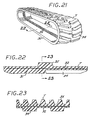
- a completed a rubber track T made in accordance with the method and apparatus of the present invention.
- Such track T comprises an endless band 30 formed of rubber 31 and calendered cord and wire cable 32 embedded in band 30.
- Such track T is adapted to be positioned upon the wheels and rollers of a motorized vehicle (not shown), such as a tractor or the like to support such vehicle for movement along a desired surface, such as an agricultural field.
- the exterior surface of band 30 is formed with integral treads 34.
- the mid portion of the interior periphery of band 30 is formed with a plurality of drive lugs 35 which engage complimentary sprockets (not shown) on the wheels or rollers of the vehicle which is supported by track T.
- Track T of Figs. 21, 22 and 23 is formed by the apparatus shown in Figs. 1 through 20.
- a molding press gantry MG and a segment gantry SG both horizontally movable along the floor C.
- the major components of the track forming apparatus embodying the present invention includes a molding press M (Figs. 4 and 8-10) having a lower platen, generally designated 40, and a mold top member, generally designated 42, a pair of belt handlers BH-1 and BH-2, a segment handler SH (Fig. 6), and a segment loader SL ( Figs. 6 and 7).
- the molding press gantry MG effects vertical and horizontal movement of the molding press top member 42 relative to the molding press lower platen 40.
- the segment gantry SG effects vertical and horizontal movement of the segment handler SH relative to the molding press M and segment loader SL.
- Belt handler BH-1 is swung from a first position over a conveyor belt 44 to a second position aligned with segment loader SL so as to move uncured belts 45 from the conveyor belt into segment loader SL.
- Belt handler BH-2 is swung from a position over segment loader SL to a position over the conveyor belt 44 to transfer a cured track T onto the conveyor belt.
- molding press gantry MG is of conventional construction having crossbars which support four, vertical, like, equidistantly spaced electric motor driven-lifting screw rods 46.
- Another electric motor 47 drives rollers 48 which ride on rails 49 secured to columns 50.
- Segment gantry SG is similar in construction to molding press gantry MG and includes four, vertical, like, electric motor-driven lifting screw rods 51.
- Electric motor 52 drive rollers 53 that ride on rails 49.
- lower platen 40 is disposed within a depression formed in floor C and includes a base 54 from the center of which extends a guide post 56.
- a plurality of like, outer hydraulic cylinder and plunger closing units 58 extend upwardly from the sides of the lower platen 40.
- the inner portion of lower platen base 54 supports inner hydraulic cylinder and plunger units 60.
- the molding press top 42 is lifted onto and off of the lower platen by the vertically reciprocal lifting screw rods 46 of gantry MG (Fig. 9).
- the upper portion of the plungers 61 of the inner cylinder plunger units 60 are affixed to a guide member generally designated 62, the upper portion of which is formed with a recess 63 selectively locked to the upper portion of press top 42 by horizontally movable U-shaped locking plates 64 operated by horizontally disposed fluid actuated cylinder and plunger units 66.
- a second plurality of horizontally extending fluid actuated cylinder and plunger units 71 are secured to the lower platen 40 to effect horizontal movement of a plurality of molding press segments 72 which are secured to heat-transfer hollow cones 73 relative to the floor of the lower platen.
- a plurality of hollow backing cones 74 and inner backing cones 74A depend from the underside of press top 42 (Fig. 9).
- the surface of molding press segments are formed with recesses R which form the treads 34 of the completed tractor track T.
- Molding press top 42 includes a sleeve 75 which slidably receives the upper portion of guide member 62 to centrally align the top molding press member and the lower platen.
- the upper ends of the plungers of the closing cylinder and plunger units 58 are formed with knobs 76 which are releasable locked within complementary sockets 78 formed in blocks 78A supported on the outer periphery of mold top 42.
- a plurality of fluid-operated locks 79 arranged around the periphery of the mold top each includes a conventional fluid-actuated cylinder 80 that moves a U-shaped horizontal plate 81 towards and away from the underside of the knobs 76 to connect and disconnect the cylinder and plunger units 58 to the mold top 42.
- Locks 84 include U-shaped plates 86 that are extended over the lower end of screw rods 46 to engage an enlargement 46A formed on the lower end of the lifting screw rods 46 by means of conventional fluid-actuated horizontal cylinder and plunger units 87.
- the belt handlers BH-1 and BH-2 are of like construction, and include four vertical retractable fingers 90 horizontally slidably carried by horizontal X-shaped carrier 92, while the upper end of each retractable finger 90 is horizontally slidably supported on one leg of the carrier. Movement of the fingers 90 is effected by conventional fluid-actuated cylinder and plunger units 94 (Fig. 6).
- a lifting screw rod 96 is rigidly secured to the center of carrier 92. The upper end of lifting screw 96 is threadably connected to a electric motor-driven nut member 101 (Fig.
- each of the fingers 90 is formed with a drive lug cavity 104.
- the lower end of each finger is formed with a lip 106 that engages and supports the lower end of an uncured belt 45.
- segment loader SL includes a circumferentially arranged plurality of truncated frusto-conical hollow narrow segments N and wide segments W.
- Each segment has an upwardly and outwardly sloping inner surface and a vertically extending outer surface.
- the segments are formed of a metal having a high coefficient of thermal expansion such as aluminum.
- the mid-portion of the outer surface of each segment is formed with a drive lug cavity 112 which removable receives a drive lug 35.
- the bottom of each narrow segment N removably rests upon a shoe 114 having a bracket that extends through an opening 115 in the floor 116 of base 120 of the segment loader.
- each shoe bracket is secured to the plunger of a conventional fluid-actuated horizontally extending cylinder and plunger unit 122 having its outer end affixed to the inner periphery of the base 120.
- the mid-portion of floor 116 of base 120 is affixed to the cylinder of a vertically extending fluid-actuated cylinder and plunger unit 124.
- the plunger element of such unit is affixed to cylindrical lock element 126 formed with an annular groove 128.
- the wide segments W that removably hold an uncured drive lug 34 are similar in construction to the narrow segments and each rest removably upon a shoe having a bracket that extends through floor opening (not shown).
- a threaded socket 135 is secured to the shoes 114.
- a tie bolt 135a extends through segments N to temporarily attach the segments to the shoes.
- Wide segments W are provided with a similar attachment arrangement.
- the segment handler SH includes a downwardly tapering frusto-conical barrel 140, the angularity of which is complimentary to the angularity of the inner surfaces of the segments N and W of the segment loader SL.
- the interior of barrel 140 is provided with a plurality of conventional, horizontally extending fluid actuated cylinder and plunger units 141, the plungers of which are secured to pins 142 which are removably engageable with complimentary sockets 143 formed in the inner walls of the inner and wide segments of the segment loader SL.
- the upper end of barrel 140 is rigidly attached to a horizontal lifting arm 146 centrally formed with a vertical cylinder 147 which is slidably engageable with the cylindrical lock element 126 of the segment loader SL.
- the mid-portion of lifting arm 146 carries a pair of conventional fluid-actuated cylinder and plunger units 148 which effect horizontal movement of a pair of U-shaped locking plates 150 engageable with the groove 128 of lock element 126.
- each lifting arm 146 is formed with bores 151 aligned with a bore 152 formed in a blocked carried by the lower ends of the lifting screw rods 51 of segment gantry SG.
- the lower end of each lifting screw rod 51 is releasably secured to the lifting arms 146 by a pin 153 attached to a fluid-actuated cylinder 153A carried by the outer ends of the lifting arms (Fig. 18C).
- a plurality of uncured belts 45 are disposed upon the conveyor belt 44.
- fingers 90 of belt handler BH-1 are retracted and the belt handler is lowered into an uncured belt.
- the four fingers 90 are then extended into engagement with the interior of the belt 45 and the belt is transferred from the conveyor belt to a position above the segment loader SL, as shown in Figs. 1 and 5 by power crane 153.
- the belt is lowered into segment handler SH and the fingers 90 of the segment loader are extended into engagement with the inner surface of belt 45.
- the movable fingers 90 of the belt handler are then retracted by means of fluid actuated cylinder and plunger units 96 and the belt handler BH-1 is then lifted out of the segment handler.
- the segments W are then also advanced into contact with the belt.
- the drum 140 of the segment handler SH is engaged with the inner and outer sockets 142 of the segment handler SH by means of the fluid actuated cylinder and plunger units 141.
- the segments N and W may then be lifted off of the floor 116 of the segment loader and horizontally transferred to a position over the lower platen 40 of molding press M by the segment gantry SG. Segments N and W are then lowered into the lower platen and the segments N and W are disengaged from the segment handler by removing tie rods 135 A (Fig. 8).
- the segment handler is returned to its table 160 by the segment gantry.
- the molding press gantry MG will horizontally move the mold press top 42 to a position coaxial with the lower platen 40, and the lifting screws 46 of the mold press gantry MG lower the molding press top downwardly toward the lower platen 40 until the sockets 78 encompass knobs 76 of the cylinder and plunger units 58 (Fig. 9).
- the U-shaped plates 81 are then advanced into a locked position below the knobs (Fig. 4A).
- the lifting screw rods 46 are disconnected from the molding press gantry by locks 79.
- the inner hydraulic cylinder and plunger units 60 will raise guide member 62 from its position of Fig. 9 to that of Fig.
- fluid actuated hydraulic cylinder and plunger units 66 will advance the locking plates 64 into the recess 63 of the guide member 62 and cylinder and plunger units (Fig. 10).
- the inner cylinder and plunger units 60 in combination with the outer cylinder and plunger units 58 now urge mold top 42 tightly into the lower platen 40 to close the molding press.
- segments N and W are at about room temperature although the molding press segments 72 are heated. Accordingly, segments N and W provide adequate clearance (_" - 1 ⁇ 4") to admit the uncured belt 45 and drive lugs 35. Cylinder and plunger units 72 advance the outer mold segments into contact with the outer belt surface. Previously, the cones 73 and hence outer molding press segments 72 will have been heated by steam or hot water to a desired temperature, and will remain heated during subsequent belt curing operations. The narrow and wide inner segments N and W will then be heated by steam through special fittings shown in Figs. 19 and 20, described hereinafter so as to apply compressive force between the outer molding press inner segments 72 and the segments N and W, since the heated segments expand towards one another.
- the inner and outer backing cones 74 and 74A of the mold top restrain the inner and outer segments against outward movement (Fig. 10). Thermal expansion of the aluminum segments towards one another compresses and cures the belt 45 while forming treads in the outer periphery thereof. At the same time, the drive lugs 35 are cured and integrally bonded to the inside periphery of the belt (Fig.11).
- the guide member 62 is unlocked from the mold top and the molding press gantry lifting rods 46 are locked to the mold top.
- the mold top 42 is then lifted upwardly out of the lower platen 40 by both the outer cylinder and plunger units 58 and inner cylinders and plunger units 60. Then mold gantry MG returns the mold top to its original position of Fig. 1.
- the molding press segments 72 are retracted (Fig. 13).
- the cured belt T is in tight contact with the inner segments N and W at this time.
- the segment handler SH is then moved back into the lower platen 40 and transfers the segments N and W with the cured belt into the segment loader SL by segment gantry SG. Cool water is then forced into one or more of the segments N and W by fittings of the type shown in Figs. 19 and 20 so as to cause such segments to shrink away from the belt's inner periphery.
- the narrow segments are then retracted by cylinder and plunger units 132 until there is sufficient clearance for the belt handler BH-2 fingers 170 to engage the cured belt T (Fig. 14). Wide segments W are then retracted by cylinder and plunger units 133, as indicted in Figs. 14 and 15, so as to free the cured track T.
- Belt handler BH-2 is then actuated to remove the cured belt T from the segment loader SL onto conveyer belt 44.
- the segments N and W are fabricated from a metal having a high coefficient of thermal expansion, such as aluminum, such segments will move radially inwardly away from the cured track when cooled water is forced into such segments due to thermal contraction.
- the facing surfaces 172 and 174 of the narrow and wide segments N and W taper radially inwardly and outwardly at an angle A.
- extension of the narrow segments N will urge the wide segments W tightly into a complete circle when the segments contact the inner periphery of an uncured belt.
- taper assists in retraction of the narrow segments.
- Fitting F includes a pipe 176 attached to a boss 178 that is threaded to the floor of the mold bottom 40.
- Boss 178 has a cavity 180 wherein is slidably disposed a sleeve 182.
- Sleeve 172 is biased upwardly by a coil spring 184 relative to cavity 180.
- An O-ring is carried by the upper end of sleeve 182. Stop screws 185 limit upward movement of sleeve 182.
- segment W is lowered onto the floor of mold bottom 40, sleeve 182 will be pushed downwardly into cavity 180 and steam can flow through pipe 176 into the segments.
- a similar fitting F-3 is provided to admit cooled water into segments N and W when the temperature of such segments is to be reduced to permit a cured track T to be removed from the segment handler SH.
Landscapes
- Engineering & Computer Science (AREA)
- Mechanical Engineering (AREA)
- Moulds For Moulding Plastics Or The Like (AREA)
- Heating, Cooling, Or Curing Plastics Or The Like In General (AREA)
- Tyre Moulding (AREA)
Abstract
Description
- The present invention relates generally to the molding of vehicle supporting elements formed of rubber and more particularly, to a system for molding rubber tractor tracks in an endless configuration.
- Molded rubber tractor tracks are in many cases being substituted for conventional metal tractor tracks. Rubber tractor tracks offer better maneuverability, better ride quality in rough fields, better flotation in wet fields, improved side hill stability, excellent traction, low maintenance and versatility compared to steel tractor tracks. Additionally, rubber tracks are replacing conventional rubber tires on tractor and other agricultural vehicles such as combines, trenchers, snow removers, spreaders, sprayers, wagons and carts, since rubber tracks are more friendly to agricultural fields, offer better flotation and less compaction than rubber tires, resulting in better crop yield. The use of rubber tractor tracks permits farmers to get out into the fields earlier in the planting season and plant more crops as compared to rubber tire-equipped agricultural vehicles.
- Rubber tractor tracks are defined by an endless rubber belt reinforced with continuous flexible steel cables bonded into the rubber. Presently, a complete rubber tractor track is molded flat in quarter sections which are sequentially then bonded together during the curing process. In practice, the joint between the bonded-together sections tend to break in use. Additionally, the joint between the bonded-together ends is of a different cross-sectional dimension than the cross-sectional dimension of the major portion of the track length. Accordingly, during movement of the track-supported vehicle, the vehicle is subject to severe vibrations. Such vibrations are not only harmful to the vehicle, but also to pavement over which the vehicle is moved. Additionally, such vibration is annoying to the vehicle operator.
- The most relevant prior art track molding apparatus is descried in USA-4207052. That apparatus has a molding press having a plurality of horizontal movable outer molding segments formed with tread defining recesses on their inner portion. The apparatus further comprises a plurality of inner molding segments, means to urge these segments outwardly, a belt handler for positioning an uncured belt outwardly of the inner molding segments.
- Another method involves building a complete track using a drum. Uncured or cured lugs are first manually clamped within pockets formed in drum. Next, uncured rubber, calendered cord and wire cable are wrapped around the outside of the drum. Preformed uncured treads are then stitched onto the uncured rubber. The drum is then disposed within an autoclave to cure the rubber and the parts attached thereto. The drum is then collapsed to remove the completed track. Since only low pressure can be applied the cured rubber is of a low density with resulting low strength. Also, the track lugs and treads are not generally integrally bonded to the rubber and are displaced during use.
- The method and apparatus for molding rubber tractor tracks of the present invention effects complete molding of an entire rubber track in an endless configuration of uniform thickness so as to eliminate any discontinuity in cross-section along the length of the rubber track. As a result, a rubber track embodying the present invention eliminates the vibration created by the bonded-together sections of a conventional rubber tractor track during vehicle movement. Additionally, a rubber tractor track embodying the present invention is not subject to breakage as in the case of a conventional rubber tractor track formed of bonded-together sections. Moreover, a rubber tractor track made in accordance with the present invention is completely integral with respect to the lugs and treads whereby the lugs and treads will not become separated from the track.
- Another advantage of the method of molding rubber tire tracks embodying the present invention is the reduction in manufacturing time and cost afforded by such method, as compared to the prior art methods described above.
- This advantage is broadly achieved by molding an initially uncured belt, securing drive lugs to the inner periphery of the uncured belt, inserting the uncured belt into a molding press, heating the molding press to mold treads on the outer portion of the belt while bonding the drive lugs to the inner portion of the belt, and then removing the cured belt and its drive lugs from the molding press.
- The apparatus of the present invention includes a molding press having a plurality of horizontally movable outer molding segments formed with tread-defining recesses on their inner portions, a segment loader having a plurality of horizontally movable inner molding segments, each molding segment having a drive lug cavity that initially removably holds a drive lug, a belt handler for positioning an uncured belt within the confines of the inner molding segments of the segment loader, a power-operated segment loader to urge the inner molding segments outwardly to secure the drive lugs against the inner periphery of the uncured belts and a segment handler for moving the inner molding segments and uncured belt into the space encompassed by the outer molding segments of the molding press to effect curing of the belt between the inner and outer molding segments while forming the treads on the outer surface of the belt and bonding the drive lugs onto the inner portion of the belt, with the segment handler thereafter withdrawing the inner molding segments and cured belt from the molding press.
- These and other features and advantages of the present invention will become apparent from the following detailed description of a preferred embodiment which, taken in conjunction with the accompanying drawings, illustrates by way of example the principles of the invention.
-
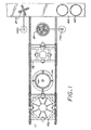
- Fig. 1 is a top plan view of a preferred form of apparatus embodying the present invention;
- Fig. 2 is a side elevational view of such apparatus;
- Fig. 3 is a vertical sectional view taken in enlarged scale along line 3-3 of Fig. 2;
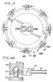
- Fig. 4 is a top plan view of a molding press forming part of the above said apparatus;
- Fig. 4A is a broken vertical sectional view taken in enlarged scale along
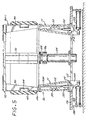
line 4A-4A of Fig. 4; - Fig. 5 is a cross-sectional side view showing a belt handler positioned above a segment loader forming part of said apparatus;
- Fig. 6 is a view similar to Fig. 5 showing the belt handler lowered to encompass the segment loader;
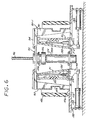
- Fig. 7 is a cross-sectional side view showing a segment handler disposed within the segment loader;
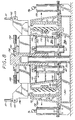
- Fig. 8 is a cross-sectional side view showing the segment handler, inner segments and rubber track disposed within the molding press;
- Fig. 9 is a cross-sectional side view showing the molding press top being lowered into the molding press lower platen;
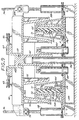
- Fig. 10 is a cross-sectional side view showing the molding press top lowered into a molding position;
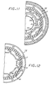
- Fig. 11 is a broken horizontal sectional view taken in enlarged scale along lines 11-11 of Fig. 10 during a rubber tractor track molding operation;
- Figs. 12 - 17 show the parts of Fig. 11 as they are disposed during and after a rubber tractor track molding operation;
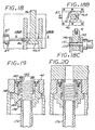
- Fig. 18A is a vertical sectional view taken in enlarged scale along
line 18A-18A of Fig. 4 showing a lifting rod connection device; - Fig. 18B is a horizontal sectional view taken along
line 18B-18B of Fig. 18A; - Fig. 18C is a vertical sectional view taken along
line 18C-18C of Fig. 7; - Figs. 19 and 20 and are vertical sectional views taken in enlarged scale along line 20-20 of Fig. 8 showing a fluid connection fitting;
- Fig. 21 is a perspective view showing a completed rubber tractor track made in accordance with the present invention;
- Fig. 22 is a vertical sectional view taken in enlarged scale along line 22-22 of Fig. 21; and
- Fig. 23 is a vertical sectional view taken along line 23-23 of Fig. 22.
-
- Referring to the drawings, in Figs. 21, 22 and 23, there is shown a completed a rubber track T made in accordance with the method and apparatus of the present invention. Such track T comprises an endless band 30 formed of
rubber 31 and calendered cord andwire cable 32 embedded in band 30. Such track T is adapted to be positioned upon the wheels and rollers of a motorized vehicle (not shown), such as a tractor or the like to support such vehicle for movement along a desired surface, such as an agricultural field. The exterior surface of band 30 is formed withintegral treads 34. The mid portion of the interior periphery of band 30 is formed with a plurality of drive lugs 35 which engage complimentary sprockets ( not shown) on the wheels or rollers of the vehicle which is supported by track T. - Track T of Figs. 21, 22 and 23 is formed by the apparatus shown in Figs. 1 through 20. Referring to Figs 1, 2 and 3, such apparatus is supported upon a concrete floor C and includes a molding press gantry MG and a segment gantry SG both horizontally movable along the floor C. The major components of the track forming apparatus embodying the present invention includes a molding press M (Figs. 4 and 8-10) having a lower platen, generally designated 40, and a mold top member, generally designated 42, a pair of belt handlers BH-1 and BH-2, a segment handler SH (Fig. 6), and a segment loader SL ( Figs. 6 and 7). The molding press gantry MG effects vertical and horizontal movement of the molding
press top member 42 relative to the molding presslower platen 40. The segment gantry SG effects vertical and horizontal movement of the segment handler SH relative to the molding press M and segment loader SL. Belt handler BH-1 is swung from a first position over a conveyor belt 44 to a second position aligned with segment loader SL so as to moveuncured belts 45 from the conveyor belt into segment loader SL. Belt handler BH-2 is swung from a position over segment loader SL to a position over the conveyor belt 44 to transfer a cured track T onto the conveyor belt. - More particularly, as shown in Figs. 1 and 2 molding press gantry MG is of conventional construction having crossbars which support four, vertical, like, equidistantly spaced electric motor driven-lifting
screw rods 46. Anotherelectric motor 47drives rollers 48 which ride onrails 49 secured tocolumns 50. Segment gantry SG is similar in construction to molding press gantry MG and includes four, vertical, like, electric motor-drivenlifting screw rods 51.Electric motor 52drive rollers 53 that ride on rails 49. - Referring to Figs. 4, 4A, 8, 9 and 10,
lower platen 40 is disposed within a depression formed in floor C and includes a base 54 from the center of which extends aguide post 56. A plurality of like, outer hydraulic cylinder andplunger closing units 58 extend upwardly from the sides of thelower platen 40. The inner portion oflower platen base 54 supports inner hydraulic cylinder andplunger units 60. Themolding press top 42 is lifted onto and off of the lower platen by the vertically reciprocallifting screw rods 46 of gantry MG (Fig. 9). The upper portion of theplungers 61 of the innercylinder plunger units 60 are affixed to a guide member generally designated 62, the upper portion of which is formed with arecess 63 selectively locked to the upper portion ofpress top 42 by horizontally movableU-shaped locking plates 64 operated by horizontally disposed fluid actuated cylinder andplunger units 66. A second plurality of horizontally extending fluid actuated cylinder and plunger units 71 are secured to thelower platen 40 to effect horizontal movement of a plurality ofmolding press segments 72 which are secured to heat-transferhollow cones 73 relative to the floor of the lower platen. A plurality ofhollow backing cones 74 andinner backing cones 74A depend from the underside of press top 42 (Fig. 9). The surface of molding press segments are formed with recesses R which form thetreads 34 of the completed tractor track T. -
Molding press top 42 includes asleeve 75 which slidably receives the upper portion ofguide member 62 to centrally align the top molding press member and the lower platen. Referring to Fig 4-A, the upper ends of the plungers of the closing cylinder andplunger units 58 are formed withknobs 76 which are releasable locked withincomplementary sockets 78 formed inblocks 78A supported on the outer periphery ofmold top 42. A plurality of fluid-operatedlocks 79 arranged around the periphery of the mold top each includes a conventional fluid-actuatedcylinder 80 that moves a U-shapedhorizontal plate 81 towards and away from the underside of theknobs 76 to connect and disconnect the cylinder andplunger units 58 to themold top 42.
Referring to Figs. 4, 9, 18A and 18B, a plurality of fluid actuatedlocks 84 are attached tomolding press top 42 abovelocks 79 to removably secure the lower ends of liftingscrew rods 46 of molding press gantry MG to the molding press top.Locks 84 include U-shaped plates 86 that are extended over the lower end ofscrew rods 46 to engage anenlargement 46A formed on the lower end of the liftingscrew rods 46 by means of conventional fluid-actuated horizontal cylinder andplunger units 87. - Referring now to Figs. 1, 2, 5 and 6, the belt handlers BH-1 and BH-2 are of like construction, and include four vertical
retractable fingers 90 horizontally slidably carried by horizontalX-shaped carrier 92, while the upper end of eachretractable finger 90 is horizontally slidably supported on one leg of the carrier. Movement of thefingers 90 is effected by conventional fluid-actuated cylinder and plunger units 94 (Fig. 6). A liftingscrew rod 96 is rigidly secured to the center ofcarrier 92. The upper end of liftingscrew 96 is threadably connected to a electric motor-driven nut member 101 (Fig. 2) secured to the free end of the boom of apower crane 102 that supports the belt handler BH-1 whereby rotation of the nut member effects vertical reciprocation of the liftingscrew rod 96. The outer surface of each of thefingers 90 is formed with adrive lug cavity 104. The lower end of each finger is formed with alip 106 that engages and supports the lower end of anuncured belt 45. - Referring to Figs. 5, 6 and 11-17, segment loader SL includes a circumferentially arranged plurality of truncated frusto-conical hollow narrow segments N and wide segments W. Each segment has an upwardly and outwardly sloping inner surface and a vertically extending outer surface. The segments are formed of a metal having a high coefficient of thermal expansion such as aluminum. The mid-portion of the outer surface of each segment is formed with a
drive lug cavity 112 which removable receives adrive lug 35. The bottom of each narrow segment N removably rests upon ashoe 114 having a bracket that extends through anopening 115 in thefloor 116 ofbase 120 of the segment loader. The lower portion of each shoe bracket is secured to the plunger of a conventional fluid-actuated horizontally extending cylinder andplunger unit 122 having its outer end affixed to the inner periphery of thebase 120. The mid-portion offloor 116 ofbase 120 is affixed to the cylinder of a vertically extending fluid-actuated cylinder andplunger unit 124. The plunger element of such unit is affixed tocylindrical lock element 126 formed with anannular groove 128. The wide segments W that removably hold anuncured drive lug 34 are similar in construction to the narrow segments and each rest removably upon a shoe having a bracket that extends through floor opening (not shown). A threadedsocket 135 is secured to theshoes 114. A tie bolt 135a extends through segments N to temporarily attach the segments to the shoes. Wide segments W are provided with a similar attachment arrangement. Referring to Fig. 7, the segment handler SH includes a downwardly tapering frusto-conical barrel 140, the angularity of which is complimentary to the angularity of the inner surfaces of the segments N and W of the segment loader SL. The interior ofbarrel 140 is provided with a plurality of conventional, horizontally extending fluid actuated cylinder andplunger units 141, the plungers of which are secured topins 142 which are removably engageable withcomplimentary sockets 143 formed in the inner walls of the inner and wide segments of the segment loader SL. - The upper end of
barrel 140 is rigidly attached to ahorizontal lifting arm 146 centrally formed with avertical cylinder 147 which is slidably engageable with thecylindrical lock element 126 of the segment loader SL. The mid-portion of liftingarm 146 carries a pair of conventional fluid-actuated cylinder andplunger units 148 which effect horizontal movement of a pair ofU-shaped locking plates 150 engageable with thegroove 128 oflock element 126. - The outer ends of each lifting
arm 146 is formed withbores 151 aligned with abore 152 formed in a blocked carried by the lower ends of the liftingscrew rods 51 of segment gantry SG. The lower end of each liftingscrew rod 51 is releasably secured to the liftingarms 146 by apin 153 attached to a fluid-actuated cylinder 153A carried by the outer ends of the lifting arms (Fig. 18C). - In the operation of the aforedescribed apparatus, a plurality of
uncured belts 45 are disposed upon the conveyor belt 44. As an uncured belt approaches the molding apparatus,fingers 90 of belt handler BH-1 are retracted and the belt handler is lowered into an uncured belt. The fourfingers 90 are then extended into engagement with the interior of thebelt 45 and the belt is transferred from the conveyor belt to a position above the segment loader SL, as shown in Figs. 1 and 5 bypower crane 153. Next, the belt is lowered into segment handler SH and thefingers 90 of the segment loader are extended into engagement with the inner surface ofbelt 45. Themovable fingers 90 of the belt handler are then retracted by means of fluid actuated cylinder andplunger units 96 and the belt handler BH-1 is then lifted out of the segment handler. The segments W are then also advanced into contact with the belt. - Referring now to Fig. 7, outward movement of the segments N and W of the segment loader SL by cylinder and
plunger units 122 and 133 forces the outer surfaces of the uncured drive lugs 35 very tightly against the inner periphery of theuncured belt 45. This operation can occur at room temperature or below 100° F. In this manner, the drive lugs are securely attached to the inner periphery of the uncured belt. If desired, an adhesive may be interposed between the drive lugs and the belt. Thereafter, the segment handler SH is lowered into the segment loader by segment gantry SG and the plunger of fluid-actuatedcylinder unit 124 pulls the segment handler SH downwardly to firmly seat the segment handler within segments N and W (Fig. 7). Thedrum 140 of the segment handler SH is engaged with the inner andouter sockets 142 of the segment handler SH by means of the fluid actuated cylinder andplunger units 141. The segments N and W may then be lifted off of thefloor 116 of the segment loader and horizontally transferred to a position over thelower platen 40 of molding press M by the segment gantry SG. Segments N and W are then lowered into the lower platen and the segments N and W are disengaged from the segment handler by removingtie rods 135 A (Fig. 8). The segment handler is returned to its table 160 by the segment gantry. - Next, the molding press gantry MG will horizontally move the
mold press top 42 to a position coaxial with thelower platen 40, and the lifting screws 46 of the mold press gantry MG lower the molding press top downwardly toward thelower platen 40 until thesockets 78 encompassknobs 76 of the cylinder and plunger units 58 (Fig. 9). TheU-shaped plates 81 are then advanced into a locked position below the knobs (Fig. 4A). The liftingscrew rods 46 are disconnected from the molding press gantry by locks 79. The inner hydraulic cylinder andplunger units 60 will raiseguide member 62 from its position of Fig. 9 to that of Fig. 10, and fluid actuated hydraulic cylinder andplunger units 66 will advance the lockingplates 64 into therecess 63 of theguide member 62 and cylinder and plunger units (Fig. 10). The inner cylinder andplunger units 60 in combination with the outer cylinder andplunger units 58 now urgemold top 42 tightly into thelower platen 40 to close the molding press. - It should be noted that once the molding press is closed, the segments N and W are at about room temperature although the
molding press segments 72 are heated. Accordingly, segments N and W provide adequate clearance (_" - ¼") to admit theuncured belt 45 and drive lugs 35. Cylinder andplunger units 72 advance the outer mold segments into contact with the outer belt surface. Previously, thecones 73 and hence outermolding press segments 72 will have been heated by steam or hot water to a desired temperature, and will remain heated during subsequent belt curing operations. The narrow and wide inner segments N and W will then be heated by steam through special fittings shown in Figs. 19 and 20, described hereinafter so as to apply compressive force between the outer molding pressinner segments 72 and the segments N and W, since the heated segments expand towards one another. The inner andouter backing cones belt 45 while forming treads in the outer periphery thereof. At the same time, the drive lugs 35 are cured and integrally bonded to the inside periphery of the belt (Fig.11). After the molding step, theguide member 62 is unlocked from the mold top and the molding pressgantry lifting rods 46 are locked to the mold top. Themold top 42 is then lifted upwardly out of thelower platen 40 by both the outer cylinder andplunger units 58 and inner cylinders andplunger units 60. Then mold gantry MG returns the mold top to its original position of Fig. 1. Next, themolding press segments 72 are retracted (Fig. 13). The cured belt T is in tight contact with the inner segments N and W at this time. - The segment handler SH is then moved back into the
lower platen 40 and transfers the segments N and W with the cured belt into the segment loader SL by segment gantry SG. Cool water is then forced into one or more of the segments N and W by fittings of the type shown in Figs. 19 and 20 so as to cause such segments to shrink away from the belt's inner periphery. The narrow segments are then retracted by cylinder and plunger units 132 until there is sufficient clearance for the belt handler BH-2fingers 170 to engage the cured belt T (Fig. 14). Wide segments W are then retracted by cylinder and plunger units 133, as indicted in Figs. 14 and 15, so as to free the cured track T. Belt handler BH-2 is then actuated to remove the cured belt T from the segment loader SL onto conveyer belt 44. - Since the segments N and W are fabricated from a metal having a high coefficient of thermal expansion, such as aluminum, such segments will move radially inwardly away from the cured track when cooled water is forced into such segments due to thermal contraction.
- Referring to Figs 16 and 17, it will be noted the facing surfaces 172 and 174 of the narrow and wide segments N and W taper radially inwardly and outwardly at an angle A. With this arrangement, extension of the narrow segments N will urge the wide segments W tightly into a complete circle when the segments contact the inner periphery of an uncured belt. When a cured belt is to be removed from the segment assembly, such taper assists in retraction of the narrow segments.
- Referring now to Figs. 9, 10, 19 and 20, steam is admitted to the removable segments N and W by the fitting F shown in Figs. 19 and 20. Fitting F includes a
pipe 176 attached to a boss 178 that is threaded to the floor of themold bottom 40. Boss 178 has acavity 180 wherein is slidably disposed asleeve 182. Sleeve 172 is biased upwardly by acoil spring 184 relative tocavity 180. An O-ring is carried by the upper end ofsleeve 182. Stop screws 185 limit upward movement ofsleeve 182. When segment W is lowered onto the floor of mold bottom 40,sleeve 182 will be pushed downwardly intocavity 180 and steam can flow throughpipe 176 into the segments. Referring to Figs. 6 and 7, a similar fitting F-3 is provided to admit cooled water into segments N and W when the temperature of such segments is to be reduced to permit a cured track T to be removed from the segment handler SH.
Claims (12)
- A method of making an endless tractor track (T) having treads (34) on its outer portion from an initially uncured belt (45) and a plurality of drive lugs (35), such method including the steps of:providing a molding press (M) having inner molding segments (N,W) and outer molding segments that are initially separated from one another;securable attaching the drive lugs onto the inner periphery of the uncured belt (45);positioning the uncured belt (45) with the drive lugs (35) attached thereto between the inner and outer molding segments (72);heating the molding press (M) and moving the inner molding segments (N,W) and outer molding segments (72) together to exert compressive pressure on the uncured belt (45) and drive lugs (35) to mold treads (34) on the outer portion of the belt (45) while bonding the drive lugs (35) to the inner periphery of the belt (45) to form an endless tractor track (T);separating the inner molding segments (N,W) and outer molding segments (72); andremoving the cured tractor track (T) from the molding press (M).
- A method as set forth in Claim 1 wherein the drive lugs (34) are attached to the inner periphery of the uncured belt (45) by pressing the drive lugs (34) against the inner surface of the uncured belt (45).
- A method as set forth in claim 1 further including the step of:providing outer molding segments (72) having recesses (R) to form treads on the outer portion of the belt (45);providing inner molding segments (N,W) having drive lug cavities (112) on their radial outer sides;releasably disposing drive lugs (35) within such cavities (112);advancing the inner molding segments (N,W) against the inner periphery of the uncured belt (45) to securely attach the drive lugs (34) to the inner periphery of the uncured belt (45);positioning the outer molding segments (72) coaxially outwardly of the inner molding segments (N,W) and the uncured belt (45) with the drive lugs (35) attached thereto;heating the outer molding segments (72) and inner molding segments (N,W) while exerting compressive pressure on the outer molding segments (72) and inner molding segments (N,W) to mold treads (34) on the outer portion of the belt (45) and cure the belt (45) while bonding the drive lugs (35) to the inner periphery of the belt (45) to form the endless tractor track (T); andremoving the completed tractor track (T) from between the molding segments (72,N,W).
- A method as set forth in claim 3 which further includes cooling the inner molding segments (N,W) to thereby retract such inner molding segments (N,W) away from the belt (45) before the completed track (T) is removed from between the molding segments (72,N,W).
- A method as set forth in claim 4 wherein the molding segments (72,N,W) are formed of aluminum.
- The method as set forth in claim 1 further including the steps of:moving the inner molding segments (N,W) and uncured belt (45) with the drive lugs (35) attached thereto into the confines of the outer molding segments (72); andadvancing the outer molding segments (72) into contact with the outer surface of the belt (45) while restraining the inner molding segments (N,W) and outer molding segments (72) against movement away from one another.
- A method as set forth in claim 6 wherein one of the inner molding segments (N or W) is retracted before the other inner molding segments (N or W) are retracted.
- Apparatus for molding an endless tractor track (T) having treads on its outer portion from an uncured rubber belt (45) and a plurality of drive lugs (35), said apparatus having:a molding press having a plurality of horizontally movable outer molding segments (72) formed with tread-defining recesses R on their inner portions, said molding press also having a plurality of inner molding segments;a segment loader (SL) that initially supports said inner molding segments (N,W) for horizontal movement, each molding segment (N,W) having a drive lug cavity (112) that initially removably holds a drive lug (35);a belt handler (BH-1) for coaxially positioning an uncured belt (45) outwardly of the inner molding segments (N,W) while said segments (N,W) are supported by the segment loader (SL);power-operated means (102) on the segment loader (SL) to urge the inner molding segments (N,W) outwardly to secure the drive lugs (35) against the inner periphery of the uncured belt (45);power-operated means on the molding press for advancing the outer molding segments against the outer surface of the uncured belt as said belt is supported on the inner molding segments;backing means to restrain the inner molding segments (N,W) and outer molding segments (72) against separating; andheating means on the molding press to effect curing of the belt (45) between the inner molding segments (N,W) and outer molding segments (72) while forming the treads (34) on the outer surface of the belt (45) and bonding the drive lugs (35) onto the inner portion of the belt (45); the apparatus characterized by:a segment handler (SH) for moving the inner molding segments (N,W), and uncured belt (45) with the drive lugs (45) attached thereto out of the segment loader (SL) into the space encompassed by the outer molding segments (72), the inner molding segments (N,W) and uncured belt (45) with the drive lugs (35) attached thereto being initially removed from the outer mold segments (72).
- Apparatus as set forth in claim 8 which further includes means for cooling the inner molding segments (N,W) before the inner segments (N,W) are retracted to free the cured belt (45).
- Apparatus as set forth in claim 8 wherein the belt handler (BH-1) includes a plurality of vertical fingers (90) that are selectively retractable whereby the plurality of fingers (90) removably engage the inner periphery of the belt (45) to effect movement thereof relative to the segment loader (SL).
- Apparatus as set forth in claim 8 wherein one of the inner molding segments (N or W) is retracted before the other inner molding segments (N or W) are retracted.
- Apparatus as set forth in claim 8 further characterized in that:the segment loader has a floor (116) that initially removably supports said inner molding segments (N,W), power-operated means to effect horizontal movement of the inner molding segments (N,W), and fastening means (79) that selectively lock the inner molding segments (N,W) against upward movement away from said floor, with the inner molding segments (N,W) being formed with outwardly facing drive lug cavities (112), each initially removably containing a drive lug (35);a segment handler (SH) for moving the inner molding segments and uncured belt (45) with the drive lugs (35) attached thereto into the molding press space to thereby be encompassed by the outer molding segments (72) after the fastening means (79) have unlocked the inner molding segments (N,W) from said floor whereafter the belt (45) is heated to cure such belt (45) while forming the treads (34) on the outer surface of the belt (45) and bonding the drive lugs (35) onto the inner portion of the belt (45) with the segment handler (SH) thereafter withdrawing the inner segments (N,W) and cured belt (45) from the molding press whereby the inner segments (N,W) can be retracted to free the cured belt (45) by said power-operated means (102).
Applications Claiming Priority (3)
| Application Number | Priority Date | Filing Date | Title |
|---|---|---|---|
| US198556 | 1998-11-23 | ||
| US09/198,556 US6177042B1 (en) | 1998-11-23 | 1998-11-23 | Method and apparatus for making integral rubber tractor tracks |
| PCT/US1999/022280 WO2000030837A1 (en) | 1998-11-23 | 1999-09-24 | Method and apparatus for making integral rubber tractor tracks |
Publications (2)
| Publication Number | Publication Date |
|---|---|
| EP1135248A1 EP1135248A1 (en) | 2001-09-26 |
| EP1135248B1 true EP1135248B1 (en) | 2002-11-20 |
Family
ID=22733879
Family Applications (1)
| Application Number | Title | Priority Date | Filing Date |
|---|---|---|---|
| EP99948463A Expired - Lifetime EP1135248B1 (en) | 1998-11-23 | 1999-09-24 | Method and apparatus for making integral rubber tractor tracks |
Country Status (10)
| Country | Link |
|---|---|
| US (1) | US6177042B1 (en) |
| EP (1) | EP1135248B1 (en) |
| JP (1) | JP2002530234A (en) |
| AU (1) | AU755431B2 (en) |
| BR (1) | BR9915511A (en) |
| CA (1) | CA2351362C (en) |
| CO (1) | CO5021139A1 (en) |
| DE (1) | DE69904078T2 (en) |
| MX (1) | MXPA01005105A (en) |
| WO (1) | WO2000030837A1 (en) |
Cited By (4)
| Publication number | Priority date | Publication date | Assignee | Title |
|---|---|---|---|---|
| DE102015205071A1 (en) | 2015-03-20 | 2016-09-22 | Contitech Transportbandsysteme Gmbh | Apparatus and method for producing a rubber crawler with tension members |
| DE102016225423A1 (en) | 2016-12-19 | 2018-06-21 | Contitech Transportbandsysteme Gmbh | Caterpillar, in particular rubber crawler |
| DE102016225396A1 (en) | 2016-12-19 | 2018-06-21 | Contitech Transportbandsysteme Gmbh | Caterpillar, in particular rubber crawler |
| DE102020214400A1 (en) | 2020-11-17 | 2022-05-19 | Contitech Antriebssysteme Gmbh | Process for manufacturing a track chain from elastomeric material |
Families Citing this family (9)
| Publication number | Priority date | Publication date | Assignee | Title |
|---|---|---|---|---|
| FR2811934A1 (en) * | 2000-07-24 | 2002-01-25 | Michelin Soc Tech | METHOD OF MANUFACTURING A TRACK AND UNMOLDING DEVICE |
| US6554377B2 (en) * | 2001-07-19 | 2003-04-29 | The Goodyear Tire & Rubber Company | Rubber track and improved method and method for producing the track |
| AU2005220201B2 (en) * | 2001-07-19 | 2007-08-02 | Veyance Technologies, Inc. | Mold for a rubber track |
| WO2003055659A1 (en) * | 2001-12-26 | 2003-07-10 | Societe De Technologie Michelin | Method for moulding under pressure non-vulcanized rubber material particles |
| US6668440B1 (en) * | 2002-12-31 | 2003-12-30 | The Goodyear Tire & Rubber Company | Control system for adjacent pitch in press cured positive drive belts |
| US7189069B2 (en) * | 2003-10-03 | 2007-03-13 | The Goodyear Tire & Rubber Company | Mold for forming an annular tread belt |
| JP4837341B2 (en) * | 2005-09-13 | 2011-12-14 | 株式会社ブリヂストン | Rubber crawler manufacturing method and apparatus |
| US8807984B2 (en) | 2011-10-26 | 2014-08-19 | Bridgestone Bandag, Llc | Molded article extractor and method |
| DE102015221168A1 (en) * | 2015-10-29 | 2017-05-04 | Contitech Antriebssysteme Gmbh | Method and manufacturing device for producing a double toothed belt |
Family Cites Families (31)
| Publication number | Priority date | Publication date | Assignee | Title |
|---|---|---|---|---|
| US1579922A (en) | 1922-11-01 | 1926-04-06 | Goodrich Co B F | Method of manufacturing tires |
| US1779376A (en) | 1923-06-12 | 1930-10-21 | Fisk Rubber Co | Tire-forming machine |
| US1779377A (en) | 1926-08-23 | 1930-10-21 | Fisk Rubber Co | Tire-forming machine |
| US1665870A (en) | 1926-08-26 | 1928-04-10 | Goodyear Tire & Rubber | Shaping device |
| US1715973A (en) | 1927-07-30 | 1929-06-04 | Morgan & Wright | Method of and apparatus for manufacturing pneumatic tires |
| US1763589A (en) | 1927-11-18 | 1930-06-10 | Goodyear Tire & Rubber | Tire-forming machine |
| US1949443A (en) | 1930-12-12 | 1934-03-06 | Morgan & Wright | Tire shaping apparatus |
| US1986092A (en) | 1931-06-11 | 1935-01-01 | Morgan & Wright | Tire shaping machine |
| US2381395A (en) * | 1943-07-08 | 1945-08-07 | Firestone Tire & Rubber Co | Vulcanizing mold |
| US2747225A (en) | 1951-10-25 | 1956-05-29 | Pirelli | Apparatus for shaping tire casings |
| US3222716A (en) | 1959-01-22 | 1965-12-14 | Edward J Harris | Tire curing press and unloading apparatus therefor |
| GB1292929A (en) * | 1970-07-08 | 1972-10-18 | Uk Ni I K I Razrabotke Mashin | Device for moulding and vulcanization of circular rubber articles |
| US3791897A (en) * | 1971-06-16 | 1974-02-12 | Bombardier Ltd | Method and apparatus for making endless belts |
| IT1010109B (en) | 1974-04-26 | 1977-01-10 | Pirelli | MOLD FOR THE MANUFACTURING OF DOUBLE-TOOTHED TIMING BELTS AND TIMING BELTS SO OBTAINED |
| ZA742928B (en) | 1974-05-08 | 1975-08-27 | W Stinnes | Centrifugal moulding |
| US4184822A (en) | 1975-09-29 | 1980-01-22 | The Gates Rubber Company | Apparatus for making power transmission belting |
| CA1039467A (en) | 1975-12-24 | 1978-10-03 | Cedric W. Mcleod | Moulding press |
| US4207052A (en) * | 1976-07-16 | 1980-06-10 | Caterpillar Tractor Co. | Curing mold for curing replaceable tread and track belts |
| US4263083A (en) | 1979-07-20 | 1981-04-21 | The Goodyear Tire & Rubber Company | Building and curing an inextensible belt structure for a tire assembly |
| US4575438A (en) * | 1980-11-19 | 1986-03-11 | Ohio Machine Company, Inc. | Tubeless tire curing method |
| JPS58163638A (en) | 1982-03-25 | 1983-09-28 | Mitsuboshi Belting Ltd | Fabricated mold for manufacture of toothed belt made of rubber |
| JPS60159039A (en) * | 1984-01-30 | 1985-08-20 | Mitsuboshi Belting Ltd | Manufacture of double timing belt |
| FR2571310B1 (en) * | 1984-10-04 | 1987-01-30 | Michelin & Cie | PREVULCANIZED TREAD FOR RETREADING TIRES AND APPARATUS FOR PRODUCING SUCH A TREAD |
| WO1991004145A1 (en) | 1989-09-18 | 1991-04-04 | Herbert Clarence Spiller | Moulding of articles in plastics |
| IT1234666B (en) | 1989-09-21 | 1992-05-26 | Mai Spa | PROCEDURE FOR THE REALIZATION OF RUBBER TRACKS AND TRACK SO MADE |
| US5204036A (en) * | 1989-12-29 | 1993-04-20 | Macmillan Kenneth T | Method of molding tires |
| IT1244635B (en) * | 1991-03-26 | 1994-08-08 | Firestone Int Dev Spa | METHOD AND UNIT FOR ROLLING MULTI-LAYER PRODUCTS OF ELASTOMERIC MATERIAL IN THE RAW STATE |
| JP2686375B2 (en) * | 1991-04-23 | 1997-12-08 | 三菱重工業株式会社 | Tire manufacturing equipment |
| IT1250330B (en) * | 1991-10-31 | 1995-04-07 | Firestone Int Dev Spa | METHOD FOR THE REALIZATION OF AN ANNULAR TREAD HEAD WITHOUT JUNCTION. |
| US5460771A (en) * | 1992-10-16 | 1995-10-24 | Itt Corporation | Process for producing corrugated multi-layer tubing having layers of differing plastic characteristics |
| US5536464A (en) * | 1994-11-15 | 1996-07-16 | Bridgestone/Firestone, Inc. | Apparatus and method for curing endless rubber track |
-
1998
- 1998-11-23 US US09/198,556 patent/US6177042B1/en not_active Expired - Fee Related
-
1999
- 1999-09-24 WO PCT/US1999/022280 patent/WO2000030837A1/en not_active Ceased
- 1999-09-24 EP EP99948463A patent/EP1135248B1/en not_active Expired - Lifetime
- 1999-09-24 AU AU61632/99A patent/AU755431B2/en not_active Ceased
- 1999-09-24 JP JP2000583695A patent/JP2002530234A/en not_active Withdrawn
- 1999-09-24 DE DE69904078T patent/DE69904078T2/en not_active Expired - Fee Related
- 1999-09-24 CA CA002351362A patent/CA2351362C/en not_active Expired - Fee Related
- 1999-09-24 BR BR9915511-7A patent/BR9915511A/en active Search and Examination
- 1999-09-24 MX MXPA01005105A patent/MXPA01005105A/en not_active IP Right Cessation
- 1999-11-18 CO CO99072514A patent/CO5021139A1/en unknown
Cited By (7)
| Publication number | Priority date | Publication date | Assignee | Title |
|---|---|---|---|---|
| DE102015205071A1 (en) | 2015-03-20 | 2016-09-22 | Contitech Transportbandsysteme Gmbh | Apparatus and method for producing a rubber crawler with tension members |
| WO2016150580A1 (en) | 2015-03-20 | 2016-09-29 | Contitech Transportbandsysteme Gmbh | Device and method for producing a rubber caterpillar track with tensile members |
| DE102016225423A1 (en) | 2016-12-19 | 2018-06-21 | Contitech Transportbandsysteme Gmbh | Caterpillar, in particular rubber crawler |
| DE102016225396A1 (en) | 2016-12-19 | 2018-06-21 | Contitech Transportbandsysteme Gmbh | Caterpillar, in particular rubber crawler |
| WO2018114084A1 (en) | 2016-12-19 | 2018-06-28 | Contitech Transportbandsysteme Gmbh | Crawler track, in particular rubber crawler track |
| WO2018114085A1 (en) | 2016-12-19 | 2018-06-28 | Contitech Transportbandsysteme Gmbh | Crawler track, in particular rubber crawler track |
| DE102020214400A1 (en) | 2020-11-17 | 2022-05-19 | Contitech Antriebssysteme Gmbh | Process for manufacturing a track chain from elastomeric material |
Also Published As
| Publication number | Publication date |
|---|---|
| DE69904078D1 (en) | 2003-01-02 |
| EP1135248A1 (en) | 2001-09-26 |
| WO2000030837A1 (en) | 2000-06-02 |
| US6177042B1 (en) | 2001-01-23 |
| MXPA01005105A (en) | 2002-06-04 |
| CO5021139A1 (en) | 2001-03-27 |
| CA2351362C (en) | 2006-09-05 |
| BR9915511A (en) | 2001-08-07 |
| AU6163299A (en) | 2000-06-13 |
| DE69904078T2 (en) | 2003-07-31 |
| JP2002530234A (en) | 2002-09-17 |
| AU755431B2 (en) | 2002-12-12 |
| CA2351362A1 (en) | 2000-06-02 |
Similar Documents
| Publication | Publication Date | Title |
|---|---|---|
| EP1135248B1 (en) | Method and apparatus for making integral rubber tractor tracks | |
| AU2002300014B2 (en) | A rubber track and improved mold and method for producing the track | |
| US6086811A (en) | Molding system for rubber tractor tracks | |
| JP3771584B2 (en) | Combined thermal drape vacuum former | |
| DE212021000006U1 (en) | Road to rail dual purpose track laying machine for urban rail transport projects | |
| CN112921760A (en) | Width adjustable die device | |
| CA1207963A (en) | Tire press, loader and method | |
| WO2000048825A1 (en) | Method and apparatus for making integral rubber tractor tracks | |
| US4640421A (en) | Truck crane conversion to crawler crane | |
| JP3693349B2 (en) | Apparatus and method for curing endless rubber tracks | |
| JP2000503607A (en) | Apparatus and method for curing endless rubber tracks | |
| US6662421B1 (en) | Method and apparatus for installation of rubber tracks on vehicles | |
| US20020093125A1 (en) | Automated process and apparatus for forming a molded article | |
| CN215851305U (en) | Transfer device for glass fiber reinforced plastic forming die | |
| RU2717323C1 (en) | Method for manufacturing of temporary road pavements from tread bands of used trucks tires and production line for its implementation | |
| WO2000016969A1 (en) | Tire retreading apparatus | |
| JPS591842Y2 (en) | Collar attachment/detachment device | |
| AU2005220201B2 (en) | Mold for a rubber track | |
| CA1091408A (en) | Apparatus for positioning and curing a pre-shaped tire carcass | |
| CN115419112A (en) | Well lid production equipment and method | |
| JP3045524B2 (en) | Press mold for escalator handrail | |
| JPH0368200B2 (en) | ||
| TW201829146A (en) | Tire vulcanizing apparatus |
Legal Events
| Date | Code | Title | Description |
|---|---|---|---|
| PUAI | Public reference made under article 153(3) epc to a published international application that has entered the european phase |
Free format text: ORIGINAL CODE: 0009012 |
|
| 17P | Request for examination filed |
Effective date: 20010625 |
|
| AK | Designated contracting states |
Kind code of ref document: A1 Designated state(s): AT BE CH CY DE DK ES FI FR GB GR IE IT LI LU MC NL PT SE |
|
| GRAG | Despatch of communication of intention to grant |
Free format text: ORIGINAL CODE: EPIDOS AGRA |
|
| RAP1 | Party data changed (applicant data changed or rights of an application transferred) |
Owner name: THE GOODYEAR TIRE & RUBBER COMPANY |
|
| 17Q | First examination report despatched |
Effective date: 20020207 |
|
| GRAG | Despatch of communication of intention to grant |
Free format text: ORIGINAL CODE: EPIDOS AGRA |
|
| GRAH | Despatch of communication of intention to grant a patent |
Free format text: ORIGINAL CODE: EPIDOS IGRA |
|
| GRAH | Despatch of communication of intention to grant a patent |
Free format text: ORIGINAL CODE: EPIDOS IGRA |
|
| GRAA | (expected) grant |
Free format text: ORIGINAL CODE: 0009210 |
|
| AK | Designated contracting states |
Kind code of ref document: B1 Designated state(s): DE FR GB |
|
| REG | Reference to a national code |
Ref country code: GB Ref legal event code: FG4D |
|
| REF | Corresponds to: |
Ref document number: 69904078 Country of ref document: DE Date of ref document: 20030102 |
|
| ET | Fr: translation filed | ||
| PG25 | Lapsed in a contracting state [announced via postgrant information from national office to epo] |
Ref country code: GB Free format text: LAPSE BECAUSE OF NON-PAYMENT OF DUE FEES Effective date: 20030924 |
|
| PLBE | No opposition filed within time limit |
Free format text: ORIGINAL CODE: 0009261 |
|
| STAA | Information on the status of an ep patent application or granted ep patent |
Free format text: STATUS: NO OPPOSITION FILED WITHIN TIME LIMIT |
|
| 26N | No opposition filed |
Effective date: 20030821 |
|
| GBPC | Gb: european patent ceased through non-payment of renewal fee |
Effective date: 20030924 |
|
| PGFP | Annual fee paid to national office [announced via postgrant information from national office to epo] |
Ref country code: DE Payment date: 20070928 Year of fee payment: 9 |
|
| PGFP | Annual fee paid to national office [announced via postgrant information from national office to epo] |
Ref country code: FR Payment date: 20070904 Year of fee payment: 9 |
|
| REG | Reference to a national code |
Ref country code: FR Ref legal event code: ST Effective date: 20090529 |
|
| PG25 | Lapsed in a contracting state [announced via postgrant information from national office to epo] |
Ref country code: DE Free format text: LAPSE BECAUSE OF NON-PAYMENT OF DUE FEES Effective date: 20090401 |
|
| PG25 | Lapsed in a contracting state [announced via postgrant information from national office to epo] |
Ref country code: FR Free format text: LAPSE BECAUSE OF NON-PAYMENT OF DUE FEES Effective date: 20080930 |