EP1135225B1 - Method and device for feeding of long objects - Google Patents
Method and device for feeding of long objects Download PDFInfo
- Publication number
- EP1135225B1 EP1135225B1 EP99946559A EP99946559A EP1135225B1 EP 1135225 B1 EP1135225 B1 EP 1135225B1 EP 99946559 A EP99946559 A EP 99946559A EP 99946559 A EP99946559 A EP 99946559A EP 1135225 B1 EP1135225 B1 EP 1135225B1
- Authority
- EP
- European Patent Office
- Prior art keywords
- signals
- working machine
- feeding
- pulse transmitter
- speed
- Prior art date
- Legal status (The legal status is an assumption and is not a legal conclusion. Google has not performed a legal analysis and makes no representation as to the accuracy of the status listed.)
- Expired - Lifetime
Links
- 238000000034 method Methods 0.000 title claims abstract description 11
- 239000000463 material Substances 0.000 claims abstract description 25
- 230000008054 signal transmission Effects 0.000 claims 2
- 238000005452 bending Methods 0.000 description 2
- 238000005520 cutting process Methods 0.000 description 2
- 238000004080 punching Methods 0.000 description 2
- 230000001360 synchronised effect Effects 0.000 description 2
- 238000010276 construction Methods 0.000 description 1
- 230000000694 effects Effects 0.000 description 1
- 239000002184 metal Substances 0.000 description 1
- 238000012544 monitoring process Methods 0.000 description 1
Images
Classifications
-
- B—PERFORMING OPERATIONS; TRANSPORTING
- B21—MECHANICAL METAL-WORKING WITHOUT ESSENTIALLY REMOVING MATERIAL; PUNCHING METAL
- B21D—WORKING OR PROCESSING OF SHEET METAL OR METAL TUBES, RODS OR PROFILES WITHOUT ESSENTIALLY REMOVING MATERIAL; PUNCHING METAL
- B21D43/00—Feeding, positioning or storing devices combined with, or arranged in, or specially adapted for use in connection with, apparatus for working or processing sheet metal, metal tubes or metal profiles; Associations therewith of cutting devices
- B21D43/02—Advancing work in relation to the stroke of the die or tool
- B21D43/021—Control or correction devices in association with moving strips
Definitions
- the present invention is for a method and a means for feeding of strip or band material to working machines in which the goods is worked upon and split up in individual parts.
- the invention is for feeding of metal bands to presses for bending, punching and cutting (see for example US-A-4 553 445).
- the roll feeders are usually connected to an working machine for example an eccentric press, hydraulic press or the like. These are often automated and continuously working machines at it is a requirement that the feed in fully agrees with the speed of operation and need for material of the working machine at each individual moment of operation, the feed in has to be synchronised with the working machine. Nor shall the roll feeder work at a higher speed than the process requires as unnecessarily high speed brings with it raised standards of the included components and a greater wear than at correctly adjusted speed. If optimal synchronised operation shall be possible then the roll feeder shall feed the workpiece slowly when the working machine runs slowly and when it works fast the roll feeder shall feed fast. Roll feeders which are under forced control by a mechanical connection with the working machine, for example the eccentric shaft of a press, follow the speed of the working machine but there are great difficulties at the setting of the feed length at a continuous or long workpiece.
- the object of the present invention is at method and a control system at which the feed rate of a material feeding device, for example a roll feeder, automatically adjusts itself relative to the speed of the working machine.
- a material feeding device for example a roll feeder
- the invention is defined by the features which are mentioned in claims 1 or 6. Characteristics of further embodiments of the invention are given in the depending claims.
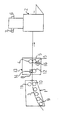
- Material in the shape of a continuous strip 3 is supplied to the roll feeder from a storage, a roll or the like. Over the support rolls 9, 10, 11 which are arranged in a bowshape within the supporting lane 1 the material is fed in between the feed rolls 4 and 5 and further on to an excenter press 2. The distance between the roll feeder and the excenter press is often much smaller than as shown in the figure.
- Den upper feed roll 4 is forced downwards by means of a pneumatic cylinder or in any other suitable way.
- the feed rolls are driven by a motor 15 which works on the lower feed roll 5, the upper feed roll 4 is driven by the lower feed roll 5 by means of gear wheels.
- a measuring wheel 8 having a first pulse transmitter 14 is arranged adjacent to the feed rolls and in known manner it produces pulses relative to the length and speed of the feeding of material.
- the measuring wheel is forced downwards against the strip of material which underneath is supported by a lower support wheel or support roll 12.
- Preferably the measuring wheel is arranged ahead of the feed rolls in the direction of conveyance of the material.
- a pulse transmitter 16 may be arranged so that pulses are received directly from the driving motor 15.
- a second pulse transmitter 7 is arranged so that it delivers pulses relative to the rotation of the eccentric shaft 6.
- the signals from the pulse transmitters are input into a control system with a processor in which the signals are processed.
- the signals from the second pulse transmitter are then not only used to determine the position of the eccentric shaft but also to determine its speed of rotation.
- the first pulse transmitter may give signals which correspond to the speed of the feed strip and the length of fed material during a cycle of operation.
- Various functions which are controlled by the control system are when feed of material is to be started and when it must be concluded and also various monitoring functions, for example that a part which has been worked upon is removed from the tool of the excenter press.
- the method of the invention also comprises adapting the speed of the feeding of material to the speed of rotation of the eccentric shaft which may be achieved thereby that the number of pulses per unit time from the second pulse transmitter of the control system is compared to the set length of feeding for each cycle of operation.
- the processor of the control system then calculates the optimum speed of the feed rolls 4, 5.
- the invention is above described with reference to an eccentric press but it is not limited to this kind of working machines.
- Other machines with which the invention may find uses are other kinds of presses, punching and cutting machines, bending machines and the like.
- other transmitters of the same or other kinds may be connected to the control system and these may affect for example the allowed limiting values.
Landscapes
- Engineering & Computer Science (AREA)
- Mechanical Engineering (AREA)
- Controlling Rewinding, Feeding, Winding, Or Abnormalities Of Webs (AREA)
- Press Drives And Press Lines (AREA)
- Advancing Webs (AREA)
- Specific Conveyance Elements (AREA)
- Forging (AREA)
- Manufacturing Of Electric Cables (AREA)
Abstract
Description
Claims (6)
- Method for intermittent feeding of long objects (3) to working machines (2) where the feed rate is controlled in relation to the speed of the working machine characterized in that the control of the feed rate is made by means of a control system with a processor supplied with signals which correspond to the speed and position of the working machine and to the rate and fed length of the fed material (3).
- Method according to claim 1 characterized in that the control system is supplied with signals from a first pulse transmitter (14, 16) which gives signals from the fed goods (3) or its driving means (15) and a second pulse transmitter (7) which gives signals from the working machine (2).
- method according to claim 2 characterized in that the second pulse transmitter (7) gives signals from a driving shaft (6) of the working machine (2).
- Method according to claim 3 characterized in that the second pulse transmitter (7) gives signals from the eccentric shaft (6) of an excenter press.
- Method according to any of the preceding claims characterized in that the material is fed by a roll feeder (13).
- Means for controlling the feeding of material of long or strip material (3) to a working machine (2) characterized in that it comprises a first pulse transmitter (14, 16) for transmission of signals from the fed material or its driving means, a second pulse transmitter (7) for transmission of signals from the driving means of the working machine, a control system having a processor in which the signals from the pulse transmitters is processed so that the rate of feeding is controlled by signals from the controlling system.
Applications Claiming Priority (3)
| Application Number | Priority Date | Filing Date | Title |
|---|---|---|---|
| SE9803044A SE512677C2 (en) | 1998-09-08 | 1998-09-08 | Methods and apparatus for feeding elongated objects |
| SE9803044 | 1998-09-08 | ||
| PCT/SE1999/001540 WO2000016929A1 (en) | 1998-09-08 | 1999-09-03 | Method and device for feeding of long objects |
Publications (2)
| Publication Number | Publication Date |
|---|---|
| EP1135225A1 EP1135225A1 (en) | 2001-09-26 |
| EP1135225B1 true EP1135225B1 (en) | 2003-11-19 |
Family
ID=20412528
Family Applications (1)
| Application Number | Title | Priority Date | Filing Date |
|---|---|---|---|
| EP99946559A Expired - Lifetime EP1135225B1 (en) | 1998-09-08 | 1999-09-03 | Method and device for feeding of long objects |
Country Status (8)
| Country | Link |
|---|---|
| US (1) | US6422445B2 (en) |
| EP (1) | EP1135225B1 (en) |
| AT (1) | ATE254517T1 (en) |
| CA (1) | CA2340881A1 (en) |
| DE (2) | DE1135225T1 (en) |
| NO (1) | NO20010710L (en) |
| SE (1) | SE512677C2 (en) |
| WO (1) | WO2000016929A1 (en) |
Families Citing this family (1)
| Publication number | Priority date | Publication date | Assignee | Title |
|---|---|---|---|---|
| CN104190778B (en) * | 2014-07-31 | 2016-03-09 | 上海永太汽车零部件厂 | Coiled material cutter sweep |
Family Cites Families (13)
| Publication number | Priority date | Publication date | Assignee | Title |
|---|---|---|---|---|
| US3762198A (en) * | 1972-03-24 | 1973-10-02 | Gen Electric | Apparatus and methods for handling strip material |
| US3817067A (en) * | 1972-09-05 | 1974-06-18 | Minster Machine Co | Stock supply system |
| US4078416A (en) * | 1976-10-07 | 1978-03-14 | The Minster Machine Company | Method and apparatus for feeding strip stock into a machine |
| US4134334A (en) * | 1977-09-19 | 1979-01-16 | F. J. Littell Machine Company | Automated lock device for press feed belt drives |
| SE437861B (en) * | 1983-02-03 | 1985-03-18 | Goran Palmers | DEVICE FOR MEDIUM HYDRAULIC CYLINDER OPERATED MACHINERY WITH ONE OF A DRIVE CELL THROUGH AN ENERGY CUMULATOR DRIVE PUMP |
| US4561581A (en) * | 1983-02-07 | 1985-12-31 | Kelly Thomas A | Web accumulator with arcuate guide supports |
| US4553445A (en) * | 1984-03-02 | 1985-11-19 | Holbrook Joe C | Intermittent movement-controlling indexing shuttle device |
| WO1988004990A1 (en) * | 1986-12-29 | 1988-07-14 | Mitoshi Ishii | Method of operating press and servo controller therefor |
| US4953808A (en) * | 1988-08-08 | 1990-09-04 | Perfecto Industries, Inc. | Apparatus for supplying a sheet metal strip to a press |
| ATE147298T1 (en) * | 1990-10-12 | 1997-01-15 | Bruderer Ag | METHOD FOR CONTROLLING THE FEEDING OF A PROCESSING MACHINE WITH STRIP-SHAPED MATERIAL AND DEVICE THEREFOR |
| US5224053A (en) * | 1991-01-22 | 1993-06-29 | Dayton Reliable Tool & Mfg. Co. | Interactive control for can end systems |
| US5392977A (en) * | 1993-11-09 | 1995-02-28 | Sankyo Seisakusho Co. | Coil material supply apparatus for an intermittent feed device |
| DE19648896A1 (en) * | 1996-01-19 | 1997-07-24 | Minster Machine Co | Die transfer control system with damped successor |
-
1998
- 1998-09-08 SE SE9803044A patent/SE512677C2/en not_active IP Right Cessation
-
1999
- 1999-09-03 EP EP99946559A patent/EP1135225B1/en not_active Expired - Lifetime
- 1999-09-03 AT AT99946559T patent/ATE254517T1/en not_active IP Right Cessation
- 1999-09-03 DE DE1135225T patent/DE1135225T1/en active Pending
- 1999-09-03 CA CA002340881A patent/CA2340881A1/en not_active Abandoned
- 1999-09-03 WO PCT/SE1999/001540 patent/WO2000016929A1/en not_active Ceased
- 1999-09-03 DE DE69912986T patent/DE69912986T2/en not_active Expired - Fee Related
-
2001
- 2001-02-12 NO NO20010710A patent/NO20010710L/en not_active Application Discontinuation
- 2001-02-22 US US09/789,812 patent/US6422445B2/en not_active Expired - Fee Related
Also Published As
| Publication number | Publication date |
|---|---|
| SE512677C2 (en) | 2000-05-02 |
| NO20010710D0 (en) | 2001-02-12 |
| DE69912986T2 (en) | 2004-09-02 |
| DE1135225T1 (en) | 2002-07-04 |
| US6422445B2 (en) | 2002-07-23 |
| CA2340881A1 (en) | 2000-03-30 |
| NO20010710L (en) | 2001-02-12 |
| US20010006182A1 (en) | 2001-07-05 |
| SE9803044L (en) | 2000-03-09 |
| ATE254517T1 (en) | 2003-12-15 |
| EP1135225A1 (en) | 2001-09-26 |
| SE9803044D0 (en) | 1998-09-08 |
| WO2000016929A1 (en) | 2000-03-30 |
| DE69912986D1 (en) | 2003-12-24 |
Similar Documents
| Publication | Publication Date | Title |
|---|---|---|
| EP0832833A3 (en) | Sheet supplying apparatus | |
| CA2220073A1 (en) | Method and apparatus for cutting dough products | |
| CN217393555U (en) | Efficient beat doffer | |
| EP0800894A3 (en) | Method and means to control a motor feed drive | |
| CN2905301Y (en) | Full-automatic laser cloth-leather cutting machine | |
| US20010006182A1 (en) | Method and device for feeding of long objects | |
| US6308546B1 (en) | Swaging machine | |
| KR100346978B1 (en) | A punching and cutting apparatus | |
| EP0354052A3 (en) | Installation for ultrasonic dimensional treatment | |
| WO1996029167A3 (en) | Method apparatus for attaching inserts | |
| AU1240597A (en) | Process for extruding a section or the like from an ingot and a device for that purpose | |
| CN209520300U (en) | A kind of process equipment of arch steel | |
| EP0468932A1 (en) | A device for the separation of bags or finished items, pre-cut and formed by a thermal or high frequency welding process, from one or more continuous strips of heat-sealable plastic film | |
| JPH07314242A (en) | Automatic transferring and working device for steel product | |
| JPH0372399B2 (en) | ||
| US20220030774A1 (en) | Press for producing bales of forage and the like | |
| JP4676590B2 (en) | Shearing machine | |
| CN206105987U (en) | Belt formula clicker | |
| JP2521786B2 (en) | Punching press | |
| CN210629295U (en) | Automatic punching machine for stator and rotor sheets of motor | |
| CN210163718U (en) | Automatic belt cutting machine | |
| CN210061294U (en) | Punch for half-cutting and movable half-cutting machine | |
| CA2093383A1 (en) | Method and apparatus for adjusting press operating conditions depending upon dies used | |
| CN215470211U (en) | Armored thermocouple cable grooving device | |
| CN221231383U (en) | Radiating fin processing device |
Legal Events
| Date | Code | Title | Description |
|---|---|---|---|
| PUAI | Public reference made under article 153(3) epc to a published international application that has entered the european phase |
Free format text: ORIGINAL CODE: 0009012 |
|
| 17P | Request for examination filed |
Effective date: 20010301 |
|
| AK | Designated contracting states |
Kind code of ref document: A1 Designated state(s): AT BE CH CY DE DK ES FI FR GB GR IE IT LI LU MC NL PT SE |
|
| DET | De: translation of patent claims | ||
| GRAH | Despatch of communication of intention to grant a patent |
Free format text: ORIGINAL CODE: EPIDOS IGRA |
|
| 17Q | First examination report despatched |
Effective date: 20030211 |
|
| GRAS | Grant fee paid |
Free format text: ORIGINAL CODE: EPIDOSNIGR3 |
|
| GRAA | (expected) grant |
Free format text: ORIGINAL CODE: 0009210 |
|
| AK | Designated contracting states |
Kind code of ref document: B1 Designated state(s): AT BE CH CY DE DK ES FI FR GB GR IE IT LI LU MC NL PT SE |
|
| PG25 | Lapsed in a contracting state [announced via postgrant information from national office to epo] |
Ref country code: NL Free format text: LAPSE BECAUSE OF FAILURE TO SUBMIT A TRANSLATION OF THE DESCRIPTION OR TO PAY THE FEE WITHIN THE PRESCRIBED TIME-LIMIT Effective date: 20031119 Ref country code: LI Free format text: LAPSE BECAUSE OF FAILURE TO SUBMIT A TRANSLATION OF THE DESCRIPTION OR TO PAY THE FEE WITHIN THE PRESCRIBED TIME-LIMIT Effective date: 20031119 Ref country code: FI Free format text: LAPSE BECAUSE OF FAILURE TO SUBMIT A TRANSLATION OF THE DESCRIPTION OR TO PAY THE FEE WITHIN THE PRESCRIBED TIME-LIMIT Effective date: 20031119 Ref country code: CY Free format text: LAPSE BECAUSE OF FAILURE TO SUBMIT A TRANSLATION OF THE DESCRIPTION OR TO PAY THE FEE WITHIN THE PRESCRIBED TIME-LIMIT Effective date: 20031119 Ref country code: CH Free format text: LAPSE BECAUSE OF FAILURE TO SUBMIT A TRANSLATION OF THE DESCRIPTION OR TO PAY THE FEE WITHIN THE PRESCRIBED TIME-LIMIT Effective date: 20031119 Ref country code: BE Free format text: LAPSE BECAUSE OF FAILURE TO SUBMIT A TRANSLATION OF THE DESCRIPTION OR TO PAY THE FEE WITHIN THE PRESCRIBED TIME-LIMIT Effective date: 20031119 Ref country code: AT Free format text: LAPSE BECAUSE OF FAILURE TO SUBMIT A TRANSLATION OF THE DESCRIPTION OR TO PAY THE FEE WITHIN THE PRESCRIBED TIME-LIMIT Effective date: 20031119 |
|
| REG | Reference to a national code |
Ref country code: GB Ref legal event code: FG4D |
|
| REG | Reference to a national code |
Ref country code: CH Ref legal event code: EP |
|
| REF | Corresponds to: |
Ref document number: 69912986 Country of ref document: DE Date of ref document: 20031224 Kind code of ref document: P |
|
| REG | Reference to a national code |
Ref country code: IE Ref legal event code: FG4D |
|
| PG25 | Lapsed in a contracting state [announced via postgrant information from national office to epo] |
Ref country code: SE Free format text: LAPSE BECAUSE OF FAILURE TO SUBMIT A TRANSLATION OF THE DESCRIPTION OR TO PAY THE FEE WITHIN THE PRESCRIBED TIME-LIMIT Effective date: 20040219 Ref country code: GR Free format text: LAPSE BECAUSE OF FAILURE TO SUBMIT A TRANSLATION OF THE DESCRIPTION OR TO PAY THE FEE WITHIN THE PRESCRIBED TIME-LIMIT Effective date: 20040219 Ref country code: DK Free format text: LAPSE BECAUSE OF FAILURE TO SUBMIT A TRANSLATION OF THE DESCRIPTION OR TO PAY THE FEE WITHIN THE PRESCRIBED TIME-LIMIT Effective date: 20040219 |
|
| PG25 | Lapsed in a contracting state [announced via postgrant information from national office to epo] |
Ref country code: ES Free format text: LAPSE BECAUSE OF FAILURE TO SUBMIT A TRANSLATION OF THE DESCRIPTION OR TO PAY THE FEE WITHIN THE PRESCRIBED TIME-LIMIT Effective date: 20040302 |
|
| NLV1 | Nl: lapsed or annulled due to failure to fulfill the requirements of art. 29p and 29m of the patents act | ||
| REG | Reference to a national code |
Ref country code: CH Ref legal event code: PL |
|
| PGFP | Annual fee paid to national office [announced via postgrant information from national office to epo] |
Ref country code: GB Payment date: 20040811 Year of fee payment: 6 |
|
| ET | Fr: translation filed | ||
| PGFP | Annual fee paid to national office [announced via postgrant information from national office to epo] |
Ref country code: FR Payment date: 20040831 Year of fee payment: 6 |
|
| PG25 | Lapsed in a contracting state [announced via postgrant information from national office to epo] |
Ref country code: LU Free format text: LAPSE BECAUSE OF NON-PAYMENT OF DUE FEES Effective date: 20040903 Ref country code: IE Free format text: LAPSE BECAUSE OF NON-PAYMENT OF DUE FEES Effective date: 20040903 |
|
| PLBE | No opposition filed within time limit |
Free format text: ORIGINAL CODE: 0009261 |
|
| STAA | Information on the status of an ep patent application or granted ep patent |
Free format text: STATUS: NO OPPOSITION FILED WITHIN TIME LIMIT |
|
| PGFP | Annual fee paid to national office [announced via postgrant information from national office to epo] |
Ref country code: DE Payment date: 20040927 Year of fee payment: 6 |
|
| PG25 | Lapsed in a contracting state [announced via postgrant information from national office to epo] |
Ref country code: MC Free format text: LAPSE BECAUSE OF NON-PAYMENT OF DUE FEES Effective date: 20040930 |
|
| 26N | No opposition filed |
Effective date: 20040820 |
|
| REG | Reference to a national code |
Ref country code: IE Ref legal event code: MM4A |
|
| PG25 | Lapsed in a contracting state [announced via postgrant information from national office to epo] |
Ref country code: IT Free format text: LAPSE BECAUSE OF NON-PAYMENT OF DUE FEES Effective date: 20050903 Ref country code: GB Free format text: LAPSE BECAUSE OF NON-PAYMENT OF DUE FEES Effective date: 20050903 |
|
| PG25 | Lapsed in a contracting state [announced via postgrant information from national office to epo] |
Ref country code: DE Free format text: LAPSE BECAUSE OF NON-PAYMENT OF DUE FEES Effective date: 20060401 |
|
| GBPC | Gb: european patent ceased through non-payment of renewal fee |
Effective date: 20050903 |
|
| PG25 | Lapsed in a contracting state [announced via postgrant information from national office to epo] |
Ref country code: FR Free format text: LAPSE BECAUSE OF NON-PAYMENT OF DUE FEES Effective date: 20060531 |
|
| REG | Reference to a national code |
Ref country code: FR Ref legal event code: ST Effective date: 20060531 |
|
| PG25 | Lapsed in a contracting state [announced via postgrant information from national office to epo] |
Ref country code: PT Free format text: LAPSE BECAUSE OF NON-PAYMENT OF DUE FEES Effective date: 20040419 |