EP1134852A1 - Structure for interlocking connectors - Google Patents
Structure for interlocking connectors Download PDFInfo
- Publication number
- EP1134852A1 EP1134852A1 EP01301880A EP01301880A EP1134852A1 EP 1134852 A1 EP1134852 A1 EP 1134852A1 EP 01301880 A EP01301880 A EP 01301880A EP 01301880 A EP01301880 A EP 01301880A EP 1134852 A1 EP1134852 A1 EP 1134852A1
- Authority
- EP
- European Patent Office
- Prior art keywords
- connector
- housing
- connectors
- lock arm
- push lever
- Prior art date
- Legal status (The legal status is an assumption and is not a legal conclusion. Google has not performed a legal analysis and makes no representation as to the accuracy of the status listed.)
- Granted
Links
Images


Classifications
-
- H—ELECTRICITY
- H01—ELECTRIC ELEMENTS
- H01R—ELECTRICALLY-CONDUCTIVE CONNECTIONS; STRUCTURAL ASSOCIATIONS OF A PLURALITY OF MUTUALLY-INSULATED ELECTRICAL CONNECTING ELEMENTS; COUPLING DEVICES; CURRENT COLLECTORS
- H01R13/00—Details of coupling devices of the kinds covered by groups H01R12/70 or H01R24/00 - H01R33/00
- H01R13/62—Means for facilitating engagement or disengagement of coupling parts or for holding them in engagement
- H01R13/627—Snap or like fastening
- H01R13/6271—Latching means integral with the housing
-
- H—ELECTRICITY
- H01—ELECTRIC ELEMENTS
- H01R—ELECTRICALLY-CONDUCTIVE CONNECTIONS; STRUCTURAL ASSOCIATIONS OF A PLURALITY OF MUTUALLY-INSULATED ELECTRICAL CONNECTING ELEMENTS; COUPLING DEVICES; CURRENT COLLECTORS
- H01R13/00—Details of coupling devices of the kinds covered by groups H01R12/70 or H01R24/00 - H01R33/00
- H01R13/62—Means for facilitating engagement or disengagement of coupling parts or for holding them in engagement
- H01R13/639—Additional means for holding or locking coupling parts together, after engagement, e.g. separate keylock, retainer strap
-
- H—ELECTRICITY
- H01—ELECTRIC ELEMENTS
- H01R—ELECTRICALLY-CONDUCTIVE CONNECTIONS; STRUCTURAL ASSOCIATIONS OF A PLURALITY OF MUTUALLY-INSULATED ELECTRICAL CONNECTING ELEMENTS; COUPLING DEVICES; CURRENT COLLECTORS
- H01R13/00—Details of coupling devices of the kinds covered by groups H01R12/70 or H01R24/00 - H01R33/00
- H01R13/62—Means for facilitating engagement or disengagement of coupling parts or for holding them in engagement
- H01R13/627—Snap or like fastening
- H01R13/6271—Latching means integral with the housing
- H01R13/6272—Latching means integral with the housing comprising a single latching arm
-
- H—ELECTRICITY
- H01—ELECTRIC ELEMENTS
- H01R—ELECTRICALLY-CONDUCTIVE CONNECTIONS; STRUCTURAL ASSOCIATIONS OF A PLURALITY OF MUTUALLY-INSULATED ELECTRICAL CONNECTING ELEMENTS; COUPLING DEVICES; CURRENT COLLECTORS
- H01R13/00—Details of coupling devices of the kinds covered by groups H01R12/70 or H01R24/00 - H01R33/00
- H01R13/62—Means for facilitating engagement or disengagement of coupling parts or for holding them in engagement
- H01R13/627—Snap or like fastening
Definitions
- the present invention relates to a structure for interlocking a female connector with a male connector fitting therein.
- one connector housing (base) 23 has a lockable lug 27 formed on the outer surface thereof.
- the other connector housing 24 has a lock arm 25 that is formed integral with a pawl 26 capable of engaging with the lockable lug 27, wherein elastically deformable hinge-shaped feet 37 secure the lock arm 25 to an outer surface of the other housing 24.
- This connector housing 24 also has a push lever 28 formed on the rear end of the lock arm 25, to be disposed rearwardly of hinge-shaped feet 37.
- the reference numeral 30 denotes post contacts that are insert-molded in the connector housing (base) 23 so as to penetrate it
- the numeral 32 denotes socket contacts for electrical connection with the post contacts 30.
- Each socket contact 32 is crimped on a wire end 31 before being put in a receptacle cavity 29 of the connector housing 24.
- the prior art locking system is simple in structure and easy to connect and disconnect the housings 23 and 24 to or from each other, enabling wide use for internal electrical connections within various electronic devices or apparatuses.
- the interlocking portions of the connectors in the described prior art structure are not necessarily sufficient in their mutual retention and in their own mechanical strength.
- the prior art structure has thus often failed to ensure reliable electrical connections, when used in certain vibrating machines such as automobiles. 'Snap-fit' feeling has scarcely been produced when engaging the lockable lug 27 with the lock arm 25, so that unfortunately their mutual connection has considerably been difficult to confirm from outside. If however the mutual retention and mechanical strength of those lug 27 and arm 25 in the connectors are designed to be excessively high, then they could not easily engage with or disengage from each other.
- a gap 'S' is present between the push lever 28 and the outer surface of the connector housing 24, with the push lever being formed as a rear end portion of the lock arm 25 as mentioned above. Due to such a gap, electric wire ends involved in adjacent harnesses have often pressed undesirably the push lever 28 and unlock the lockable lug 27 out of the lock arm 25. This drawback has been most prominent in case of arranging a number of electric wire ends within a narrow space such as those available in automobiles. In addition, electric wire ends of the neighboring harnesses have sometimes got in the gap 'S' to be jammed therein, accidentally catching the push lever 28 and hindering the wiring operations.
- a structure for interlocking connectors with each other the connectors being a structure for interlocking connectors with each other, the connectors being a male connector and a female connector to be fitted thereon, the structure comprising a housing of one of the connectors, and a lockable lug formed on an outer surface of the one connector.
- the structure further comprises a housing of the other connector, and a lock arm integral with a pawl corresponding to and engageable with the lockable lug, the lock arm being formed on an outer surface of the other connector housing.
- the structure still further comprises a pair of elastically deformable hinge-shaped feet having one end integral with the other connector housing and having another end continuing from the lock arm, and a push lever having lateral ends formed integral with a rear end of the lock arm extending rearwardly beyond the hinge-shaped feet.
- the structure yet still further comprises a pair of bridging members that continue from opposite side walls of the other connector housing so as to be integral with the lateral ends of the push lever such that an arch-shaped or gate-shaped lock guard portion is provided above the other connector housing.
- Embodiments of the present invention can provide an improved structure for interlocking electric connectors with each other, the improvement residing in that a push lever in the structure is of an increased rigidity to moderately enforce mutual retention and raise mechanical strength of the connectors.
- the improvement has also to be such that 'snap fitting' of said connectors can surely be felt by a user or operator when they mate one another, and foreign wires are protected from being got caught in the push lever.
- Each of the bridging members disposed beside the push lever may be of a curved shape.
- all the hinge-shaped feet and the pair of bridging members may be designed to be of a moderate bending strength (elasticity) in order that rigidity of the push lever as well as mutual retention and mechanical strength of the locking structure are improved without adversely affecting easiness of connecting the connectors with each other or disengaging them from each other.
- the bridging members integrally formed with both sides of the connector housing will guard the push lever. Any adjacent foreign wire ends will no longer catch or move the push lever, thus protesting the lock arm from any unintentional disengagement from the lug.
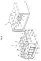
- Fig. 1 shows a pair of connectors that are a male connector 1 and a female connector 2 to be fitted thereon, with each connector having an interlocking structure of the present invention.
- the connectors 1 and 2 respectively comprise housings 3 and 4 that are made of an insulating resin such as Nylon (a registered trademark).
- the housing 3 of the male connector 1 (hereinafter referred to as a first connector housing) is generally a parallelepiped box having an open front face. A plurality of post contacts 6 penetrating a bottom 5 (see Fig. 5) of the first connector housing are secured therein.
- the first connector housing 3 has, on its outer surface, a slope 8 slanted forwards and downwards and a shoulder 9 vertically extending downwards from a rear end of the slope.
- the slope 8 and the shoulder 9 define together a generally upright lockable lug 7.
- a guiding projection 10 for positioning the male connector in correct place continues forwards from a frontal face of the lockable lug 7.
- the female connector 2 comprises the housing 4 (hereinafter referred to as a second connector housing) is also a parallelepiped fittable on the first connector housing 3.
- the housing 4 has a plurality of compartments 13 penetrating it and corresponding to the male connector's 1 post contacts 6 so as to receive socket contacts 12. Those socket contacts will have been crimped on respective wire ends 11 as shown in Fig. 5.
- a flat lock arm 15 is formed with a hook-shaped pawl 16 that is disposed at a free end of said arm so as to engage with the lockable lug 7 of the first connector housing 3.
- Two elastically deformable hinge-shaped feet 17 see Figs.
- a push lever 18 protruding upwards is additionally formed at a rear end of the lock arm 15 that extends backwards beyond the hinge-shaped feet 17.
- the push lever 18 is intended to be pressed down by the operator with his or her finger or fingers so that the lock arm 15 will pivot on the hinge-shaped feet 17.
- both the lateral ends of the push lever 18 are firmly adjoined a pair of elastically deformable bridging members 19 that are integral with and continue from the respective side walls of the second connector housing 4.
- the bridging members 19 extend sideways and outwards at first from the respective ends of the push lever 18, and then curve downwards to be integral with the side walls of the second connector housing 4.
- the push lever 18 and the bridging members 19 do form an arch-shaped lock guard above the rear end of the second housing 4.
- a loop is defined by and along the push lever 18, the body of the second housing 4 and the pair of the bridging members 19, so as to serve as a guard for said lever 18.
- Disposed below the push lever 18 is a guide groove 20 facing and engageable with the guiding projection 10, so that the latter of the first housing 3 can take a correct position in the second housing 4.
- Fig. 5 shows the connectors of the described structure and their positions in use.
- the second connector housing 4 of the female connector 2 having their socket contacts 12 crimped on wire ends 11 will be coupled with the first connector housing 3 of the male connector 1 surface-mounted on a printed circuit board 21. Consequently, each post contact 6 will fit in the socket contact 12 to be electrically connected to each other, with the pawl 16 of the lock arm 15 simultaneously engaging with the lockable lug 7 of the first housing 3 to thereby interlock the connector housings 3 and 4 with each other.
- the guiding projection 10 of the first housing 3 will be set in place thanks to its engagement with the guide groove 20, before pawl 16 of the lock arm 15 moves along the slope 8 of the lockable lug 7 and consequently the arm 15 pivots outwards on the hinge-shaped feet 17.
- Such an outward pivoting of the lock arm 15 will allow the pawl 16 to slide over the slope 8, causing elastic recovery of the arm 15 to bring the shoulder 9 of the lug 7 into a normally non-releasable engagement with the pawl 16.
- the housing 4 of the female connector 2 may be disengaged from the connector housing 3 of the male connector 1, if necessary after or during use of the electronic or electric device.
- the user or operator need to just press the push lever 18 to elastically deform the bridging members 19 so as to swing the lock arm 15 outwards a little around the hinge-shaped feet 17.
- the pawl 16 will be freed from the lockable lug 7 to make it possible to unlock and pull the second connector housing 4 out of the first connector housing 3.
- the lock arm in the embodiment described above is held in place by the elastically deformable hinge-shaped feet and the pair of elastically deformable bridging members.
- the bridging members are disposed respectively on and continue from the opposite lateral ends of the push lever, which lever in turn is formed as the rear end portion of the lock arm.
- the hinge-shaped feet and the bridging members are designed to be of a proper bending strength (elasticity) to raise rigidity of the push lever to such a degree that the connectors can still be engaged with and disengaged from each other.
- the bridging members having their one ends connected to lateral sides of the push lever do have their other ends made integral with the side walls of the housing body.
- the arch-shaped lock guard thus formed above the rear end of said housing body thus provides a loop extending through the push lever and the housing body. This loop will not only guard the push lever but also will prevent the wires in another harness from catching and/or moving the lever to unintentionally release the lock arm.
Landscapes
- Details Of Connecting Devices For Male And Female Coupling (AREA)
Abstract
Description
Claims (2)
- A structure for interlocking connectors with each other, the connectors being a male connector and a female connector to be fitted thereon, the structure comprising:a housing of one of the connectors;a lockable lug formed on an outer surface of the one connector;a housing of the other connector;a lock arm integral with a pawl corresponding to and engageable with the lockable lug, the lock arm being formed on an outer surface of the other connector housing;a pair of elastically deformable hinge-shaped feet each having one end integral with the other connector housing and another end continuing from the lock arm; anda push lever having lateral ends formed integral with a rear end of the lock arm extending rearwardly beyond the hinge-shaped feet,the structure further comprising:
a pair of bridging members that continue from opposite side walls of the other connector housing so as to be integral with the lateral ends of the push lever such that an arch-shaped lock guard portion is provided above the other connector housing. - A structure for interlocking connectors as defined in claim 1, wherein each bridging member is of a curved shape.
Applications Claiming Priority (2)
| Application Number | Priority Date | Filing Date | Title |
|---|---|---|---|
| JP2000068123A JP3405954B2 (en) | 2000-03-13 | 2000-03-13 | Connector lock structure |
| JP2000068123 | 2000-03-13 |
Publications (2)
| Publication Number | Publication Date |
|---|---|
| EP1134852A1 true EP1134852A1 (en) | 2001-09-19 |
| EP1134852B1 EP1134852B1 (en) | 2003-06-04 |
Family
ID=18587222
Family Applications (1)
| Application Number | Title | Priority Date | Filing Date |
|---|---|---|---|
| EP01301880A Expired - Lifetime EP1134852B1 (en) | 2000-03-13 | 2001-03-01 | Structure for interlocking connectors |
Country Status (8)
| Country | Link |
|---|---|
| US (1) | US6383011B2 (en) |
| EP (1) | EP1134852B1 (en) |
| JP (1) | JP3405954B2 (en) |
| KR (1) | KR100673281B1 (en) |
| CN (1) | CN100428577C (en) |
| DE (1) | DE60100320T2 (en) |
| HK (1) | HK1043667A1 (en) |
| TW (1) | TW488117B (en) |
Cited By (2)
| Publication number | Priority date | Publication date | Assignee | Title |
|---|---|---|---|---|
| WO2012119899A1 (en) * | 2011-03-10 | 2012-09-13 | Tyco Electronics Amp Gmbh | Connector housing for a connector as well as connector or connecting device |
| USD1013642S1 (en) * | 2021-01-13 | 2024-02-06 | J.S.T. Corporation | Connector |
Families Citing this family (63)
| Publication number | Priority date | Publication date | Assignee | Title |
|---|---|---|---|---|
| USD463776S1 (en) | 2000-03-24 | 2002-10-01 | J.S.T. Mfg. Co., Ltd. | Connector housing |
| USD463370S1 (en) | 2000-03-24 | 2002-09-24 | J.S.T. Mfg. Co., Ltd. | Connector housing |
| USD464321S1 (en) | 2000-06-19 | 2002-10-15 | J.S.T. Mfg. Co., Ltd. | Connector for printed circuit boards |
| USD464625S1 (en) | 2000-06-19 | 2002-10-22 | J.S.T. Mfg. Co., Ltd. | Connector for printed circuit boards |
| JP2002107571A (en) * | 2000-09-27 | 2002-04-10 | Furukawa Electric Co Ltd:The | Optical connector |
| USD459704S1 (en) | 2001-02-14 | 2002-07-02 | J.S.T. Mfg. Co., Ltd. | Connector housing |
| JP2002252063A (en) * | 2001-02-26 | 2002-09-06 | Jst Mfg Co Ltd | Connector assembly with locking mechanism |
| USD463375S1 (en) | 2001-05-17 | 2002-09-24 | J.S.T. Mfg. Co., Ltd. | Connector for printed circuit boards |
| USD479197S1 (en) | 2002-04-04 | 2003-09-02 | Hon Hai Precision Ind. Co., Ltd. | Electrical connector |
| USD478048S1 (en) | 2002-05-31 | 2003-08-05 | Lyall Assemblies, Inc. | Waterproof plug |
| USD478049S1 (en) | 2002-07-12 | 2003-08-05 | Lyall Technologies, Inc. | Waterproof plug |
| US6638096B1 (en) * | 2002-08-23 | 2003-10-28 | Hon Hai Precision Ind. Co., Ltd. | Electrical connector having improved latching mechanism |
| EP1496068A1 (en) * | 2003-07-09 | 2005-01-12 | Total Petrochemicals Research Feluy | Process to produce bimodal polyolefins with metallocene catalysts using two reaction zones. |
| JP4062250B2 (en) * | 2003-12-22 | 2008-03-19 | 住友電装株式会社 | connector |
| US20050170586A1 (en) * | 2004-01-29 | 2005-08-04 | O2Ic, Inc., (A California Corporation) | Method of manufacturing non-volatile DRAM |
| USD524753S1 (en) * | 2004-10-27 | 2006-07-11 | Molex Incorporated | Electric connector |
| USD524754S1 (en) * | 2004-10-27 | 2006-07-11 | Molex Incorporated | Low profile electric connector |
| JP4479474B2 (en) * | 2004-11-12 | 2010-06-09 | 住友電装株式会社 | connector |
| US6945807B1 (en) * | 2004-11-15 | 2005-09-20 | Hon Hai Precision Ind. Co., Ltd. | Cable end connector having integral latch means |
| JP4701741B2 (en) * | 2005-02-21 | 2011-06-15 | パナソニック株式会社 | Electrical equipment protection device |
| TWM281310U (en) * | 2005-04-01 | 2005-11-21 | Molex Taiwan Ltd | Electrical connector |
| US8072834B2 (en) | 2005-08-25 | 2011-12-06 | Cypress Semiconductor Corporation | Line driver circuit and method with standby mode of operation |
| JP4755056B2 (en) * | 2006-09-15 | 2011-08-24 | 日本圧着端子製造株式会社 | connector |
| US8109883B2 (en) | 2006-09-28 | 2012-02-07 | Tyco Healthcare Group Lp | Cable monitoring apparatus |
| US8668651B2 (en) | 2006-12-05 | 2014-03-11 | Covidien Lp | ECG lead set and ECG adapter system |
| JP4903599B2 (en) * | 2007-02-21 | 2012-03-28 | 株式会社ニフコ | Locking structure of electrical connection device |
| DE202007005300U1 (en) * | 2007-04-11 | 2008-08-21 | Weidmüller Interface GmbH & Co. KG | Connectors, in particular for printed circuit boards |
| KR100858729B1 (en) | 2007-06-27 | 2008-09-17 | 한국단자공업 주식회사 | Connector housing |
| US7632131B2 (en) * | 2007-10-16 | 2009-12-15 | T-Conn Precision Corporation | Structure of electronic connector |
| CA2646037C (en) | 2007-12-11 | 2017-11-28 | Tyco Healthcare Group Lp | Ecg electrode connector |
| TWD130466S1 (en) * | 2008-05-06 | 2009-08-21 | 太谷電子恩普股份有限公司 | Electrical connector |
| USD604248S1 (en) * | 2008-05-16 | 2009-11-17 | Tyco Electronics Amp K.K. | Electrical connector |
| USD737979S1 (en) | 2008-12-09 | 2015-09-01 | Covidien Lp | ECG electrode connector |
| US8694080B2 (en) | 2009-10-21 | 2014-04-08 | Covidien Lp | ECG lead system |
| KR200453511Y1 (en) | 2009-12-29 | 2011-05-13 | 한국강성(주) | Micro usb connector plug |
| CA2746944C (en) | 2010-07-29 | 2018-09-25 | Tyco Healthcare Group Lp | Ecg adapter system and method |
| US8210864B1 (en) * | 2011-03-25 | 2012-07-03 | Delphi Technologies, Inc. | Connector terminal position assurance device |
| DK2734106T3 (en) | 2011-07-22 | 2020-01-06 | Kpr Us Llc | ECG electrode connector |
| JP2013077440A (en) * | 2011-09-30 | 2013-04-25 | Jst Mfg Co Ltd | Electric connector with lock mechanism |
| US8634901B2 (en) | 2011-09-30 | 2014-01-21 | Covidien Lp | ECG leadwire system with noise suppression and related methods |
| JP5798897B2 (en) | 2011-11-24 | 2015-10-21 | 矢崎総業株式会社 | Lever fitting type connector |
| DE102012025107A1 (en) * | 2012-12-21 | 2014-06-26 | Erni Production Gmbh & Co. Kg | The connector assembly |
| USD771818S1 (en) | 2013-03-15 | 2016-11-15 | Covidien Lp | ECG electrode connector |
| US9408546B2 (en) | 2013-03-15 | 2016-08-09 | Covidien Lp | Radiolucent ECG electrode system |
| WO2014149548A1 (en) | 2013-03-15 | 2014-09-25 | Covidien Lp | Electrode connector with a conductive member |
| USD745459S1 (en) * | 2013-06-17 | 2015-12-15 | Wago Verwaltungsgesellschaft Mbh | Electrical plug-in connector |
| US9048576B2 (en) * | 2013-08-02 | 2015-06-02 | GM Global Technology Operations LLC | Multiple-stage interlocking electrical connector with locking assurance mechanism |
| US9960563B2 (en) | 2014-06-30 | 2018-05-01 | Emerson Electric Co. | Connecting electrical equipment through wiring harnesses |
| US10249414B2 (en) * | 2014-06-30 | 2019-04-02 | Emerson Electric Co. | Connecting electrical equipment through wiring harnesses |
| JP6249297B2 (en) * | 2014-11-04 | 2017-12-20 | 住友電装株式会社 | connector |
| JP5920504B1 (en) * | 2015-02-19 | 2016-05-18 | 第一精工株式会社 | Electrical connector |
| JP6367746B2 (en) * | 2015-03-30 | 2018-08-01 | 日本圧着端子製造株式会社 | Connector and electrical connection device |
| US20170222361A1 (en) * | 2016-02-01 | 2017-08-03 | Ford Global Technologies, Llc | Electrical connection system |
| CN107172837B (en) * | 2016-03-08 | 2024-02-20 | 泰科电子(上海)有限公司 | Electronic device mounting bases, electronic device mounting base assemblies, electrical appliance stands and electrical box assemblies |
| JP6609210B2 (en) * | 2016-03-25 | 2019-11-20 | 日本圧着端子製造株式会社 | Connector with locking mechanism |
| DE102016120063B4 (en) * | 2016-10-20 | 2018-07-19 | Rosenberger Hochfrequenztechnik Gmbh & Co. Kg | connector |
| CN111262077B (en) * | 2017-06-23 | 2022-01-14 | 上海莫仕连接器有限公司 | Power supply connector |
| JP1597125S (en) * | 2017-07-20 | 2018-02-13 | ||
| JP2019140046A (en) * | 2018-02-15 | 2019-08-22 | 住友電装株式会社 | Connector, connector device |
| KR102234247B1 (en) * | 2018-08-29 | 2021-04-02 | 앱티브 테크놀러지스 리미티드 | Connector and connector assembly comprising the same |
| JP7032467B2 (en) * | 2020-03-09 | 2022-03-08 | 矢崎総業株式会社 | Connector lock structure |
| CN113193412B (en) * | 2021-05-18 | 2023-12-01 | 菲尼克斯亚太电气(南京)有限公司 | Connector outer shell |
| USD1101687S1 (en) * | 2022-09-28 | 2025-11-11 | Delta Electronics (Shanghai) Co., Ltd. | Electrical connector |
Citations (4)
| Publication number | Priority date | Publication date | Assignee | Title |
|---|---|---|---|---|
| US4448467A (en) * | 1982-09-02 | 1984-05-15 | Amp Incorporated | Connector assembly having compact keying and latching system |
| EP0757411A2 (en) * | 1995-08-03 | 1997-02-05 | Sumitomo Wiring Systems, Ltd. | Connector |
| EP0820121A1 (en) * | 1996-07-15 | 1998-01-21 | Sumitomo Wiring Systems, Ltd. | Connector cover |
| WO1999035717A1 (en) * | 1998-01-09 | 1999-07-15 | Framatome Connectors International S.A. | Electric connector |
Family Cites Families (18)
| Publication number | Priority date | Publication date | Assignee | Title |
|---|---|---|---|---|
| JPS563900Y2 (en) * | 1978-09-29 | 1981-01-28 | ||
| JPH0447908Y2 (en) * | 1984-09-25 | 1992-11-11 | ||
| JPS6163782U (en) * | 1984-10-01 | 1986-04-30 | ||
| JPH0638378Y2 (en) * | 1987-09-30 | 1994-10-05 | 矢崎総業株式会社 | connector |
| JPH01112579U (en) * | 1988-01-25 | 1989-07-28 | ||
| US4986766A (en) * | 1988-08-17 | 1991-01-22 | Molex Incorporated | Electrical connector having anti-overstress latch |
| JPH03208275A (en) * | 1990-01-08 | 1991-09-11 | Sumitomo Wiring Syst Ltd | Detecting method of fitting lock of connector and connector using such detecting method |
| JPH04220972A (en) * | 1990-12-21 | 1992-08-11 | Kansei Corp | Locking device for electric connector |
| JP2506098Y2 (en) * | 1991-02-12 | 1996-08-07 | 矢崎総業株式会社 | Male connector |
| JP2904380B2 (en) * | 1992-09-09 | 1999-06-14 | 矢崎総業株式会社 | connector |
| JP2593281Y2 (en) * | 1992-10-06 | 1999-04-05 | 住友電装株式会社 | connector |
| GB2308755B (en) * | 1995-12-28 | 1997-12-17 | Yazaki Corp | Half-fitting prevention connector |
| JP3458034B2 (en) * | 1995-12-28 | 2003-10-20 | 矢崎総業株式会社 | Connector mating release mechanism |
| JPH10112356A (en) * | 1996-10-07 | 1998-04-28 | Yazaki Corp | Half mating prevention connector |
| JP3235489B2 (en) * | 1996-11-14 | 2001-12-04 | 住友電装株式会社 | Block connector |
| US5910027A (en) * | 1997-10-08 | 1999-06-08 | Ut Automotive Dearborn, Inc. | Connector position assurance |
| JPH11121089A (en) * | 1997-10-20 | 1999-04-30 | Sumitomo Wiring Syst Ltd | Connector |
| JP3415008B2 (en) * | 1997-11-12 | 2003-06-09 | 住友電装株式会社 | connector |
-
2000
- 2000-03-13 JP JP2000068123A patent/JP3405954B2/en not_active Expired - Fee Related
-
2001
- 2001-02-15 TW TW090103459A patent/TW488117B/en not_active IP Right Cessation
- 2001-02-26 US US09/791,829 patent/US6383011B2/en not_active Expired - Lifetime
- 2001-03-01 EP EP01301880A patent/EP1134852B1/en not_active Expired - Lifetime
- 2001-03-01 DE DE60100320T patent/DE60100320T2/en not_active Expired - Lifetime
- 2001-03-08 CN CNB011094451A patent/CN100428577C/en not_active Expired - Fee Related
- 2001-03-12 KR KR1020010012548A patent/KR100673281B1/en not_active Expired - Lifetime
-
2002
- 2002-04-30 HK HK02103262.3A patent/HK1043667A1/en unknown
Patent Citations (4)
| Publication number | Priority date | Publication date | Assignee | Title |
|---|---|---|---|---|
| US4448467A (en) * | 1982-09-02 | 1984-05-15 | Amp Incorporated | Connector assembly having compact keying and latching system |
| EP0757411A2 (en) * | 1995-08-03 | 1997-02-05 | Sumitomo Wiring Systems, Ltd. | Connector |
| EP0820121A1 (en) * | 1996-07-15 | 1998-01-21 | Sumitomo Wiring Systems, Ltd. | Connector cover |
| WO1999035717A1 (en) * | 1998-01-09 | 1999-07-15 | Framatome Connectors International S.A. | Electric connector |
Cited By (3)
| Publication number | Priority date | Publication date | Assignee | Title |
|---|---|---|---|---|
| WO2012119899A1 (en) * | 2011-03-10 | 2012-09-13 | Tyco Electronics Amp Gmbh | Connector housing for a connector as well as connector or connecting device |
| USD1013642S1 (en) * | 2021-01-13 | 2024-02-06 | J.S.T. Corporation | Connector |
| USD1044738S1 (en) * | 2021-01-13 | 2024-10-01 | J.S.T. Corporation | Connector |
Also Published As
| Publication number | Publication date |
|---|---|
| US6383011B2 (en) | 2002-05-07 |
| TW488117B (en) | 2002-05-21 |
| DE60100320T2 (en) | 2004-05-13 |
| CN1319922A (en) | 2001-10-31 |
| KR20010091972A (en) | 2001-10-23 |
| KR100673281B1 (en) | 2007-01-24 |
| CN100428577C (en) | 2008-10-22 |
| DE60100320D1 (en) | 2003-07-10 |
| EP1134852B1 (en) | 2003-06-04 |
| HK1043667A1 (en) | 2002-09-20 |
| JP2001257032A (en) | 2001-09-21 |
| JP3405954B2 (en) | 2003-05-12 |
| US20010021603A1 (en) | 2001-09-13 |
Similar Documents
| Publication | Publication Date | Title |
|---|---|---|
| US6383011B2 (en) | Structure for interlocking connectors | |
| EP1215772B1 (en) | Connector assembly having an interlocking system | |
| EP1235308B1 (en) | Connector assembly having a latching mechanism | |
| EP1587178B1 (en) | A connector | |
| JP4162214B2 (en) | Electrical connector assembly | |
| WO2004114471A1 (en) | Electrical connector | |
| WO2016042523A1 (en) | Electrical connector and electrical connector assembly | |
| US20040102104A1 (en) | Electric connector | |
| CN101116227A (en) | Plug connectors with mating protection and alignment | |
| EP1548894B1 (en) | A connector | |
| JP2965498B2 (en) | Electrical connector assembly | |
| CN102005669A (en) | Electric line connector | |
| JP2004220824A (en) | Electric connector | |
| JP2004095346A (en) | Connector assembly and connector for use with the same | |
| JP4359414B2 (en) | Connector lock structure | |
| JP2004047352A (en) | Electrical connector with locking mechanism | |
| KR200318477Y1 (en) | Connector assembly for cars coupling as one body a number of pin | |
| JPH0467582A (en) | Low insertion/extraction force electrical connectors | |
| JP7221807B2 (en) | housing | |
| KR101076153B1 (en) | Connector having an interlocking system | |
| JP3999535B2 (en) | Electrical connector | |
| US20040224555A1 (en) | Automotive flatwire connector | |
| KR101193324B1 (en) | Electrical connector latch | |
| KR200318476Y1 (en) | Coupling guide structure of connector assembly for cars | |
| JP3679161B2 (en) | connector |
Legal Events
| Date | Code | Title | Description |
|---|---|---|---|
| PUAI | Public reference made under article 153(3) epc to a published international application that has entered the european phase |
Free format text: ORIGINAL CODE: 0009012 |
|
| AK | Designated contracting states |
Kind code of ref document: A1 Designated state(s): DE FR GB IT SE Kind code of ref document: A1 Designated state(s): AT BE CH CY DE DK ES FI FR GB GR IE IT LI LU MC NL PT SE TR |
|
| AX | Request for extension of the european patent |
Free format text: AL;LT;LV;MK;RO;SI |
|
| 17P | Request for examination filed |
Effective date: 20020104 |
|
| AKX | Designation fees paid |
Free format text: DE FR GB IT SE |
|
| 17Q | First examination report despatched |
Effective date: 20020426 |
|
| GRAH | Despatch of communication of intention to grant a patent |
Free format text: ORIGINAL CODE: EPIDOS IGRA |
|
| GRAH | Despatch of communication of intention to grant a patent |
Free format text: ORIGINAL CODE: EPIDOS IGRA |
|
| GRAA | (expected) grant |
Free format text: ORIGINAL CODE: 0009210 |
|
| AK | Designated contracting states |
Designated state(s): DE FR GB IT SE |
|
| REG | Reference to a national code |
Ref country code: GB Ref legal event code: FG4D |
|
| REF | Corresponds to: |
Ref document number: 60100320 Country of ref document: DE Date of ref document: 20030710 Kind code of ref document: P |
|
| REG | Reference to a national code |
Ref country code: SE Ref legal event code: TRGR |
|
| ET | Fr: translation filed | ||
| PLBE | No opposition filed within time limit |
Free format text: ORIGINAL CODE: 0009261 |
|
| STAA | Information on the status of an ep patent application or granted ep patent |
Free format text: STATUS: NO OPPOSITION FILED WITHIN TIME LIMIT |
|
| 26N | No opposition filed |
Effective date: 20040305 |
|
| PGFP | Annual fee paid to national office [announced via postgrant information from national office to epo] |
Ref country code: SE Payment date: 20070319 Year of fee payment: 7 |
|
| PGFP | Annual fee paid to national office [announced via postgrant information from national office to epo] |
Ref country code: IT Payment date: 20070605 Year of fee payment: 7 |
|
| EUG | Se: european patent has lapsed | ||
| PG25 | Lapsed in a contracting state [announced via postgrant information from national office to epo] |
Ref country code: SE Free format text: LAPSE BECAUSE OF NON-PAYMENT OF DUE FEES Effective date: 20080302 |
|
| PG25 | Lapsed in a contracting state [announced via postgrant information from national office to epo] |
Ref country code: IT Free format text: LAPSE BECAUSE OF NON-PAYMENT OF DUE FEES Effective date: 20080301 |
|
| REG | Reference to a national code |
Ref country code: DE Ref legal event code: R119 Ref document number: 60100320 Country of ref document: DE Ref country code: DE Ref legal event code: R409 Ref document number: 60100320 Country of ref document: DE |
|
| REG | Reference to a national code |
Ref country code: DE Ref legal event code: R409 Ref document number: 60100320 Country of ref document: DE |
|
| PGFP | Annual fee paid to national office [announced via postgrant information from national office to epo] |
Ref country code: DE Payment date: 20130227 Year of fee payment: 13 Ref country code: GB Payment date: 20130215 Year of fee payment: 13 Ref country code: FR Payment date: 20130325 Year of fee payment: 13 |
|
| REG | Reference to a national code |
Ref country code: DE Ref legal event code: R119 Ref document number: 60100320 Country of ref document: DE |
|
| GBPC | Gb: european patent ceased through non-payment of renewal fee |
Effective date: 20140301 |
|
| REG | Reference to a national code |
Ref country code: FR Ref legal event code: ST Effective date: 20141128 |
|
| REG | Reference to a national code |
Ref country code: DE Ref legal event code: R119 Ref document number: 60100320 Country of ref document: DE Effective date: 20141001 Ref country code: DE Ref legal event code: R119 Ref document number: 60100320 Country of ref document: DE Effective date: 20111001 |
|
| PG25 | Lapsed in a contracting state [announced via postgrant information from national office to epo] |
Ref country code: GB Free format text: LAPSE BECAUSE OF NON-PAYMENT OF DUE FEES Effective date: 20140301 Ref country code: DE Free format text: LAPSE BECAUSE OF NON-PAYMENT OF DUE FEES Effective date: 20141001 Ref country code: FR Free format text: LAPSE BECAUSE OF NON-PAYMENT OF DUE FEES Effective date: 20140331 |