EP1134567B1 - Non contacting torque sensor - Google Patents
Non contacting torque sensor Download PDFInfo
- Publication number
- EP1134567B1 EP1134567B1 EP01302388A EP01302388A EP1134567B1 EP 1134567 B1 EP1134567 B1 EP 1134567B1 EP 01302388 A EP01302388 A EP 01302388A EP 01302388 A EP01302388 A EP 01302388A EP 1134567 B1 EP1134567 B1 EP 1134567B1
- Authority
- EP
- European Patent Office
- Prior art keywords
- disks
- shaft
- disk
- coupler
- signals
- Prior art date
- Legal status (The legal status is an assumption and is not a legal conclusion. Google has not performed a legal analysis and makes no representation as to the accuracy of the status listed.)
- Expired - Lifetime
Links
- 238000006073 displacement reaction Methods 0.000 claims description 8
- 230000010363 phase shift Effects 0.000 claims description 7
- 230000002238 attenuated effect Effects 0.000 claims description 2
- 239000011810 insulating material Substances 0.000 claims description 2
- 230000007423 decrease Effects 0.000 claims 1
- 238000005259 measurement Methods 0.000 description 4
- 238000000034 method Methods 0.000 description 3
- 238000010586 diagram Methods 0.000 description 2
- 230000003287 optical effect Effects 0.000 description 2
- 238000004378 air conditioning Methods 0.000 description 1
- 239000013078 crystal Substances 0.000 description 1
- 230000001939 inductive effect Effects 0.000 description 1
- 230000007704 transition Effects 0.000 description 1
Images


Classifications
-
- G—PHYSICS
- G01—MEASURING; TESTING
- G01L—MEASURING FORCE, STRESS, TORQUE, WORK, MECHANICAL POWER, MECHANICAL EFFICIENCY, OR FLUID PRESSURE
- G01L3/00—Measuring torque, work, mechanical power, or mechanical efficiency, in general
- G01L3/02—Rotary-transmission dynamometers
- G01L3/04—Rotary-transmission dynamometers wherein the torque-transmitting element comprises a torsionally-flexible shaft
- G01L3/10—Rotary-transmission dynamometers wherein the torque-transmitting element comprises a torsionally-flexible shaft involving electric or magnetic means for indicating
- G01L3/101—Rotary-transmission dynamometers wherein the torque-transmitting element comprises a torsionally-flexible shaft involving electric or magnetic means for indicating involving magnetic or electromagnetic means
- G01L3/105—Rotary-transmission dynamometers wherein the torque-transmitting element comprises a torsionally-flexible shaft involving electric or magnetic means for indicating involving magnetic or electromagnetic means involving inductive means
-
- G—PHYSICS
- G01—MEASURING; TESTING
- G01L—MEASURING FORCE, STRESS, TORQUE, WORK, MECHANICAL POWER, MECHANICAL EFFICIENCY, OR FLUID PRESSURE
- G01L3/00—Measuring torque, work, mechanical power, or mechanical efficiency, in general
- G01L3/02—Rotary-transmission dynamometers
- G01L3/04—Rotary-transmission dynamometers wherein the torque-transmitting element comprises a torsionally-flexible shaft
- G01L3/10—Rotary-transmission dynamometers wherein the torque-transmitting element comprises a torsionally-flexible shaft involving electric or magnetic means for indicating
- G01L3/109—Rotary-transmission dynamometers wherein the torque-transmitting element comprises a torsionally-flexible shaft involving electric or magnetic means for indicating involving measuring phase difference of two signals or pulse trains
Definitions
- the present invention is directed to a non contacting torque sensor and specifically for a sensor that is especially useful for the steering columns of automobiles and other vehicles.
- US 4,680,976 describes a torque sensor for detecting the relative angular position of a shaft by using overlapping disks that transmit and receive high frequency signals.
- US 4,875,379 describes a device for measuring the torque on a shaft using pulsed beams of light passing through measuring disks and light detectors.
- the axis 10 includes the shaft 11 divided into a first portion 11a and a second portion 11b connected by a torsion bar 12.
- the shaft in the preferred embodiment would be driven by a nominally represented steering wheel 13.
- a coupler disk C2 mounted on shaft portion 11a.
- a coupler disk C 1 and also C' are mounted on shaft portion 11b. All of these are represented as coupler disk C illustrated in Figure 3.
- It is a disk made of insulating material such as plastic and includes a crescent-shaped symmetrical conductive pattern 14. The pattern and its use is discussed in the above co-pending patent application. All of the coupler disks are essentially identical.
- coupler disk C' is coupled to shaft portion 11b with a reduction gear (not specifically shown) with a 1:5 gear reduction.
- this gear reduction provides for a effective rotation of less than 360°.
- the output of this portion of the sensor that is C', TX' and RX' provides a measure of the angular rotation of the shaft in accordance with the above-mentioned patent application.
- a base 15 Fixed to a base 15, also in the form of an annular disk in relation to shafts 1 la and 11b are transmit and receive disks RX1, RX2, TX, RX1' and TX'. All are illustrated in Figure 2. All of the disks consist of six spiral loop antenna patterns designated 1 through 6 which are segmentally arranged in a circular pattern around the disk and circling the disk for a full 360°. Thus each coil in the form of a spiral loop antenna has been deformed to provide a 60° segment. The above patent application describes this in greater detail.
- Figure 5 is a circuit diagram indicating how the receiver and transmit coils on disks RX and TX, the respective coils being labeled T1-T6, R1-R6 are inductively coupled to each other. This inductance is attenuated by either the couplers C1 or C2 or C'.
- An oscillator or signal source 17 supplies a signal, F c , to the coils of the transmit disk TX. Since the coupler disk will interrupt and attenuate the signal amplitudes based on the coupler pattern with respect to the position of each receiver coil, six different amplitude signals are simultaneously generated at any one angular position of the coupler.
- Figure 4 illustrates this in complete detail, which shows the various receivers, transmitters and couplers RX, TX and C. These are driven in a manner as in Figure 5, by a 1Mhz crystal oscillator 17 which drives a digital wave form generator 41. It's six output lines designated L01-L06 provide the six local oscillator signals which are shifted in phase from one another by 60°. These drive the six mixers 16 which are summed at summing amplifier A1.
- a low pass filter amplifier A2 drives a comparator A3 which turns the sinusoidal wave into a square wave X2 to drive a pulse width modulating generator 43 to provide on output line 44 a pulse width modulated (PWM) angular position output signal.
- PWM pulse width modulated
- the PWM angular position signal results. This is all discussed in the above pending patent application where the PWM generator is an RS flip flop.
- An analog output is also derived from a filter 46. This is all from the X2 output side from the RX2 receive disk.
- RX1 receive disk there is a similar mixer unit 16', low pass filter A2' and comparator A3' to produce an X1 square wave related to the position of the shaft.
- the X2 square wave is shifted 90° by a 90° phase shifter 52, both for preventing cross-over ambiguity at a 0° rotational position (where one coupler may be at 355° and the other at +5°) and at the same time to provide a simplified computational technique for clockwise and counter-clockwise (right and left) torque on the steering wheel.
- a 90° shift is preferred, but some other phase shift would work equally as well, for example 60°.
- the angular comparator51 is illustrated in Figure 7 as an exclusive OR gate with the X1 and X2 inputs and operating in a manner so that only when there is a differential input is there an output, which is typical of exclusive OR gates.
- the output of this OR gate is filtered at 53 to provide a analog torque signal which may drive, for example, the electric steering motor of an automobile or other appropriate actuator device.
- the torque signal is provided by and is proportional to the differential phase shift between X1 and X2. This is, of course, as discussed above a measure of the angular differential displacement of the two portions of the shaft.
- the digital waveform generator 41 of Figure 4 is shown in greater detail in Figure 6 where a divide by M Unit 48 provides 60° phase shifted signals F m which drive the respective mixers 47a-47f which also have the F c signal source as input to provide the final output signals.
- Figure 8 illustrates the operation of the invention by a characteristic curve where at 0 torque the X1 and X2 signals are exactly phase shifted 90° (by 90° phase shifter 52) to produce an output waveform having a 50% duty cycle at zero torque. If the phase shift were different, for example 60°, then this would be a slightly different duty cycle. However, it is believed that the 90° phase shift providing the 50% duty cycle aptly and simply allows the electrical circuitry to provide a left and right torque in an efficient manner. In other words, the 90° phase shift causes the signal X1 to fall in the center of X2 at zero torque.
- the associated waveforms show that the X2 square wave is shifted toward X1 from 50% down to 0%, the proportion of the shift or that duty cycle is indicated by the waveform T 1, as 30% (for example) to provide a linear indication of torque.
- the T2 curve is the result of the leading or lagging of X2 relative to X1 where the duty cycle is shown as 70% but may vary, of course, from 50% to 100% in a linear manner to illustrate the left-handed or counter-clockwise torque.
- the duty cycle or torque signal varies in a manner proportionate to the lead or lag of the two couplers.
- a typical differential angular displacement range of a drive shaft is ⁇ 8° to ⁇ 12°.
- the X1 and X2 signals would never cross over at the 180° point. Since the two receiver units RX1 and RX2 share the common transmitter, TX, there is very little error in the measurement process.
- a 1 Cos ⁇ o t is the received signal indicative of the rotational component and [ Cos ⁇ a - Cos ⁇ b ] is the torque component.
- the present invention provides a true non contacting differential angular displacement (torque) measurement.
Landscapes
- Physics & Mathematics (AREA)
- General Physics & Mathematics (AREA)
- Electromagnetism (AREA)
- Measurement Of Length, Angles, Or The Like Using Electric Or Magnetic Means (AREA)
- Power Steering Mechanism (AREA)
- Force Measurement Appropriate To Specific Purposes (AREA)
- Steering Controls (AREA)
Description
- The present invention is directed to a non contacting torque sensor and specifically for a sensor that is especially useful for the steering columns of automobiles and other vehicles.
- The never-ending demand for higher efficiency and higher reliability in automobiles, and the advent of the electrical vehicle (EV), have collectively doomed power hungry devices such as the Power Steering Hydraulic Pump and the Air Conditioning compressor. The best replacement for the Hydraulic Pump at this time is an electric motor to directly assist the steering effort. The problem now lies with reliably sensing the driver-applied torque so as to know how much steering assist to add. This could be accomplished with potentiometers, but the limited life of the contacting wipers is unacceptable in this very critical application. Another possibility is the use of optical encoders. While this would also perform the function, it is prohibitively expensive (especially absolute optical encoders), and the use of the light source is discouraged due to reliability considerations.
- There is already known a device for sensing angular position or rotation of a steering column, as disclosed in
co-pending application EP 1 083 408 A2 entitled Angular Position Sensor With Inductive Attenuating Coupler assigned to the present assignee. - US 4,680,976 describes a torque sensor for detecting the relative angular position of a shaft by using overlapping disks that transmit and receive high frequency signals.
- US 4,875,379 describes a device for measuring the torque on a shaft using pulsed beams of light passing through measuring disks and light detectors.
- US 4,513,628 describes a torque detector which detects the deformation of a spring by using electromagnetic pick-ups.
- It is a general object of the present invention to provide an improved torque sensor and one of the non contacting type.
- In accordance with the above invention there is provided a non-contacting torque sensor as described in
Claim 1. -
- Figure 1 is a side elevation view of a sensor incorporating the present invention.
- Figure 2 is a plan view of portions of Figure 1.
- Figure 3 is a plan view of another portion of Figure 1.
- Figures 4 is a simplified circuit schematic incorporating Figures 1, 2 and 3 illustrating the present invention..
- Figure 5 is a more detailed schematic of a portion of Figure 4.
- Figure 6 is a more detailed circuit schematic of a portion of Figure 4.
- Figures 7 is a circuit schematic of an OR gate of Figure 7 along with an explanatory table.
- Figure 8 is a characteristic curve along with explanatory timing diagram wave forms illustrating the operation of the present invention.
- Referring now to Figure 1 the
axis 10 includes the shaft 11 divided into afirst portion 11a and a second portion 11b connected by a torsion bar 12. The shaft in the preferred embodiment would be driven by a nominally representedsteering wheel 13. Mounted for rotation with and fixed toshaft portion 11a is a coupler disk C2. On shaft portion 11b, there is mounted acoupler disk C 1 and also C'. All of these are represented as coupler disk C illustrated in Figure 3. It is a disk made of insulating material such as plastic and includes a crescent-shaped symmetricalconductive pattern 14. The pattern and its use is discussed in the above co-pending patent application. All of the coupler disks are essentially identical. However, coupler disk C' is coupled to shaft portion 11b with a reduction gear (not specifically shown) with a 1:5 gear reduction. Thus in the case of a steering column of an automobile which may have a so-called lock to lock turn rotational distance of 2.25 turns, this gear reduction provides for a effective rotation of less than 360°. The output of this portion of the sensor that is C', TX' and RX' provides a measure of the angular rotation of the shaft in accordance with the above-mentioned patent application. - Fixed to a
base 15, also in the form of an annular disk in relation toshafts 1 la and 11b are transmit and receive disks RX1, RX2, TX, RX1' and TX'. All are illustrated in Figure 2. All of the disks consist of six spiral loop antenna patterns designated 1 through 6 which are segmentally arranged in a circular pattern around the disk and circling the disk for a full 360°. Thus each coil in the form of a spiral loop antenna has been deformed to provide a 60° segment. The above patent application describes this in greater detail. - Figure 5 is a circuit diagram indicating how the receiver and transmit coils on disks RX and TX, the respective coils being labeled T1-T6, R1-R6 are inductively coupled to each other. This inductance is attenuated by either the couplers C1 or C2 or C'. An oscillator or
signal source 17 supplies a signal, Fc, to the coils of the transmit disk TX. Since the coupler disk will interrupt and attenuate the signal amplitudes based on the coupler pattern with respect to the position of each receiver coil, six different amplitude signals are simultaneously generated at any one angular position of the coupler. These are demodulated in themixer 16 by six different local oscillator signals L01-L06 which are shifted in phase from one another by 60°. They are then summed as will be explained below, to produce an instantaneous sinusoidal wave form, the phase of the wave form being proportional to the coupler's rotational position. Thus, by sensing the sequence of phase shifts, the rotation or angular position of the shaft can be measured as discussed in the above co-pending application. In addition, as will be discussed below, along with this rotational measurement, if a pair of measurements are taken on opposite sides of a torsion bar, the two output signals will indicate the same approximate degree of rotation, but with any phase difference being a measure of angular differential displacement of the two portions of the shaft. - Figure 4 illustrates this in complete detail, which shows the various receivers, transmitters and couplers RX, TX and C. These are driven in a manner as in Figure 5, by a
1Mhz crystal oscillator 17 which drives a digitalwave form generator 41. It's six output lines designated L01-L06 provide the six local oscillator signals which are shifted in phase from one another by 60°. These drive the sixmixers 16 which are summed at summing amplifier A1. A low pass filter amplifier A2 drives a comparator A3 which turns the sinusoidal wave into a square wave X2 to drive a pulse width modulating generator 43 to provide on output line 44 a pulse width modulated (PWM) angular position output signal. When X2 is compared with a 0° reference signal online 45, the PWM angular position signal results. This is all discussed in the above pending patent application where the PWM generator is an RS flip flop. An analog output is also derived from afilter 46. This is all from the X2 output side from the RX2 receive disk. - For the RX1 receive disk there is a similar mixer unit 16', low pass filter A2' and comparator A3' to produce an X1 square wave related to the position of the shaft.
- The X2 square wave is shifted 90° by a 90°
phase shifter 52, both for preventing cross-over ambiguity at a 0° rotational position (where one coupler may be at 355° and the other at +5°) and at the same time to provide a simplified computational technique for clockwise and counter-clockwise (right and left) torque on the steering wheel. A 90° shift is preferred, but some other phase shift would work equally as well, for example 60°. The angular comparator51 is illustrated in Figure 7 as an exclusive OR gate with the X1 and X2 inputs and operating in a manner so that only when there is a differential input is there an output, which is typical of exclusive OR gates. The output of this OR gate is filtered at 53 to provide a analog torque signal which may drive, for example, the electric steering motor of an automobile or other appropriate actuator device. - In summary, the torque signal is provided by and is proportional to the differential phase shift between X1 and X2. This is, of course, as discussed above a measure of the angular differential displacement of the two portions of the shaft.
- The
digital waveform generator 41 of Figure 4 is shown in greater detail in Figure 6 where a divide by M Unit 48 provides 60° phase shifted signals Fm which drive therespective mixers 47a-47f which also have the Fc signal source as input to provide the final output signals. - Figure 8 illustrates the operation of the invention by a characteristic curve where at 0 torque the X1 and X2 signals are exactly phase shifted 90° (by 90° phase shifter 52) to produce an output waveform having a 50% duty cycle at zero torque. If the phase shift were different, for example 60°, then this would be a slightly different duty cycle. However, it is believed that the 90° phase shift providing the 50% duty cycle aptly and simply allows the electrical circuitry to provide a left and right torque in an efficient manner. In other words, the 90° phase shift causes the signal X1 to fall in the center of X2 at zero torque. For example, for torque right the associated waveforms show that the X2 square wave is shifted toward X1 from 50% down to 0%, the proportion of the shift or that duty cycle is indicated by the
waveform T 1, as 30% (for example) to provide a linear indication of torque. Similarly for the torque left, the T2 curve is the result of the leading or lagging of X2 relative to X1 where the duty cycle is shown as 70% but may vary, of course, from 50% to 100% in a linear manner to illustrate the left-handed or counter-clockwise torque. Thus, the duty cycle or torque signal varies in a manner proportionate to the lead or lag of the two couplers. A typical differential angular displacement range of a drive shaft is ±8° to ±12°. Thus the X1 and X2 signals would never cross over at the 180° point. Since the two receiver units RX1 and RX2 share the common transmitter, TX, there is very little error in the measurement process. - As an alternative to the duty cycle and square wave comparison of X1 and X2, as illustrated in Figure 4, is an analog angle comparison of
analog output 46 with a similar analog output (not shown) of processed signal X1. But, without extensive signal processing, it would suffer greatly during the ambiguous transitioning period from 359° to 0°, where one is 359°, and the other is perhaps 3°. The elegant solution was to simply compare X1 and X2 square waves so that there never is any transition. However, in some applications an analog comparison may be feasible. - The foregoing technique of Figure 8 may also be mathematically proved by realizing that each RX1 and RX2 receive signals that have both a rotational component ω and an angular displacement component θ. Assume that the RX1 output has an angular position θa and the RX2 output has an angular position θb with reference to 0°.
- Then, the RX1 output is given by [1]:


- By taking the difference between these two outputs we get:

- Simplifying equation (3) above, we get:
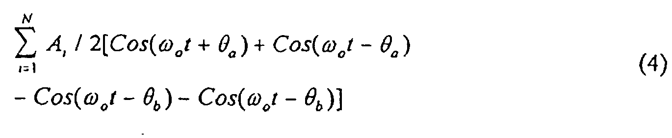
- Using the trigonometric identity:


- Equation (6) reduces to:


- Thus the present invention provides a true non contacting differential angular displacement (torque) measurement.
Claims (7)
- A non contacting torque sensor for a shaft (11) having a torsion bar (12) connecting two portions (11a, 11b) of said shaft comprising:a transmit annular disk (Tx) surrounding said shaft and fixed for non rotation;a pair of annular coupler disks (C1, C2) mounted for rotation with said shaft on opposite sides of said torsion bar, each coupler disk being made of insulating material and including a crescent-shaped symmetrical conductive pattern; anda pair of fixed receiver annular disks (RX1, RX2) surrounding said shaft with said coupler disks between them, said pair of receiver disks being adapted to receive signals from said transmit disk through said coupler disks indicative of the rotation of said shaftwherein each of the transmit and receive disks comprises six spiral loop antenna coils that are segmentally arranged in a circular pattern around the disk and circling the disk for a full 360° such that each spiral loop antenna coil is deformed to provide a 60° segment,
wherein the antenna coils on the transmit disk are inductively coupled to the antenna coils on the receive disk, such that in use the inductance is attenuated by the respective coupler disks having the crescent-shaped symmetrical conductive pattern such that six different amplitude signals are simultaneously generated at any one angular position of the sensor, the sensor further comprising means for angularly comparing said plurality of signals having different amplitudes from said pair of receiver disks to provide a torque signal indicative of the angular differential displacement of said shaft portions. - A torque sensor as in claim 1 where the transmit annular disk and the coupler disks are adapted to provide said signals to said receiver disks that have the same duty cycle with a phase shift between them proportional to the rotational differential displacement of said pair of coupler disks.
- A torque sensor as in claim 2 where said means for angularly comparing said plurality of signals having different amplitudes is adapted to provide an output signal with a changing duty cycle which is proportional to the differential displacement of one coupler disk from the other whereby said torque signal is indicated.
- A non contacting torque sensor as in claim 3 where said means for angularly comparing said plurality of signals having different amplitudes comprises an exclusive OR gate (51) for outputting the output signal with a changing duty cycle, whereby for clockwise or counter-clockwise rotation of the shaft said duty cycle respectively decreases or increases with respect to increase of torque.
- A non contacting torque sensor as in claim 1 where said shaft is an automobile steering column which is not physically connected to the wheels of the automobile and where an electric motor controls the steering which is actuated by said torque signal.
- A non contacting torque sensor as in claim 1 including means for shifting phase of at least one of said plurality of signals having different amplitudes by a fixed angle before said angularly comparing whereby crossover ambiguity is prevented.
- A non contacting torque sensor as in claim 6 where said fixed angle is 90° and a zero torque has a 50% duty cycle.
Applications Claiming Priority (2)
| Application Number | Priority Date | Filing Date | Title |
|---|---|---|---|
| US52708800A | 2000-03-16 | 2000-03-16 | |
| US527088 | 2000-03-16 |
Publications (2)
| Publication Number | Publication Date |
|---|---|
| EP1134567A1 EP1134567A1 (en) | 2001-09-19 |
| EP1134567B1 true EP1134567B1 (en) | 2006-11-08 |
Family
ID=24100040
Family Applications (1)
| Application Number | Title | Priority Date | Filing Date |
|---|---|---|---|
| EP01302388A Expired - Lifetime EP1134567B1 (en) | 2000-03-16 | 2001-03-15 | Non contacting torque sensor |
Country Status (3)
| Country | Link |
|---|---|
| EP (1) | EP1134567B1 (en) |
| JP (1) | JP2001304984A (en) |
| DE (1) | DE60124333T2 (en) |
Families Citing this family (4)
| Publication number | Priority date | Publication date | Assignee | Title |
|---|---|---|---|---|
| JP4107133B2 (en) * | 2003-04-02 | 2008-06-25 | 株式会社ジェイテクト | Torque sensor |
| JP4107134B2 (en) * | 2003-04-02 | 2008-06-25 | 株式会社ジェイテクト | Torque sensor |
| DE102008027719A1 (en) * | 2008-06-11 | 2009-12-17 | Hella Kgaa Hueck & Co. | Inductive torque sensor for motor vehicle, comprises four angle sensors, and associated unit for evaluation by regulation of differential angles, and two switching circuits are provided |
| JP6373962B2 (en) * | 2013-03-13 | 2018-08-15 | ティアックス エルエルシーTiax Llc | Torque sensor |
Family Cites Families (3)
| Publication number | Priority date | Publication date | Assignee | Title |
|---|---|---|---|---|
| JPS58214830A (en) * | 1982-06-08 | 1983-12-14 | Nippon Soken Inc | Torque detector |
| US4680976A (en) * | 1985-11-15 | 1987-07-21 | Vibro-Meter Sa | Torque or angle of torsion measuring device |
| DE3873257D1 (en) * | 1987-10-28 | 1992-09-03 | Rohs Ulrich | DEVICE FOR MEASURING THE TORQUE OF A WORK SHAFT. |
-
2001
- 2001-03-15 EP EP01302388A patent/EP1134567B1/en not_active Expired - Lifetime
- 2001-03-15 DE DE60124333T patent/DE60124333T2/en not_active Expired - Fee Related
- 2001-03-16 JP JP2001076326A patent/JP2001304984A/en active Pending
Also Published As
| Publication number | Publication date |
|---|---|
| DE60124333T2 (en) | 2007-04-26 |
| DE60124333D1 (en) | 2006-12-21 |
| EP1134567A1 (en) | 2001-09-19 |
| JP2001304984A (en) | 2001-10-31 |
Similar Documents
| Publication | Publication Date | Title |
|---|---|---|
| US6520031B2 (en) | Non contacting torque sensor | |
| US6304076B1 (en) | Angular position sensor with inductive attenuating coupler | |
| US11079291B2 (en) | Inductive position sensor | |
| CN115698662B (en) | Torque sensor | |
| US9914477B2 (en) | Inductive steering torque and angle sensor | |
| KR101944871B1 (en) | Steering position and torque sensor | |
| CN113825982B (en) | Rotor position sensor and motor vehicle steering system having a rotor position sensor | |
| US6661220B1 (en) | Antenna transponder configuration for angle measurement and data transmission | |
| US6448759B2 (en) | Non-contact linear position sensor for motion control applications with inductive attenuating coupler | |
| US20080116883A1 (en) | Inductive sensor for sensing of two coupling elements | |
| US20250093220A1 (en) | Improved inductive torsion bar torque sensor | |
| EP1795871A1 (en) | Multi-turn non-contact angular position sensor | |
| JP2003114103A (en) | Angle-of-rotation detector, torque detector and steering gear | |
| EP2881715B1 (en) | Self-calibrating position sensor | |
| US20090217774A1 (en) | Torque sensing apparatus | |
| EP1134567A1 (en) | Non contacting torque sensor | |
| US20110169483A1 (en) | Rotation angle detection device | |
| US20240077338A1 (en) | Inductive Sensor Arrangement for Detecting a Rotational Movement | |
| JP3940140B2 (en) | Multi-turn PWM generator, multi-turn angular position sensor, and method for generating a multi-turn pulse width modulated signal | |
| HK40088946B (en) | Torque sensing device | |
| HK40088946A (en) | Torque sensing device |
Legal Events
| Date | Code | Title | Description |
|---|---|---|---|
| PUAI | Public reference made under article 153(3) epc to a published international application that has entered the european phase |
Free format text: ORIGINAL CODE: 0009012 |
|
| AK | Designated contracting states |
Kind code of ref document: A1 Designated state(s): AT BE CH CY DE DK ES FI FR GB GR IE IT LI LU MC NL PT SE TR Kind code of ref document: A1 Designated state(s): DE FR GB |
|
| AX | Request for extension of the european patent |
Free format text: AL;LT;LV;MK;RO;SI |
|
| 17P | Request for examination filed |
Effective date: 20020121 |
|
| AKX | Designation fees paid |
Free format text: DE FR GB |
|
| 17Q | First examination report despatched |
Effective date: 20050321 |
|
| GRAP | Despatch of communication of intention to grant a patent |
Free format text: ORIGINAL CODE: EPIDOSNIGR1 |
|
| GRAS | Grant fee paid |
Free format text: ORIGINAL CODE: EPIDOSNIGR3 |
|
| GRAA | (expected) grant |
Free format text: ORIGINAL CODE: 0009210 |
|
| AK | Designated contracting states |
Kind code of ref document: B1 Designated state(s): DE FR GB |
|
| REG | Reference to a national code |
Ref country code: GB Ref legal event code: FG4D |
|
| REF | Corresponds to: |
Ref document number: 60124333 Country of ref document: DE Date of ref document: 20061221 Kind code of ref document: P |
|
| PGFP | Annual fee paid to national office [announced via postgrant information from national office to epo] |
Ref country code: GB Payment date: 20070327 Year of fee payment: 7 |
|
| PGFP | Annual fee paid to national office [announced via postgrant information from national office to epo] |
Ref country code: DE Payment date: 20070430 Year of fee payment: 7 |
|
| ET | Fr: translation filed | ||
| PLBE | No opposition filed within time limit |
Free format text: ORIGINAL CODE: 0009261 |
|
| STAA | Information on the status of an ep patent application or granted ep patent |
Free format text: STATUS: NO OPPOSITION FILED WITHIN TIME LIMIT |
|
| 26N | No opposition filed |
Effective date: 20070809 |
|
| PGFP | Annual fee paid to national office [announced via postgrant information from national office to epo] |
Ref country code: FR Payment date: 20070319 Year of fee payment: 7 |
|
| GBPC | Gb: european patent ceased through non-payment of renewal fee |
Effective date: 20080315 |
|
| REG | Reference to a national code |
Ref country code: FR Ref legal event code: ST Effective date: 20081125 |
|
| PG25 | Lapsed in a contracting state [announced via postgrant information from national office to epo] |
Ref country code: DE Free format text: LAPSE BECAUSE OF NON-PAYMENT OF DUE FEES Effective date: 20081001 |
|
| PG25 | Lapsed in a contracting state [announced via postgrant information from national office to epo] |
Ref country code: FR Free format text: LAPSE BECAUSE OF NON-PAYMENT OF DUE FEES Effective date: 20080331 |
|
| PG25 | Lapsed in a contracting state [announced via postgrant information from national office to epo] |
Ref country code: GB Free format text: LAPSE BECAUSE OF NON-PAYMENT OF DUE FEES Effective date: 20080315 |