EP1133833B1 - Method and apparatus for time tracking a signal - Google Patents
Method and apparatus for time tracking a signal Download PDFInfo
- Publication number
- EP1133833B1 EP1133833B1 EP00967393A EP00967393A EP1133833B1 EP 1133833 B1 EP1133833 B1 EP 1133833B1 EP 00967393 A EP00967393 A EP 00967393A EP 00967393 A EP00967393 A EP 00967393A EP 1133833 B1 EP1133833 B1 EP 1133833B1
- Authority
- EP
- European Patent Office
- Prior art keywords
- signal
- late
- energy value
- early
- block
- Prior art date
- Legal status (The legal status is an assumption and is not a legal conclusion. Google has not performed a legal analysis and makes no representation as to the accuracy of the status listed.)
- Expired - Lifetime
Links
- 238000000034 method Methods 0.000 title claims description 32
- 238000004891 communication Methods 0.000 claims description 57
- 238000001914 filtration Methods 0.000 claims description 17
- 230000004044 response Effects 0.000 claims description 10
- 230000002123 temporal effect Effects 0.000 claims description 9
- 238000004590 computer program Methods 0.000 claims 2
- 230000015654 memory Effects 0.000 description 51
- 238000012937 correction Methods 0.000 description 9
- 230000006870 function Effects 0.000 description 9
- 238000010586 diagram Methods 0.000 description 6
- 230000008569 process Effects 0.000 description 6
- 238000012545 processing Methods 0.000 description 6
- 238000012986 modification Methods 0.000 description 5
- 230000004048 modification Effects 0.000 description 5
- 238000010606 normalization Methods 0.000 description 4
- 229910000497 Amalgam Inorganic materials 0.000 description 3
- 230000005055 memory storage Effects 0.000 description 3
- 230000005540 biological transmission Effects 0.000 description 2
- 238000007796 conventional method Methods 0.000 description 2
- 230000008878 coupling Effects 0.000 description 2
- 238000010168 coupling process Methods 0.000 description 2
- 238000005859 coupling reaction Methods 0.000 description 2
- 238000013461 design Methods 0.000 description 2
- 230000000694 effects Effects 0.000 description 2
- 238000011156 evaluation Methods 0.000 description 2
- 230000010355 oscillation Effects 0.000 description 2
- 230000001902 propagating effect Effects 0.000 description 2
- 238000001228 spectrum Methods 0.000 description 2
- 230000007480 spreading Effects 0.000 description 2
- 238000003892 spreading Methods 0.000 description 2
- 230000009471 action Effects 0.000 description 1
- 239000000654 additive Substances 0.000 description 1
- 230000000996 additive effect Effects 0.000 description 1
- 238000004458 analytical method Methods 0.000 description 1
- 230000008901 benefit Effects 0.000 description 1
- 238000004364 calculation method Methods 0.000 description 1
- 230000001413 cellular effect Effects 0.000 description 1
- 230000008859 change Effects 0.000 description 1
- 230000002596 correlated effect Effects 0.000 description 1
- 230000000875 corresponding effect Effects 0.000 description 1
- 238000013500 data storage Methods 0.000 description 1
- 230000001419 dependent effect Effects 0.000 description 1
- 230000001066 destructive effect Effects 0.000 description 1
- 238000005516 engineering process Methods 0.000 description 1
- 238000005562 fading Methods 0.000 description 1
- 238000004519 manufacturing process Methods 0.000 description 1
- 238000012067 mathematical method Methods 0.000 description 1
- 230000007246 mechanism Effects 0.000 description 1
- 230000035484 reaction time Effects 0.000 description 1
- 230000000979 retarding effect Effects 0.000 description 1
- 230000002441 reversible effect Effects 0.000 description 1
- 238000005070 sampling Methods 0.000 description 1
- 238000003860 storage Methods 0.000 description 1
- 239000000126 substance Substances 0.000 description 1
- 230000001360 synchronised effect Effects 0.000 description 1
- 238000013519 translation Methods 0.000 description 1
Images






Classifications
-
- H—ELECTRICITY
- H04—ELECTRIC COMMUNICATION TECHNIQUE
- H04B—TRANSMISSION
- H04B1/00—Details of transmission systems, not covered by a single one of groups H04B3/00 - H04B13/00; Details of transmission systems not characterised by the medium used for transmission
- H04B1/69—Spread spectrum techniques
- H04B1/707—Spread spectrum techniques using direct sequence modulation
- H04B1/7073—Synchronisation aspects
- H04B1/7085—Synchronisation aspects using a code tracking loop, e.g. a delay-locked loop
-
- H—ELECTRICITY
- H04—ELECTRIC COMMUNICATION TECHNIQUE
- H04B—TRANSMISSION
- H04B1/00—Details of transmission systems, not covered by a single one of groups H04B3/00 - H04B13/00; Details of transmission systems not characterised by the medium used for transmission
Definitions
- the present claimed invention relates to the field of digital communication. Specifically, the present claimed invention relates to an apparatus and a method for providing time tracking of a signal using hardware and software.
- Wireless telephony e.g. cellular phone use
- Variable rate communication systems such as Code Division Multiple Access (CDMA) spread spectrum systems
- CDMA Code Division Multiple Access
- a conventional base station 104 and a mobile unit 102 e.g. a cell phone
- a CDMA system uses a common bandwidth to transmit the pilot signal and a data signal 106 between a base station 104 and a mobile unit 102, for multiple users.
- the bandwidth is occupied by an amalgam of many signals.
- the individual signal is modulated at the transmitter and demodulated at the receiver.
- the modulation code used for CDMA is a pseudonoise (PN), e.g. an apparently random sequence of 1's 120 and 0's 118 having a given length, e.g. 100a.
- PN pseudonoise
- a "long" PN sequence is used to scramble user data, while a “short” PN sequence is used to spread quadrature components for the forward and reverse link wave forms.
- the short PN sequence is used for a pilot signal.
- a base station broadcasts a pilot signal to which a mobile receiver may receive and synchronize, for time tracking purposes.
- a first signal 114a of a conventional PN sequence e.g. 110a
- a first device such as a mobile unit 102 of prior art Figure 1A
- the same conventional PN sequence e.g. 112a
- a second device such as a base station 104 of prior art figure 1A.
- the mobile unit and base station can communicate to each other when they properly align the starting points of the known PN sequence.
- Proper alignment is utterly critical, in applications such as CDMA, because it is necessary for accurately applying the PN sequence to demodulate a signal out of the amalgam of signals that occupy the bandwidth.
- a signal may be correctly aligned at the beginning of the signal, e.g. 116, it may not be properly aligned throughout the entire signal, e.g. offset error 118, as shown in prior art Figure 1A.
- the misalignment can arise from a difference in the frequency V cxo of the PN sequence generated at each unit. This is referred to as a frequency offset between a base station and a mobile unit.
- Determining the alignment of the signals can be accomplished by performing digital signal processing (DSP), such as a correlation operation, on the signals.
- DSP digital signal processing
- imperfections in transmitting, receiving, modulating, and demodulating a signal inherently integrate noise into the signal.
- the noise hampers, and sometimes prevents, the DSP operation to demodulate a signal and receive the data contained therein.
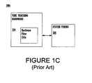
- a conventional time tracking block diagram is shown.
- Conventional time tracking uses hardware 254 to perform the time tracking operations and provide input to system timing 256.
- the time tracking hardware removes noise from the signal by passing the signal through a hardware filter 254a.
- the conventional filter 254a has a fixed configuration. That is, the conventional fitter has a single configuration that cannot be changed, unless the hardware is redesigned and replaced.
- different operating circumstances and resources for a communication device or a communication system may allow or demand higher or lower performance filters. To optimize performance and resources, a need arises to provide a flexible filter for removing noise from data used for time tracking.
- a signal Once correlated and normalized, it can be compared to a threshold.
- Conventional methods divide correlation data by a normalizing value. However, a division operation is more difficult to implement in an electronic component. Consequently, a need arises to simplify the normalization operation of a threshold value used for time tracking.
- a filter used for correlation data is not reset after a timing correction is made. Consequently, the filter retains and evaluates some obsolete data for a subsequent timing correction.
- This practice can provide incorrect timing corrections and possibly lead to timing oscillation. Overall, the conventional practice degrades system performance. Hence, a need arises for a method to avoid filtering obsolete data once a timing correction has been made.
- an apparatus and a method is needed to improve the capacity, fidelity, and performance of digital communication. More specifically, a need arises for time tracking a signal generated within a mobile device to a signal received from a base station to ensure proper alignment of the signals. To improve the time tracking, a need arises to remove the noise from the correlation data used for time tracking. To optimize performance and resources, a need arises to provide a flexible filter for removing noise from pilot channel used for time tracking. Also, a need arises for a method to avoid filtering obsolete data once a timing correction has been made. Additionally, a need arises to simplify the normalization operation of a threshold value used for time tracking.
- US-A-5 867 525 describes a spread spectrum synchronous communications system in which synchronization is accomplished by using three despreaders. Each despreader receives a spreading code with a different amount of delay imposed on that spreading code. The outputs of the three despreaders are digitally combined, or compared, to produce an offset estimate, which is used to correct synchronization.
- the present invention provides a method and apparatus for improving the capacity, fidelity, and performance of digital communication. More specifically, the present invention provides improved time tracking between a signal from a base station and a signal generated within a mobile device. The present invention improves time tracking by remove noise from the correlation data used for time tracking. To optimize performance and resources, the present invention provides a flexible filter for removing noise from correlation data used in time tracking. Additionally, the present invention provides a method to avoid filtering obsolete data once a timing correction has been made, thereby improving system performance. Additionally, the present invention provides a more efficient method of normalizing a threshold value used for time tracking. By implementing the filtering function using software or firmware, the present invention provides a very flexible and adjustable filter. For example, the filter coefficients can be quickly and inexpensively modified without hardware modifications. Thus the present invention overcomes the drawbacks of the prior art filter which was implemented in hardware.
- the present invention recites a method comprising several steps.
- a communication device such as a cell phone
- a communication device such as a cell phone
- Both signals are designed to have the same finite and repeating, but not necessarily aligned, pseudonoise (PN) sequence that can be used to synchronize the timing between the two devices.
- PN pseudonoise
- correlation data between a first signal, at a plurality of timing conditions, and a second signal is generated by hardware in the communication device.
- the plurality of timing conditions allows an on-time condition, an early condition, and a late condition of the first signal to be evaluated for alignment with the second signal. By evaluating several timing conditions, the direction for optimal correlation between the signals can be determined.
- the correlation data is filtered by software or firmware at the plurality of timing conditions to remove noise and thereby provide more accurate correlation data for subsequent evaluation.
- the correlation data is normalized and compared to a threshold value to obtain a result that represents the accuracy of a system timing for the first signal.
- One embodiment normalizes the threshold value using a more efficient multiplication operation in lieu of the conventional division operation. Specifically, the threshold value is multiplied by the on-time energy value resulting from correlation between the first signal and the second signal. This normalized threshold value is compared to the difference between the early energy and the late energy calculation resulting from correlation between the first signal to the second signal. Finally, the system timing for the first signal is corrected based upon the result of the comparing step.
- the present invention recites a communication device including hardware, a processor and a computer readable memory.
- the memory contains program instructions that, when executed via the processor, implement the aforementioned method for determining translation error in a stepper.
- the data is represented as physical (electronic) quantities within the communication devices components, or the computer system's registers and memories, and is transformed into other data similarly represented as physical quantities within the communication device components, or computer system memories or registers, or other such information storage, transmission or display devices.
- Communication device 200a includes a time tracking block 208 coupled to a system timing block 210.
- Time tracking block 208 includes a correlation hardware block 209a coupled to a filtering software block 209b.
- the present invention provides a hybrid device having optimal and flexible time tracking.
- Communication device 200b includes an antenna 202, a transceiver block 204, a PN generator block 206, a time tracking block 208, external memory 231, a Central Processing Unit (CPU) 233, and a processor block 220.
- Antenna 202 is coupled to transceiver block 204, which is in turn coupled to time tracking block 208.
- PN generator block 206 is also coupled to time tracking block 208.
- Processor 220 is coupled to time tracking block 208.
- CPU 233 is coupled to processor and to external memory.
- External memory 231 is coupled to time tracking block 208.
- External memory 231 can be Electrically Erasable Programmable Read Only Memory (EEPROM), flash memory, or any other type of memory configuration.
- EEPROM Electrically Erasable Programmable Read Only Memory
- time tracking block 208, CPU 233, PN generator 206, and processor 220 are on-chip, while external memory 231 is off-chip.
- the present invention is well-suited to using any combination of components either on-chip or off-chip.
- Time tracking block 208 of Figure 2B includes a correlation hardware block 209a, a filtering software block 209b, and a patch block 209c coupled to each other.
- Time tracking block 208 also includes an accumulate block 232 and a compare block 230.
- Compare block 230 is coupled to filtering software block 209b and to accumulate block 232.
- Accumulate block is coupled to filtering software block 209b and correlation hardware block 209a.
- Compare block 230 and accumulate block 232 can be implemented either as hardware or software in communication device 200b.
- Patch block 209a can be RAM or some other form of memory device. In an alternative embodiment, if filtering software block 209b is RAM, then patch block 209c is not needed.
- Correlation hardware block 209a of Figure 2B includes a block for correlating an on-time condition 211, an early condition 212, and a late condition 213. Output from early condition block 212 and output from late condition block 213 are subtracted from each other by a block 214 that performs a logical difference operation. One embodiment implements the logical difference operation by negating one signal then adding it to the other signal.
- Filtering software block 209b of Figure 2B includes an Infinite Impulse Response (IIR) filter Y block 224, an IIR filter X block 226, a memory block 222, and a multiplication operation block 225, all coupled together.
- memory 222 can be read only memory (ROM), including programmable and non-programmable ROM, e.g. firmware.
- Memory 222 can also be any other type of memory storage, capable of containing program instructions, such as a hard drive, CD ROM, or flash memory.
- Memory block 222 includes data registers for filter coefficient 212a, which intrinsically indicates a filter order, threshold 212c, update rate 212d, and temporal offset 212e, for use in time tracking block 208.
- the present invention can include more or less data registers than those shown in the present embodiment. While the present embodiment utilizes an IIR filter, the present invention is well-suited to any kind of digital filter, e.g. a Finite Impulse Response (FIR).
- FIR Finite Impulse Response
- filter coefficient block 212a is coupled to IIR filter Y block 224 and IIR filter X block 226. While the present embodiment utilizes only a first-order filter, having a single coefficient, e.g. stored in coefficient block 212a, the present invention is well-suited to having a higher order filter. The higher order filter embodiment will use multiple coefficient blocks in memory to store the coefficient values.
- the output from IIR filer Y block and threshold data block 212c are both coupled to multiplication operation block 225.
- Output from IIR filter X block 226 and multiplication operation block 225 are both coupled to compare block 230.
- Output from compare block and update rate block 212d of memory block 222 are both coupled to accumulate block 232.
- Output from accumulate block 232 is coupled to IIR filter X 226 and to correlation hardware block 209a.
- Temporal offset block 212e of memory block 222 is coupled to early block 212 and late block 213 of correlation hardware block 209a.
- PN generator block 206 can be incorporated into time tracking block 208.
- Graph 200c has an abscissa axis representing the independent variable of offset 242 between two signals.
- Graph 200c has an ordinate axis representing the dependent variable of energy 240 calculated between the two signals over a range of offset values 242.
- Energy value 240 represents the correlation obtained by multiplying two signals together at corresponding times and summing the results over time.
- data point 252 represents, in one embodiment, correlation between two identical propagating signals totally out of phase with each other.
- the offset 250 in this case is equivalent to one chip, of data for the given transmission rate in CDMA, in one embodiment.
- the resulting destructive interference between the two signals will essentially drive the correlation, e.g. the sum of the product of the two signals, to a mean value of zero.
- correlation is illustrated as a convenient mathematical method of determining how well two signals match each other.
- a CDMA system needs the modulation sequence, rate, and alignment signal at one unit to be accurately timed to the demodulation sequence, rate, and alignment at another unit.
- Points 246a, 246b, and 246c represent a series of correlation's at a consistent differential offset from each other. By examining the correlation values at different offsets, e.g. at points 246a, 246b, and 246c, it can be determined in which direction an optimal correlation value can be obtained, and thus the ideal synchronization timing.
- perfect system timing is represented, in Figure 2C, by an on-time energy value located at point 244b, a late energy value located at point 244a, and an early energy value located at point 244c.
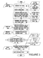
- FIG. 3 a flowchart of the steps used to implement time tracking in a communication device using hardware and software is shown, in accordance with one embodiment of the present invention.
- a very accurate and flexible time tracking operation can be implemented. Consequently, the present invention provides improved capacity, fidelity, and performance of digital communications.
- the present embodiment applies flowchart 300 to a CDMA digital communication system, the present invention can be applied to any communication system needing time tracking. Also, the present invention is applicable to both mobile units and base stations used for telecommunications operations. While the present embodiment is applied to wireless communication system, the present invention is equally applicable to coupled devices.
- Flowchart 300 begins with step 302.
- a first signal is generated at a communication device.
- Step 302 is implemented, in one embodiment, by the blocks illustrated in Figure 2B.
- first signal is generated by communication device 200a using methods known in the art, such as a Linear Feedback Shift Register (LFSR).
- LFSR Linear Feedback Shift Register
- the PN generator block 206 can generate the first signal by many different means, such as retrieving stored memory or by evaluating an mathematical formula.
- Step 302 has an input of temporal offset 302a.
- the temporal offset 302a determines the amount of timing offset between the early and the late version of the first signal to the on-time version of the first signal. Consequently, first step 302 provides outputs including an on-time signal 302a, an early signal 302b, and a late signal 302c.
- flowchart 300 proceeds to step 304.
- the temporal offset value is stored in memory 222 of communication device 200b.
- a second signal is received at a communication device.
- Step 304 is implemented for both an in-phase portion and a quadrature-phase portion of the second signal.
- Step 304 is implemented, in one embodiment, by the blocks illustrated in Figure 2B.
- digital communication system 200a receives a signal on antenna 202 in this embodiment.
- a second signal is transmitted between a base station and a mobile unit.
- alternative devices and configurations can be used with the present invention.
- the received signal is then transmitted to the time tracking block 208 for subsequent processing.
- modulation is performed using known PN sequences. To synchronize a base station and a mobile unit, the known PN sequences are aligned.
- first signal and second signal are ideally the identical and timely-synchronized PN sequence.
- the present invention is also well-suited to using the present embodiment for time tracking non-identical signals. For example, noise may corrupt one of the signals such that it is similar, but not identical, to the second signal.
- flowchart 300 proceeds to step 306.
- step 306 of the present embodiment correlation data between the first signal and the second signal is generated.
- Step 306 receives the output from step 304, e.g. second signal, and from step 302, e.g. on-time signal 302a, early signal 302b and late signal 302c.
- step 306 generates correlation data between first signal, at an on-time condition, with a second signal to provide an output on-time energy value 306a.
- step 306 generates correlation data between first signal, at an early timing condition, with a second signal to provide an output early energy value 306b.
- step 306 generates correlation data between first signal, at a late timing condition, with a second signal to provide an output late energy value 306c. While step 306 utilizes a specific quantity and amount of timing offsets, the present invention is well-suited to any quantity of timing conditions at any amount of timing offsets.
- Step 306 is implemented, in one embodiment, by the blocks illustrated in Figure 2B.
- correlation data is generated in the present embodiment by correlation hardware block 209a. That is, on-time block 211, early block 212, and late block 213 each generate their respective correlation data for the appropriate time condition.
- blocks 211, 212, and 213 utilize quadrature despreading hardware, accumulator hardware, summer hardware, and logical-multiplication hardware to accomplish the correlation data.
- the present invention is well-suited to many different hardware combinations that can accomplish the correlation operation.
- flowchart 300 proceeds to step 308.
- a late energy value minus the early energy value is determined, thereby generating a late-early energy value.
- Step 308 is implemented, in one embodiment, by the blocks illustrated in Figure 2B.
- a logical subtraction device 214 can be used to find the mathematical difference between the late energy value determined by late block 213 and the early energy value determined by early block 212.
- the subtraction operation will be implemented using an inverter and a summing device.
- the present invention is well suited to many different devices to accomplish the logical subtraction operation.
- step 310 of the present embodiment correlation data is filtered. Specifically, step 310 filters the late-early energy value, and the on-time energy value.
- Step 310 is implemented, in one embodiment, by the software illustrated in Figure 2B. Specifically, filtering software 209b is utilized to filter the correlation data provided by correlation hardware block 209a.
- the software is stored as program instructions, or code, in a computer readable memory unit, and executed, via a processor 220.
- firmware can be used to implement a flexible filter for step 310.
- FIG. 2B shows functional blocks for software filter.
- filtering software block 209b provides more discrete blocks to implement the filtering function.
- IIR filter Y block 224 filters data from the on-time signal provided by on-time block 211 in the correlation hardware block 209a.
- IIR filter X block 226 filters data from the difference operation block 214 performed on data from the early block 212 and late block 213.
- Step 310 also includes, but is not limited to, a filter bandwidth input 310a.
- Filter bandwidth can also be referred to as a filter coefficient, or as a forgetting factor.
- the quantity of filter coefficients entered for the filter intrinsically indicates the order of the filter.
- Filter order indicates the order of the digital filter, which indicates how many terms the filter equation utilizes.
- Filter bandwidth input 310a is implemented, in one embodiment, as shown in Figure 2B, as data 212a, for filter coefficient, stored in memory 222 of communication device 200b.
- the present invention improves time tracking by optimally removing noise from the signal being tracked. That is, the filter design is not rigidly fixed in a hardware design like the prior art. Instead, it can easily be changed with a new data input for a filter variable such as filter bandwidth, which intrinsically includes the filter order. Any type of data storage can be utilized for data in memory 222. More specifically, by using the present embodiment, the present invention optimizes performance and resources of the communication network by providing a flexible filter for removing noise from data used in time tracking. Following step 310, flowchart 300 proceeds to step 312
- a threshold value is normalized.
- SNR Signal to Noise Ratio
- normalization of the threshold value emphasizes the variable of interest, the timing error between the first signal and the second signal.
- correlation data provided in Figure 2C indicates the correlation results of a strong signal 248, having higher energy values, and correlation results for a weak signal 249, having lower energy values.
- the stronger signal has a larger correlation value because the signal amplitude is high.
- the weaker signal has a smaller correlation value because the signal amplitude is low.
- normalizing the signal e.g.
- the present embodiment multiplies the threshold value by one energy value to provide the same effect. That is, the normalized threshold value is defined as the threshold value multiplied by the on-time energy value.
- the temporal distance 256 represents the difference between late energy and early energy, e.g. E L-E .
- the Signal to Noise (SNR) ratio affects the results of E L-E . That is, the difference in energy value between point 246a and 246c is greater for a strong signal, e.g. represented by curve 248, than for a weak signal, e.g. represented by curve 249.
- a threshold value e.g. T
- the threshold value, T is essentially normalized by multiplying it by the on-time energy value to obtain a normalized threshold value, T N .
- T N a normalized threshold value
- Step 312 in one embodiment, includes, but is not limited to, a threshold value 310a input, and an on-time energy value, obtained from step 306.
- Step 312 may be implemented, in one embodiment, by the software and hardware illustrated in Figure 2B. Specifically, threshold value input 310a for flowchart 300 is implemented in the embodiment of Figure 2B, as data 212c stored in memory 222 of filtering software block 209b for communication device 200a.
- Step 312 is implemented in one embodiment, as shown in Figure 2B, where a logical multiplication block 225 multiplies data from IIR filter Y 224 and from threshold data 212c stored in memory 222.
- a logical multiplication block 225 multiplies data from IIR filter Y 224 and from threshold data 212c stored in memory 222.
- an inquiry determines whether the late-early energy value is greater than, less than, or equal to the normalized threshold value. More specifically, if the late-early energy value is greater than the absolute value of the normalized threshold value, e.g. E L-E' >
- the late-early energy value is less than, or equal to, the absolute value of the normalized threshold value and greater than, or equal to, the negated absolute value of the normalized threshold value, e.g. -
- compare block 230 evaluates the normalized threshold data provided by logical multiplication block 225, and it evaluates the filtered late-early energy value data provided by IIR filter X block 226.
- Compare block 230 can be implemented as software or as hardware: Following step 314, flowchart 300 proceeds to step 316.
- step 316 of the present embodiment responses to the inquiry of step 314 are accumulated to adjust system timing.
- Step 316 is implemented, in one embodiment, by the blocks illustrated in Figure 2B. Specifically, accumulate block 232 accumulates responses from compare block 230. In one embodiment, the system timing is adjusted in a separate step in response to the accumulated responses to step 314 and the update rate 316a enabling input. In one embodiment, input 316a is implemented by the embodiment of Figure 2B as memory block 212d. Accumulate block 232 receives an update rate 212d from memory 222 of communication device 200b. The update rate dictates how often the frequency of the first signal is corrected in response to the results of comparison step 314.
- the adjustment to the first signal of step 316 is responsive to the results of the comparison step 314. Specifically, if the accumulated data in step 316 indicates a "+1" from the comparison, then system timing for the first signal is retarded. If the accumulated data in step 316 indicates a "-1" from the comparison, then system timing for the first signal is advanced. And if the accumulated data in step 316 indicates a "0" from the comparison, then system timing for the first signal is unchanged.
- the present invention is well-suited to alternative control mechanisms than those used in the present embodiment, such as different codes other than +1,-1, and 0.
- Step 316 is implemented, in one embodiment, by the blocks shown in Figure 2B. Specifically, accumulate block 232 is coupled to, and provides the system timing changes to, correlation block 209a. Time tracking block is coupled to PN generator block 206, and thus can pass system timing changes to it. Accumulate block 232 can be implemented either as hardware or as software. Following step 316, flowchart 300 proceeds to step 320.
- the late-early filter e.g. used to filter the numerical difference between late energy value minus early energy value
- Step 320 is implemented, in one embodiment, by the blocks shown in Figure 2B.
- IIR filter X block 226 is reset.
- IIR filter X block 226 filters the values resulting from subtracting late energy from early energy. This step is shown figuratively by coupling accumulate block 232 to IIR filter X block 226 by a dashed line.
- resetting the filter is implemented by zeroing out previous output values considered by an IIR filter. Alternatively, previous values of input considered by an FIR filter are zeroed out.
- flowchart 300 ends.
- processor 220 can either be permanent, such as read only memory (ROM), or temporary memory such as random access memory (RAM).
- Memory 222- can also be any other type of memory storage, capable of containing program instructions, such as a hard drive, a CD ROM, or flash memory.
- processor 220 can either be an existing system processor, or it can be a dedicated digital signal processing (DSP) processor.
- DSP digital signal processing
- the instructions may be implemented using a microcontroller or some other state machine.
- the present invention provides dynamic time tracking and/or dynamic filtering.
- inputs used in flowchart 300 can be stored in memory.
- their values can be changed, in one embodiment, without changing hardware components in the communication device.
- Data can be loaded into memory, e.g. 222; of communication device 200b of Figure 2B, e.g. mobile unit or base station unit, at the time of manufacture or during service.
- new performance values can be transmitted with system information to the communication device.
- This embodiment can be implemented as shown in Figure 2B where antenna 202 can receive a system data signal from another device, such as a base station.
- the system data signal is demodulated by the transceiver 204 and communicated to the time tracking block 208.
- Appropriate data values from the system data signal can be stored in memory block 222 of filtering software 209b.
- time tracking and/or filter performance of a unit can be varied quickly, easily, and transparently to the user.
- This embodiment could provide tailored filtering for communication devices based on variables such as geographical location that would account for electromagnetic interference levels, signal traffic, physical obstructions, and other considerations.
- This embodiment can be implementing, as shown in Figure 2B. If filtering software 209b is stored in Random Access Memory (RAM), then the filter inputs and instructions can simply be rewritten over previous RAM data. The new inputs and instructions can come from external memory, e.g. external memory 231, or from an external input device.
- RAM Random Access Memory
- filtering software 209b is stored in Read Only Memory (ROM)
- inputs and instructions for the filter can be downloaded from an external memory device, e.g. external memory 231, such as flash memory or Electrically Erasable Programmable Read Only Memory (EEPROM), to on-chip memory, e.g. patch memory 209c.
- external memory 231 such as flash memory or Electrically Erasable Programmable Read Only Memory (EEPROM)
- EEPROM Electrically Erasable Programmable Read Only Memory
- patch memory 209c Instructions and data on patch memory 209c are subsequently implemented in time tracking block 208 in lieu of those provided by filtering software 209b.
- the communication device may be modified by mechanically linking and downloading new data to the communication device.
- flowchart 300 of the present embodiment shows a specific sequence and quantity of steps
- the present invention is suitable to alternative embodiments. For example, not all the steps provided for flowchart 300 are required for the present invention. And additional steps may be added to those presented. Likewise, the sequence of the steps can be modified depending upon the application.
- flowchart 300 is shown as a single serial process, it can also be implemented as a continuous or parallel process. For example, instead of proceeding to end step, flowchart 300 could return to the start step or to step 310, in different embodiments, to continuously perform correlation and/or filtering operations.
- the digital filter bandwidth is proportional to the update rate in one embodiment. With an update rate of once per 20 millisecond, e.g. 50 Hz, the digital filter -1 dB bandwidth should be around 50 Hz.
- the present invention is suitable to using a wide range of update rates, or to using a real time configuration.
- Optimal bandwidth can be determined by using Signal Processing Workstation (SPW) to simulate both Additive White Gaussian Noise (AWGN) and fading environment.
- SPW Signal Processing Workstation
- AWGN Additive White Gaussian Noise
- the purpose of using an update rate is to control when the system timing can be changed. By providing a time delay between modifications to system timing, the present embodiment allows the system to stabilize before making a subsequent change. In other words, the system timing and the present time tracking and updating blocks act as a control system.
- the present embodiment only allows changes when the update rate allows it to.
- the present invention is well-suited to using a real time updating system as well.
- system response time, lead time, and lag time, and reaction time in general, can be considered in using an update rate configuration or a real-time update configuration.
- the present invention effectively provides a method and apparatus for improving the capacity, fidelity, and performance of digital communication. More specifically, the present invention provides improved time tracking between a signal from a base station and a signal generated within a mobile device. The present invention also improves time tracking by remove the noise from the correlation data used for time tracking. To optimize performance and resources, the present invention provides a flexible filter for removing noise from correlation data used in time tracking. Also, the present invention provides a method to avoid filtering obsolete data once a timing correction has been made, thereby improving system performance. Additionally, the present invention provides a more efficient method of normalizing a threshold value used for time tracking.
Landscapes
- Engineering & Computer Science (AREA)
- Computer Networks & Wireless Communication (AREA)
- Signal Processing (AREA)
- Mobile Radio Communication Systems (AREA)
Description
- The present claimed invention relates to the field of digital communication. Specifically, the present claimed invention relates to an apparatus and a method for providing time tracking of a signal using hardware and software.
- Wireless telephony, e.g. cellular phone use, is a widely-used mode of communication today. Variable rate communication systems, such as Code Division Multiple Access (CDMA) spread spectrum systems, are among the most commonly deployed technology. Because of increasing demand and limited resources, a need arises to improve their capacity, fidelity, and performance.
- Referring to prior art Figure 1A, a
conventional base station 104 and amobile unit 102, e.g. a cell phone, are shown. A CDMA system uses a common bandwidth to transmit the pilot signal and adata signal 106 between abase station 104 and amobile unit 102, for multiple users. Hence, the bandwidth is occupied by an amalgam of many signals. In order to extract an individual signal from the amalgam of signals, the individual signal is modulated at the transmitter and demodulated at the receiver. - Referring now to prior art Figure 1 B, two signals having an
exemplary PN sequence 100b are shown. The modulation code used for CDMA is a pseudonoise (PN), e.g. an apparently random sequence of 1's 's 118 having a given length, e.g. 100a. A "long" PN sequence is used to scramble user data, while a "short" PN sequence is used to spread quadrature components for the forward and reverse link wave forms. - The short PN sequence is used for a pilot signal. A base station broadcasts a pilot signal to which a mobile receiver may receive and synchronize, for time tracking purposes. Thus, as shown in prior art Figure 1B, a first signal 114a of a conventional PN sequence, e.g. 110a, is repeatedly generated, e.g. 110b, by a first device such as a
mobile unit 102 of prior art Figure 1A. Similarly, the same conventional PN sequence, e.g. 112a, is repeatedly generated, e.g. 112b, by a second device such as abase station 104 of prior art figure 1A. - The mobile unit and base station can communicate to each other when they properly align the starting points of the known PN sequence. Proper alignment is utterly critical, in applications such as CDMA, because it is necessary for accurately applying the PN sequence to demodulate a signal out of the amalgam of signals that occupy the bandwidth. While a signal may be correctly aligned at the beginning of the signal, e.g. 116, it may not be properly aligned throughout the entire signal,
e.g. offset error 118, as shown in prior art Figure 1A. The misalignment can arise from a difference in the frequency Vcxo of the PN sequence generated at each unit. This is referred to as a frequency offset between a base station and a mobile unit. Hence a need arises for time tracking a signal generated by one device with a signal received from another device to ensure proper alignment of the signals for modulation and demodulation. - Determining the alignment of the signals can be accomplished by performing digital signal processing (DSP), such as a correlation operation, on the signals. However, imperfections in transmitting, receiving, modulating, and demodulating a signal, inherently integrate noise into the signal. The noise hampers, and sometimes prevents, the DSP operation to demodulate a signal and receive the data contained therein. To improve the time tracking operation, a need arises to remove the noise from the correlation data used for time tracking.
- Referring now to prior art Figure 1C, a conventional time tracking block diagram is shown. Conventional time tracking uses
hardware 254 to perform the time tracking operations and provide input tosystem timing 256. Conventionally, the time tracking hardware removes noise from the signal by passing the signal through ahardware filter 254a. However, by using hardware, theconventional filter 254a has a fixed configuration. That is, the conventional fitter has a single configuration that cannot be changed, unless the hardware is redesigned and replaced. But different operating circumstances and resources for a communication device or a communication system may allow or demand higher or lower performance filters. To optimize performance and resources, a need arises to provide a flexible filter for removing noise from data used for time tracking. - Once a signal is correlated and normalized, it can be compared to a threshold. Conventional methods divide correlation data by a normalizing value. However, a division operation is more difficult to implement in an electronic component. Consequently, a need arises to simplify the normalization operation of a threshold value used for time tracking.
- Conventionally, a filter used for correlation data is not reset after a timing correction is made. Consequently, the filter retains and evaluates some obsolete data for a subsequent timing correction. This practice can provide incorrect timing corrections and possibly lead to timing oscillation. Overall, the conventional practice degrades system performance. Hence, a need arises for a method to avoid filtering obsolete data once a timing correction has been made.
- In summary, an apparatus and a method is needed to improve the capacity, fidelity, and performance of digital communication. More specifically, a need arises for time tracking a signal generated within a mobile device to a signal received from a base station to ensure proper alignment of the signals. To improve the time tracking, a need arises to remove the noise from the correlation data used for time tracking. To optimize performance and resources, a need arises to provide a flexible filter for removing noise from pilot channel used for time tracking. Also, a need arises for a method to avoid filtering obsolete data once a timing correction has been made. Additionally, a need arises to simplify the normalization operation of a threshold value used for time tracking.
-
US-A-5 867 525 describes a spread spectrum synchronous communications system in which synchronization is accomplished by using three despreaders. Each despreader receives a spreading code with a different amount of delay imposed on that spreading code. The outputs of the three despreaders are digitally combined, or compared, to produce an offset estimate, which is used to correct synchronization. - The present invention provides a method and apparatus for improving the capacity, fidelity, and performance of digital communication. More specifically, the present invention provides improved time tracking between a signal from a base station and a signal generated within a mobile device. The present invention improves time tracking by remove noise from the correlation data used for time tracking. To optimize performance and resources, the present invention provides a flexible filter for removing noise from correlation data used in time tracking. Additionally, the present invention provides a method to avoid filtering obsolete data once a timing correction has been made, thereby improving system performance. Additionally, the present invention provides a more efficient method of normalizing a threshold value used for time tracking. By implementing the filtering function using software or firmware, the present invention provides a very flexible and adjustable filter. For example, the filter coefficients can be quickly and inexpensively modified without hardware modifications. Thus the present invention overcomes the drawbacks of the prior art filter which was implemented in hardware.
- In one embodiment, the present invention recites a method comprising several steps. In one step, a communication device, such as a cell phone, generates a first signal and receives a second signal from an outside source, such as a base station. Both signals are designed to have the same finite and repeating, but not necessarily aligned, pseudonoise (PN) sequence that can be used to synchronize the timing between the two devices. Next, correlation data between a first signal, at a plurality of timing conditions, and a second signal is generated by hardware in the communication device. The plurality of timing conditions allows an on-time condition, an early condition, and a late condition of the first signal to be evaluated for alignment with the second signal. By evaluating several timing conditions, the direction for optimal correlation between the signals can be determined. The correlation data is filtered by software or firmware at the plurality of timing conditions to remove noise and thereby provide more accurate correlation data for subsequent evaluation.
- After the filtering step, the correlation data is normalized and compared to a threshold value to obtain a result that represents the accuracy of a system timing for the first signal. One embodiment normalizes the threshold value using a more efficient multiplication operation in lieu of the conventional division operation. Specifically, the threshold value is multiplied by the on-time energy value resulting from correlation between the first signal and the second signal. This normalized threshold value is compared to the difference between the early energy and the late energy calculation resulting from correlation between the first signal to the second signal. Finally, the system timing for the first signal is corrected based upon the result of the comparing step.
- In another embodiment, the present invention recites a communication device including hardware, a processor and a computer readable memory. The memory contains program instructions that, when executed via the processor, implement the aforementioned method for determining translation error in a stepper.
- These and other objects and advantages of the present invention will become obvious to those of ordinary skill in the art after having read the following detailed description of the preferred embodiments which are illustrated in the various drawing figures.
- The accompanying drawings, which are incorporated in and form part of this specification, illustrate embodiments of the invention and, together with the description, serve to explain the principles of the invention. The drawings referred to in this description should be understood as not being drawn to scale except as specifically noted.
- PRIOR ART FIGURE 1A is an illustration of a conventional base station and cell phone.
- PRIOR ART FIGURE 1B is an illustration of two conventional signals having a conventional PN sequence.
- PRIOR ART FIGURE 1C is a block diagram of a conventional time tracking device.
- FIGURE 2A is a block diagram of a communication device that performs time tracking with hardware and software, in accordance with one embodiment of the present invention.
- FIGURE 2B is a block diagram of a communication device using filtering software for time tracking, in accordance with one embodiment of the present invention.
- FIGURE 2C is a graph of correlation data between two signals, in accordance with one embodiment of the present invention.
- FIGURE 3 is a flowchart of the steps used to implement time tracking in a communication device using hardware and software, in accordance with one embodiment of the present invention.
- FIGURE 4A is a graph of the error function versus a non-normalized late-early pilot energy, in accordance with one embodiment of the present invention.
- FIGURE 4B is a graph of the error function versus a normalized late-early pilot energy, in accordance with one embodiment of the present invention.
- Reference will now be made in detail to the preferred embodiments of the invention, examples of which are illustrated in the accompanying drawings. While the invention will be described in conjunction with the preferred embodiments, it will be understood that they are not intended to limit the invention to these embodiments. On the contrary, the invention is intended to cover alternatives, modifications and equivalents, which may be included within the scope of the invention as defined by the appended claims. Furthermore, in the following detailed description of the present invention, numerous specific details are set forth in order to provide a thorough understanding of the present invention. However, it will be obvious to one of ordinary skill in the art that the present invention may be practiced without these specific details. In other instances, well-known methods, procedures, components, and circuits have not been described in detail as not to unnecessarily obscure aspects of the present invention.
- Some portions of the detailed descriptions which follow, e.g., the processes, are presented in terms of procedures, logic blocks, processing, and other symbolic representations of operations on data bits within a computer or digital system memory or on signals within a communication device. These descriptions and representations are the means used by those skilled in the digital communication arts to most effectively convey the substance of their work to others skilled in the art. A procedure, logic block, process, etc., is herein, and generally, conceived to be a self-consistent sequence of steps or instructions leading to a desired result. The steps are those requiring physical manipulations of physical quantities. Usually, though not necessarily, these physical manipulations take the form of electrical or magnetic signals capable of being stored, transferred, combined, compared, and otherwise manipulated in a communication device or a processor. For reasons of convenience, and with reference to common usage, these signals are referred to as bits, values, elements, symbols, characters, terms, numbers, or the like with reference to the present invention.
- It should be borne in mind, however, that all of these terms are to be interpreted as referencing physical manipulations and quantities and are merely convenient labels to be interpreted further in view of terms commonly used in the art. Unless specifically stated otherwise as apparent from the following discussions, it is understood that throughout discussions of the present invention, terms such as "generating," "receiving," "filtering," "comparing," "correcting," "determining," "resetting," or the like, refer to the action and processes of a communication device or a similar electronic computing device, that manipulates and transforms data. The data is represented as physical (electronic) quantities within the communication devices components, or the computer system's registers and memories, and is transformed into other data similarly represented as physical quantities within the communication device components, or computer system memories or registers, or other such information storage, transmission or display devices.
- Referring now to Figure 2A, a block diagram of a communication device that performs time tracking with hardware and software is shown, in accordance with one embodiment of the present invention.
Communication device 200a includes atime tracking block 208 coupled to asystem timing block 210.Time tracking block 208 includes acorrelation hardware block 209a coupled to afiltering software block 209b. By using a combination of hardware blocks, e.g. 209a, and software blocks, e.g. 209b, the present invention provides a hybrid device having optimal and flexible time tracking. - Referring now to Figure 2B, a block diagram of a communication device using filtering software for time tracking is shown, in accordance with one embodiment of the present invention.
Communication device 200b includes anantenna 202, atransceiver block 204, aPN generator block 206, atime tracking block 208,external memory 231, a Central Processing Unit (CPU) 233, and aprocessor block 220.Antenna 202 is coupled totransceiver block 204, which is in turn coupled totime tracking block 208.PN generator block 206 is also coupled totime tracking block 208.Processor 220 is coupled totime tracking block 208.CPU 233 is coupled to processor and to external memory.External memory 231 is coupled totime tracking block 208.External memory 231 can be Electrically Erasable Programmable Read Only Memory (EEPROM), flash memory, or any other type of memory configuration. In one embodiment,time tracking block 208,CPU 233,PN generator 206, andprocessor 220 are on-chip, whileexternal memory 231 is off-chip. However, the present invention is well-suited to using any combination of components either on-chip or off-chip. -
Time tracking block 208 of Figure 2B includes acorrelation hardware block 209a, afiltering software block 209b, and apatch block 209c coupled to each other.Time tracking block 208 also includes an accumulateblock 232 and a compareblock 230. Compareblock 230 is coupled tofiltering software block 209b and to accumulateblock 232. Accumulate block is coupled tofiltering software block 209b andcorrelation hardware block 209a. Compareblock 230 and accumulateblock 232 can be implemented either as hardware or software incommunication device 200b.Patch block 209a can be RAM or some other form of memory device. In an alternative embodiment, if filteringsoftware block 209b is RAM, then patchblock 209c is not needed. -
Correlation hardware block 209a of Figure 2B includes a block for correlating an on-time condition 211, anearly condition 212, and alate condition 213. Output fromearly condition block 212 and output fromlate condition block 213 are subtracted from each other by ablock 214 that performs a logical difference operation. One embodiment implements the logical difference operation by negating one signal then adding it to the other signal. -
Filtering software block 209b of Figure 2B includes an Infinite Impulse Response (IIR)filter Y block 224, an IIRfilter X block 226, amemory block 222, and amultiplication operation block 225, all coupled together. In one embodiment,memory 222 can be read only memory (ROM), including programmable and non-programmable ROM, e.g. firmware. In another embodiment, memory 222-can be random access memory (RAM).Memory 222 can also be any other type of memory storage, capable of containing program instructions, such as a hard drive, CD ROM, or flash memory.Memory block 222 includes data registers forfilter coefficient 212a, which intrinsically indicates a filter order,threshold 212c, update rate 212d, and temporal offset 212e, for use intime tracking block 208. The present invention can include more or less data registers than those shown in the present embodiment. While the present embodiment utilizes an IIR filter, the present invention is well-suited to any kind of digital filter, e.g. a Finite Impulse Response (FIR). - Still referring to Figure 2B,
filter coefficient block 212a is coupled to IIR filter Y block 224 and IIRfilter X block 226. While the present embodiment utilizes only a first-order filter, having a single coefficient, e.g. stored incoefficient block 212a, the present invention is well-suited to having a higher order filter. The higher order filter embodiment will use multiple coefficient blocks in memory to store the coefficient values. The output from IIR filer Y block andthreshold data block 212c are both coupled tomultiplication operation block 225. Output from IIRfilter X block 226 andmultiplication operation block 225 are both coupled to compareblock 230. Output from compare block and update rate block 212d ofmemory block 222 are both coupled to accumulateblock 232. Output from accumulateblock 232 is coupled to IIR filter X 226 and tocorrelation hardware block 209a. Temporal offset block 212e ofmemory block 222 is coupled toearly block 212 andlate block 213 ofcorrelation hardware block 209a. While the present embodiment shows a specific coupling arrangement of specific components forcommunication device 200b, the present invention is well-suited to using alternative embodiments. For example,PN generator block 206 can be incorporated intotime tracking block 208. - Referring now to Figure 2C, a graph of correlation data between two signals is shown, in accordance with one embodiment of the present invention.
Graph 200c has an abscissa axis representing the independent variable of offset 242 between two signals.Graph 200c has an ordinate axis representing the dependent variable ofenergy 240 calculated between the two signals over a range of offsetvalues 242.Energy value 240 represents the correlation obtained by multiplying two signals together at corresponding times and summing the results over time. Thus, if two identical propagating signals are perfectly timed with each other over time, they would yield a large correlation value, e.g. logical high values would be accumulated and logical low values would only cancel each other and not logical high values. This is shown ingraph 200c bydata point 244b, which represents a zero value of offset 242, between two identical signals. In contrast, by offsetting or shifting, e.g. advancing or retarding, one or both of originally aligned signals with respect to each other, lower correlation values of 244a and 244c are obtained. - Still referring to Figure 2C,
data point 252 represents, in one embodiment, correlation between two identical propagating signals totally out of phase with each other. The offset 250 in this case is equivalent to one chip, of data for the given transmission rate in CDMA, in one embodiment. In this case, the resulting destructive interference between the two signals will essentially drive the correlation, e.g. the sum of the product of the two signals, to a mean value of zero. By these examples, correlation is illustrated as a convenient mathematical method of determining how well two signals match each other. Ideally, in one embodiment, a CDMA system needs the modulation sequence, rate, and alignment signal at one unit to be accurately timed to the demodulation sequence, rate, and alignment at another unit. By having accurate timing between these signals, data can be communicated between two or more communication devices.Points points point 244b, a late energy value located atpoint 244a, and an early energy value located atpoint 244c. - Referring now to Figure 3, a flowchart of the steps used to implement time tracking in a communication device using hardware and software is shown, in accordance with one embodiment of the present invention. By using the flowchart embodiment of the present invention, a very accurate and flexible time tracking operation can be implemented. Consequently, the present invention provides improved capacity, fidelity, and performance of digital communications. While the present embodiment applies
flowchart 300 to a CDMA digital communication system, the present invention can be applied to any communication system needing time tracking. Also, the present invention is applicable to both mobile units and base stations used for telecommunications operations. While the present embodiment is applied to wireless communication system, the present invention is equally applicable to coupled devices. -
Flowchart 300 begins withstep 302. Instep 302 of the present embodiment, a first signal is generated at a communication device. Step 302 is implemented, in one embodiment, by the blocks illustrated in Figure 2B. In one embodiment, first signal is generated bycommunication device 200a using methods known in the art, such as a Linear Feedback Shift Register (LFSR). However, the present invention is applicable to any signal. ThePN generator block 206 can generate the first signal by many different means, such as retrieving stored memory or by evaluating an mathematical formula. - Step 302 has an input of temporal offset 302a. The temporal offset 302a determines the amount of timing offset between the early and the late version of the first signal to the on-time version of the first signal. Consequently,
first step 302 provides outputs including an on-time signal 302a, anearly signal 302b, and alate signal 302c. Followingstep 302,flowchart 300 proceeds to step 304. In one embodiment, the temporal offset value is stored inmemory 222 ofcommunication device 200b. By storing performance variables, such as temporal offset, in memory, the present invention provides the flexibility to modify the performance of the communication device by quickly and easily changing the value of the variable in memory. - In
step 304 of the present embodiment, a second signal is received at a communication device. Step 304 is implemented for both an in-phase portion and a quadrature-phase portion of the second signal. Step 304 is implemented, in one embodiment, by the blocks illustrated in Figure 2B. Specifically,digital communication system 200a receives a signal onantenna 202 in this embodiment. Typically, a second signal is transmitted between a base station and a mobile unit. However, alternative devices and configurations can be used with the present invention. The received signal is then transmitted to thetime tracking block 208 for subsequent processing. With CDMA telecommunication, modulation is performed using known PN sequences. To synchronize a base station and a mobile unit, the known PN sequences are aligned. Hence, in the present embodiment, first signal and second signal are ideally the identical and timely-synchronized PN sequence. However, the present invention is also well-suited to using the present embodiment for time tracking non-identical signals. For example, noise may corrupt one of the signals such that it is similar, but not identical, to the second signal. Followingstep 304,flowchart 300 proceeds to step 306. - In
step 306 of the present embodiment, correlation data between the first signal and the second signal is generated.Step 306, in one embodiment, receives the output fromstep 304, e.g. second signal, and fromstep 302, e.g. on-time signal 302a,early signal 302b andlate signal 302c. Hence,step 306 generates correlation data between first signal, at an on-time condition, with a second signal to provide an output on-time energy value 306a. Similarly,step 306 generates correlation data between first signal, at an early timing condition, with a second signal to provide an outputearly energy value 306b. Lastly,step 306 generates correlation data between first signal, at a late timing condition, with a second signal to provide an outputlate energy value 306c. Whilestep 306 utilizes a specific quantity and amount of timing offsets, the present invention is well-suited to any quantity of timing conditions at any amount of timing offsets. - Step 306 is implemented, in one embodiment, by the blocks illustrated in Figure 2B. Specifically, correlation data is generated in the present embodiment by
correlation hardware block 209a. That is, on-time block 211,early block 212, andlate block 213 each generate their respective correlation data for the appropriate time condition. In one embodiment, blocks 211, 212, and 213 utilize quadrature despreading hardware, accumulator hardware, summer hardware, and logical-multiplication hardware to accomplish the correlation data. However, the present invention is well-suited to many different hardware combinations that can accomplish the correlation operation. Followingstep 306,flowchart 300 proceeds to step 308. - In
step 308 of the present embodiment, a late energy value minus the early energy value is determined, thereby generating a late-early energy value. Step 308 is implemented, in one embodiment, by the blocks illustrated in Figure 2B. Specifically, alogical subtraction device 214 can be used to find the mathematical difference between the late energy value determined bylate block 213 and the early energy value determined byearly block 212. Typically, the subtraction operation will be implemented using an inverter and a summing device. However, the present invention is well suited to many different devices to accomplish the logical subtraction operation. Followingstep 308,flowchart 300 proceeds to step 310. - In
step 310 of the present embodiment, correlation data is filtered. Specifically, step 310 filters the late-early energy value, and the on-time energy value. Step 310 is implemented, in one embodiment, by the software illustrated in Figure 2B. Specifically,filtering software 209b is utilized to filter the correlation data provided bycorrelation hardware block 209a. In one embodiment, the software is stored as program instructions, or code, in a computer readable memory unit, and executed, via aprocessor 220. In another embodiment, firmware can be used to implement a flexible filter forstep 310. - Figure 2B shows functional blocks for software filter. Specifically,
filtering software block 209b provides more discrete blocks to implement the filtering function. For example, IIR filter Y block 224 filters data from the on-time signal provided by on-time block 211 in thecorrelation hardware block 209a. Also, IIR filter X block 226 filters data from the difference operation block 214 performed on data from theearly block 212 andlate block 213. - Step 310 also includes, but is not limited to, a
filter bandwidth input 310a. Filter bandwidth can also be referred to as a filter coefficient, or as a forgetting factor. The quantity of filter coefficients entered for the filter intrinsically indicates the order of the filter. Filter order indicates the order of the digital filter, which indicates how many terms the filter equation utilizes.Filter bandwidth input 310a is implemented, in one embodiment, as shown in Figure 2B, asdata 212a, for filter coefficient, stored inmemory 222 ofcommunication device 200b. - By using software or firmware to implement filtering of correlating data for
step 310, the present invention improves time tracking by optimally removing noise from the signal being tracked. That is, the filter design is not rigidly fixed in a hardware design like the prior art. Instead, it can easily be changed with a new data input for a filter variable such as filter bandwidth, which intrinsically includes the filter order. Any type of data storage can be utilized for data inmemory 222. More specifically, by using the present embodiment, the present invention optimizes performance and resources of the communication network by providing a flexible filter for removing noise from data used in time tracking. Followingstep 310,flowchart 300 proceeds to step 312 - In
step 312 of the present embodiment, a threshold value is normalized. By normalizing the threshold value, the effect of a varying Signal to Noise Ratio (SNR) on the late-early term can be eliminated. Consequently, normalization of the threshold value emphasizes the variable of interest, the timing error between the first signal and the second signal. For example, correlation data provided in Figure 2C indicates the correlation results of astrong signal 248, having higher energy values, and correlation results for aweak signal 249, having lower energy values. The stronger signal has a larger correlation value because the signal amplitude is high. Similarly, the weaker signal has a smaller correlation value because the signal amplitude is low. However, by normalizing the signal, e.g. dividing a signal value by another signal value, a unitless and relative result is obtained that makes evaluation of a strong and weak signals compatible. Instead of dividing one energy value by another to normalize it, the present embodiment multiplies the threshold value by one energy value to provide the same effect. That is, the normalized threshold value is defined as the threshold value multiplied by the on-time energy value. - A specific example is provided to describe the need for normalization. In Figure 2C, the
temporal distance 256 represents the difference between late energy and early energy, e.g. EL-E. However, as shown in Figure 2C, the Signal to Noise (SNR) ratio affects the results of EL-E. That is, the difference in energy value betweenpoint curve 248, than for a weak signal, e.g. represented bycurve 249. When compared to a fixed threshold value, e.g. T, the SNR difference inaccurately affects the timing error analysis and correction. Thus, to eliminate the dependency of the EL-E from the SNR, a term must be normalized. In the present embodiment, the threshold value, T, is essentially normalized by multiplying it by the on-time energy value to obtain a normalized threshold value, TN. However, the same result is obtained whether using the conventional method of dividing two values, or the present embodiment method of multiplying two different values, as described herein. But while the present embodiment performs a multiplication operation, while the prior art performed a division operation, the results are the same. For example, if variable EL-E is normalized by dividing it by variable EOT, the on-time energy value, and compared to a threshold T, then the following equations of 1) and 2) are mathematically equivalent. The equations are: 1) (EL-E/ EOT) vs. T; and 2) EL-E vs. (EOT* T). The normalized threshold term (EOT* T) is represented by TN. -
Step 312, in one embodiment, includes, but is not limited to, athreshold value 310a input, and an on-time energy value, obtained fromstep 306. Step 312 may be implemented, in one embodiment, by the software and hardware illustrated in Figure 2B. Specifically,threshold value input 310a forflowchart 300 is implemented in the embodiment of Figure 2B, asdata 212c stored inmemory 222 offiltering software block 209b forcommunication device 200a. - Step 312 is implemented in one embodiment, as shown in Figure 2B, where a
logical multiplication block 225 multiplies data fromIIR filter Y 224 and fromthreshold data 212c stored inmemory 222. By using a multiplication operation instead of a conventional division operation for the normalizing step, the present invention provides a faster and easier implementation of the normalizing step. A normalizedthreshold Following step 312,flowchart 300 proceeds to step 314. - In
step 314 of the present embodiment, an inquiry determines whether the late-early energy value is greater than, less than, or equal to the normalized threshold value. More specifically, if the late-early energy value is greater than the absolute value of the normalized threshold value, e.g. EL-E' > |TN|, an output 314a of "+1" is generated. If the late-early energy value is less than the negated absolute normalized threshold value, e.g. EL-E, < - |TN|, then anoutput 314b of "-1" is generated. Finally, if the late-early energy value is less than, or equal to, the absolute value of the normalized threshold value and greater than, or equal to, the negated absolute value of the normalized threshold value, e.g. -|TN| ≤ EL-E, ≤ |TN|, then anoutput 314c of "0" is generated. While the present embodiment provides a specific numeric value for a given condition, the present invention is well-suited to using any consistent output value for each of the different results of the inquiry. - Specifically, compare
block 230 evaluates the normalized threshold data provided bylogical multiplication block 225, and it evaluates the filtered late-early energy value data provided by IIRfilter X block 226. Compareblock 230 can be implemented as software or as hardware: Followingstep 314,flowchart 300 proceeds to step 316. - In
step 316 of the present embodiment, responses to the inquiry ofstep 314 are accumulated to adjust system timing. Step 316 is implemented, in one embodiment, by the blocks illustrated in Figure 2B. Specifically, accumulateblock 232 accumulates responses from compareblock 230. In one embodiment, the system timing is adjusted in a separate step in response to the accumulated responses to step 314 and theupdate rate 316a enabling input. In one embodiment,input 316a is implemented by the embodiment of Figure 2B as memory block 212d. Accumulateblock 232 receives an update rate 212d frommemory 222 ofcommunication device 200b. The update rate dictates how often the frequency of the first signal is corrected in response to the results ofcomparison step 314. - In one embodiment, the adjustment to the first signal of
step 316 is responsive to the results of thecomparison step 314. Specifically, if the accumulated data instep 316 indicates a "+1" from the comparison, then system timing for the first signal is retarded. If the accumulated data instep 316 indicates a "-1" from the comparison, then system timing for the first signal is advanced. And if the accumulated data instep 316 indicates a "0" from the comparison, then system timing for the first signal is unchanged. The present invention is well-suited to alternative control mechanisms than those used in the present embodiment, such as different codes other than +1,-1, and 0. - Step 316 is implemented, in one embodiment, by the blocks shown in Figure 2B. Specifically, accumulate
block 232 is coupled to, and provides the system timing changes to,correlation block 209a. Time tracking block is coupled toPN generator block 206, and thus can pass system timing changes to it. Accumulateblock 232 can be implemented either as hardware or as software. Followingstep 316,flowchart 300 proceeds to step 320. - in
step 320 of the present embodiment, the late-early filter, e.g. used to filter the numerical difference between late energy value minus early energy value, is reset. Step 320 is implemented, in one embodiment, by the blocks shown in Figure 2B. Specifically, IIRfilter X block 226 is reset. Specifically, IIR filter X block 226 filters the values resulting from subtracting late energy from early energy. This step is shown figuratively by coupling accumulateblock 232 to IIR filter X block 226 by a dashed line. In one embodiment, resetting the filter is implemented by zeroing out previous output values considered by an IIR filter. Alternatively, previous values of input considered by an FIR filter are zeroed out. Followingstep 320,flowchart 300 ends. - Many of the instructions for steps and the data stored in
memory 222 forflowchart 300, are executed usingprocessor 220. The memory storage for the present embodiment can either be permanent, such as read only memory (ROM), or temporary memory such as random access memory (RAM). Memory 222-can also be any other type of memory storage, capable of containing program instructions, such as a hard drive, a CD ROM, or flash memory. Furthermore,processor 220 can either be an existing system processor, or it can be a dedicated digital signal processing (DSP) processor. Alternatively, the instructions may be implemented using a microcontroller or some other state machine. - Because the time tracking process shown by
flowchart 300 uses data stored as software, the present invention provides dynamic time tracking and/or dynamic filtering. For example, inputs used inflowchart 300 can be stored in memory. Thus, their values can be changed, in one embodiment, without changing hardware components in the communication device. Data can be loaded into memory, e.g. 222; ofcommunication device 200b of Figure 2B, e.g. mobile unit or base station unit, at the time of manufacture or during service. To implement changes to time tracking during service of the communication device, new performance values can be transmitted with system information to the communication device. This embodiment can be implemented as shown in Figure 2B whereantenna 202 can receive a system data signal from another device, such as a base station. The system data signal is demodulated by thetransceiver 204 and communicated to thetime tracking block 208. Appropriate data values from the system data signal can be stored inmemory block 222 offiltering software 209b. In this manner, time tracking and/or filter performance of a unit can be varied quickly, easily, and transparently to the user. This embodiment could provide tailored filtering for communication devices based on variables such as geographical location that would account for electromagnetic interference levels, signal traffic, physical obstructions, and other considerations. This embodiment can be implementing, as shown in Figure 2B. Iffiltering software 209b is stored in Random Access Memory (RAM), then the filter inputs and instructions can simply be rewritten over previous RAM data. The new inputs and instructions can come from external memory, e.g.external memory 231, or from an external input device. - Alternatively, if filtering
software 209b is stored in Read Only Memory (ROM), inputs and instructions for the filter can be downloaded from an external memory device, e.g.external memory 231, such as flash memory or Electrically Erasable Programmable Read Only Memory (EEPROM), to on-chip memory,e.g. patch memory 209c. Instructions and data onpatch memory 209c are subsequently implemented intime tracking block 208 in lieu of those provided byfiltering software 209b. Alternatively, the communication device may be modified by mechanically linking and downloading new data to the communication device. - While
flowchart 300 of the present embodiment shows a specific sequence and quantity of steps, the present invention is suitable to alternative embodiments. For example, not all the steps provided forflowchart 300 are required for the present invention. And additional steps may be added to those presented. Likewise, the sequence of the steps can be modified depending upon the application. Furthermore, whileflowchart 300 is shown as a single serial process, it can also be implemented as a continuous or parallel process. For example, instead of proceeding to end step,flowchart 300 could return to the start step or to step 310, in different embodiments, to continuously perform correlation and/or filtering operations. - Referring now to Figures 4A - 4B, graphs of the error function versus normalized and non-normalized late-early pilot energy is shown, in accordance with one embodiment of the present invention. The graphs shown are based on the mean value for the difference between early and late pilot energy, e.g.:

where E[Z (τ)] is the expected, or mean, value of the difference between late and early pilot energy, E[Z-] is the expected, or mean, late pilot energy, E[Z+] is the expected, or mean, early pilot energy, R(τ) is the autocorrelative function, τ is the timing error, and is the distance between late/early to one time (e.g. 3/8 of chip time). - Figure 4A shows the normalized function of E[Z (τ)] with = 3/8 chip time (Tc). Note that as τ gets closer to Tc, the difference between late and early pilot energy diminishes. Figure 4B shows the expected function of (Late-Early)/(On time) of the pilot energy as a function of timing error and = 3/8 chip time (Tc). For a system sampling period of 1/8 Tc, decision threshold should be at t=1/16 Tc = 0.0625 Tc. In one embodiment, the decision threshold output is between 0.1778 and 0.2108. However, the present invention is well-suited to using a wide range of decision thresholds between 0 and 1.
- The digital filter bandwidth is proportional to the update rate in one embodiment. With an update rate of once per 20 millisecond, e.g. 50 Hz, the digital filter -1 dB bandwidth should be around 50 Hz. However, the present invention is suitable to using a wide range of update rates, or to using a real time configuration. Optimal bandwidth can be determined by using Signal Processing Workstation (SPW) to simulate both Additive White Gaussian Noise (AWGN) and fading environment. The purpose of using an update rate is to control when the system timing can be changed. By providing a time delay between modifications to system timing, the present embodiment allows the system to stabilize before making a subsequent change. In other words, the system timing and the present time tracking and updating blocks act as a control system. To prevent unwanted corrections that might lead to oscillations between overcorrecting and undercorrecting system timing, the present embodiment only allows changes when the update rate allows it to. In an alternative embodiment, the present invention is well-suited to using a real time updating system as well. However, system response time, lead time, and lag time, and reaction time in general, can be considered in using an update rate configuration or a real-time update configuration.
- In view of the embodiments presented herein, the present invention effectively provides a method and apparatus for improving the capacity, fidelity, and performance of digital communication. More specifically, the present invention provides improved time tracking between a signal from a base station and a signal generated within a mobile device. The present invention also improves time tracking by remove the noise from the correlation data used for time tracking. To optimize performance and resources, the present invention provides a flexible filter for removing noise from correlation data used in time tracking. Also, the present invention provides a method to avoid filtering obsolete data once a timing correction has been made, thereby improving system performance. Additionally, the present invention provides a more efficient method of normalizing a threshold value used for time tracking.
- The foregoing descriptions of specific embodiments of the present invention have been presented for purposes of illustration and description. They are not intended to be exhaustive or to limit the invention to the precise forms disclosed, and obviously many modifications and variations are possible in light of the above teaching. The embodiments were chosen and described in order to best explain the principles of the invention and its practical application, to thereby enable others skilled in the art to best utilize the invention and various embodiments with various modifications as are suited to the particular use contemplated. It is intended that the scope of the invention be defined by the Claims appended hereto and their equivalents.
Claims (7)
- A method of providing time tracking between a first signal (114A) generated within a communication device (200b) and a second signal (114B) received by said communication device from an outside source (104), said method comprising the steps of:a) generating (306) correlation data between three versions of said first signal, which have a temporal offset (212e) with respect to each other, and said second signal, said correlation data being generated by hardware, the correlation data comprising:- an on-time energy value (246b) representing a correlation between an on-time version of said first signal and said second signal;- a late energy value (246a) representing a correlation between a late version of said first signal and said second signal;- an early energy value (246c) representing a correlation between an early version of said first signal and said second signal;b) calculating (308) a late-early energy value, said late-early energy value being equal to a difference between said late energy value and said early energy value;c) filtering (310) said on-time energy value and said late-early energy value with an on-time filter (224) and a late-early filter (226) to remove noise from the respective energy values;d) multiplying (312) a threshold value by said filtered on-time energy value to obtain a normalized threshold value;e) comparing (314) said filtered late-early energy value with said normalized threshold value to obtain a result, which represents a degree of synchronism between said first signal and said second signal; andf) accumulating (316) said result of said comparing step; andg) correcting (316) a system timing for said first signal (114A) based upon said accumulated result (316).h) and adjusting filter inputs and instructions (212a) for said on-time filter (224) and said late-early filter (226) used in said filtering step (310).
- The method recited in Claim 1, wherein said filtering step (310) is implemented with an infinite impulse response filter (224, 226).
- The method recited in Claim 1, wherein said filter inputs and instructions (212a) are adjusted in response to a data signal from an external device (104, 231).
- The method recited in Claim 1 further comprising the step of filtering said late-early energy value with a single filter (226).
- The method recited in Claim 1, comprising the step of resetting (320) said late-early filter (226).
- A communication device (200b) comprising a time tracking block (208) for providing time tracking between a first signal (114A) generated within the communication device and a second signal (114B) received by said communication device (200b) from an outside source (104), the time tracking block (208) comprising:a) correlation hardware (209a) for generating correlation data between three versions of said first signal (114A), which have a temporal offset (212e) with respect to each other, and said second signal (114B), the correlation data comprising:- an on-time energy value (246b) representing a correlation between an on-time version of said first signal (114A) and said second signal (114B);- a late energy value (246a) representing a correlation between a late version of said first signal (114A) and said second signal (114B);- an early energy value (246c) representing a correlation between an early version of said first signal (114A) and said second signal (114B);b) a logical subtraction device (214) for calculating a late-early energy value (246a), said late-early energy value (246a) being equal to a difference between said late energy value (246a) and said early energy value (246c);c) flexible filters (224, 226) for filtering said on-time energy value (246b) and said late-early energy value (246a) to remove noise from the respective energy values, wherein said flexible filters (224, 226) are realised such that filter inputs and instructions (212a) for said filters (224, 226) are adjustable;d) a multiplication operation block (225) for multiplying a threshold value by said filtered on-time energy value so as to obtain a normalized threshold value;e) a compare block (230) for comparing said filtered late-early energy value with said normalized threshold value to obtain a result, which represents a degree of synchronism between said first signal (114A) and said second signal (114B);f) and an accumulate block (232) for accumulating said result from said compare block.
- A computer program product embodied on a computer readable medium for providing time tracking between a first signal (114A) generated within a communication device (200b) and a second signal (114B) received by said communication device (200b) from an outside source (104), said computer program product comprising computer instructions for performing the method of claim 1.
Applications Claiming Priority (3)
| Application Number | Priority Date | Filing Date | Title |
|---|---|---|---|
| US405377 | 1999-09-24 | ||
| US09/405,377 US6658042B1 (en) | 1999-09-24 | 1999-09-24 | Method and apparatus for time tracking a signal using hardware and software |
| PCT/US2000/040644 WO2001022611A1 (en) | 1999-09-24 | 2000-08-14 | Method and apparatus for time tracking a signal |
Publications (2)
| Publication Number | Publication Date |
|---|---|
| EP1133833A1 EP1133833A1 (en) | 2001-09-19 |
| EP1133833B1 true EP1133833B1 (en) | 2008-01-02 |
Family
ID=23603467
Family Applications (1)
| Application Number | Title | Priority Date | Filing Date |
|---|---|---|---|
| EP00967393A Expired - Lifetime EP1133833B1 (en) | 1999-09-24 | 2000-08-14 | Method and apparatus for time tracking a signal |
Country Status (5)
| Country | Link |
|---|---|
| US (1) | US6658042B1 (en) |
| EP (1) | EP1133833B1 (en) |
| JP (1) | JP2003510885A (en) |
| DE (1) | DE60037641T2 (en) |
| WO (1) | WO2001022611A1 (en) |
Families Citing this family (8)
| Publication number | Priority date | Publication date | Assignee | Title |
|---|---|---|---|---|
| KR20010035967A (en) * | 1999-10-05 | 2001-05-07 | 서평원 | Apparatus for acquiring synchronization of multi user in CDMA receiver |
| US7474994B2 (en) * | 2001-12-14 | 2009-01-06 | Qualcomm Incorporated | System and method for wireless signal time of arrival |
| US7272167B2 (en) | 2002-02-06 | 2007-09-18 | Neoreach, Inc. | PN code chip time tracking with smart antenna |
| US7372892B2 (en) | 2002-04-29 | 2008-05-13 | Interdigital Technology Corporation | Simple and robust digital code tracking loop for wireless communication systems |
| DE10330863B4 (en) | 2003-07-09 | 2005-09-29 | Neupack Verpackungen Gmbh & Co.Kg | Cup with a bottom and side walls |
| EP1692774B1 (en) * | 2003-11-04 | 2017-01-11 | Thomson Licensing | Intelligent code tracking for spread spectrum systems |
| JP2007124048A (en) * | 2005-10-25 | 2007-05-17 | Ntt Docomo Inc | Communication control device and communication control method |
| CN111708055A (en) * | 2020-05-27 | 2020-09-25 | 桂林电子科技大学 | A kind of navigation deception signal detection method and device |
Family Cites Families (7)
| Publication number | Priority date | Publication date | Assignee | Title |
|---|---|---|---|---|
| US4841544A (en) | 1987-05-14 | 1989-06-20 | The Charles Stark Draper Laboratory, Inc. | Digital direct sequence spread spectrum receiver |
| JPH02220271A (en) * | 1989-02-20 | 1990-09-03 | Pioneer Electron Corp | Disk player |
| JP2580821B2 (en) * | 1990-02-20 | 1997-02-12 | ヤマハ株式会社 | Musical tone signal generator |
| AU642571B2 (en) | 1991-01-21 | 1993-10-21 | Sony Corporation | Spread spectrum signal receiving apparatus |
| US5414729A (en) * | 1992-01-24 | 1995-05-09 | Novatel Communications Ltd. | Pseudorandom noise ranging receiver which compensates for multipath distortion by making use of multiple correlator time delay spacing |
| ZA965340B (en) * | 1995-06-30 | 1997-01-27 | Interdigital Tech Corp | Code division multiple access (cdma) communication system |
| US5867525A (en) | 1997-06-10 | 1999-02-02 | L-3 Commuications Corporation | Synchronizer and method therefor and communications system incorporating same |
-
1999
- 1999-09-24 US US09/405,377 patent/US6658042B1/en not_active Expired - Lifetime
-
2000
- 2000-08-14 WO PCT/US2000/040644 patent/WO2001022611A1/en not_active Ceased
- 2000-08-14 EP EP00967393A patent/EP1133833B1/en not_active Expired - Lifetime
- 2000-08-14 JP JP2001525864A patent/JP2003510885A/en not_active Withdrawn
- 2000-08-14 DE DE60037641T patent/DE60037641T2/en not_active Expired - Lifetime
Also Published As
| Publication number | Publication date |
|---|---|
| EP1133833A1 (en) | 2001-09-19 |
| DE60037641T2 (en) | 2008-12-24 |
| WO2001022611A1 (en) | 2001-03-29 |
| DE60037641D1 (en) | 2008-02-14 |
| JP2003510885A (en) | 2003-03-18 |
| US6658042B1 (en) | 2003-12-02 |
Similar Documents
| Publication | Publication Date | Title |
|---|---|---|
| US5881098A (en) | Efficient demodulation scheme for DSSS communication | |
| KR100220140B1 (en) | Apparatus and Method for Initial Synchronization of Spread Spectrum Codes in CDM Transmission System | |
| KR100501617B1 (en) | A method for improving receivers for the 3gpp standard by employing coded control-symbols as additional pilot symbols | |
| US6661835B1 (en) | Receiving device and channel estimator for use in a CDMA communication system | |
| US4922506A (en) | Compensating for distortion in a communication channel | |
| RU2494557C2 (en) | Communication radio receiver with adaptive compensator | |
| KR100318588B1 (en) | Wireless communication apparatus and wireless communication method | |
| US8036317B2 (en) | Phase/gain imbalance estimation or compensation | |
| EP1289163B1 (en) | Frequency offset correction circuit for WCDMA | |
| KR100959321B1 (en) | Code Division Multiple Access System Using Pre-Rotation Before Transmission | |
| US7428262B2 (en) | Channel estimation in a rake receiver of a CDMA communication system | |
| MXPA98000853A (en) | Des-extendedor adapta | |
| EP1391052B1 (en) | Cdma searcher with time offset compensation | |
| KR0159201B1 (en) | Synchronous Dual Channel QPSK Modulation and Demodulation Method in CDMA System | |
| EP1191705B1 (en) | Method and apparatus for correcting frequency offset and storage medium storing control program therefor | |
| EP2162995B1 (en) | Method and apparatus for removing pilot channel amplitude dependencies from rake receiver output | |
| GB2367211A (en) | Slot timing acquisition and local oscillator frequency offset correction in a direct sequence spread spectrum receiver | |
| US6658042B1 (en) | Method and apparatus for time tracking a signal using hardware and software | |
| US20030031232A1 (en) | System for code division multi-access communication | |
| US20040022333A1 (en) | Start-up automatic frequency control (AFC) method and apparatus | |
| US6570842B1 (en) | System and apparatus for designing and producing signalling waveforms for direct-sequence code division multiple access communications | |
| KR20010078096A (en) | Rake receiver with low pass filter | |
| AU775780B2 (en) | Estimating interference in a communication system | |
| EP1466454A1 (en) | Method and arrangement for automatic frequency correction | |
| US20020136234A1 (en) | Tuning the fingers of rake receiver |
Legal Events
| Date | Code | Title | Description |
|---|---|---|---|
| PUAI | Public reference made under article 153(3) epc to a published international application that has entered the european phase |
Free format text: ORIGINAL CODE: 0009012 |
|
| AK | Designated contracting states |
Kind code of ref document: A1 Designated state(s): AT BE CH CY DE DK ES FI FR GB GR IE IT LI LU MC NL PT SE |
|
| 17P | Request for examination filed |
Effective date: 20011001 |
|
| RBV | Designated contracting states (corrected) |
Designated state(s): DE FR GB |
|
| 17Q | First examination report despatched |
Effective date: 20060227 |
|
| GRAP | Despatch of communication of intention to grant a patent |
Free format text: ORIGINAL CODE: EPIDOSNIGR1 |
|
| RAP1 | Party data changed (applicant data changed or rights of an application transferred) |
Owner name: NXP B.V. |
|
| RTI1 | Title (correction) |
Free format text: METHOD AND APPARATUS FOR TIME TRACKING A SIGNAL |
|
| GRAS | Grant fee paid |
Free format text: ORIGINAL CODE: EPIDOSNIGR3 |
|
| GRAA | (expected) grant |
Free format text: ORIGINAL CODE: 0009210 |
|
| AK | Designated contracting states |
Kind code of ref document: B1 Designated state(s): DE FR GB |
|
| REG | Reference to a national code |
Ref country code: GB Ref legal event code: FG4D |
|
| REF | Corresponds to: |
Ref document number: 60037641 Country of ref document: DE Date of ref document: 20080214 Kind code of ref document: P |
|
| ET | Fr: translation filed | ||
| PLBE | No opposition filed within time limit |
Free format text: ORIGINAL CODE: 0009261 |
|
| STAA | Information on the status of an ep patent application or granted ep patent |
Free format text: STATUS: NO OPPOSITION FILED WITHIN TIME LIMIT |
|
| 26N | No opposition filed |
Effective date: 20081003 |
|
| PGFP | Annual fee paid to national office [announced via postgrant information from national office to epo] |
Ref country code: DE Payment date: 20090806 Year of fee payment: 10 |
|
| PGFP | Annual fee paid to national office [announced via postgrant information from national office to epo] |
Ref country code: FR Payment date: 20100824 Year of fee payment: 11 |
|
| PGFP | Annual fee paid to national office [announced via postgrant information from national office to epo] |
Ref country code: GB Payment date: 20100811 Year of fee payment: 11 |
|
| REG | Reference to a national code |
Ref country code: DE Ref legal event code: R119 Ref document number: 60037641 Country of ref document: DE Effective date: 20110301 |
|
| PG25 | Lapsed in a contracting state [announced via postgrant information from national office to epo] |
Ref country code: DE Free format text: LAPSE BECAUSE OF NON-PAYMENT OF DUE FEES Effective date: 20110301 |
|
| GBPC | Gb: european patent ceased through non-payment of renewal fee |
Effective date: 20110814 |
|
| REG | Reference to a national code |
Ref country code: FR Ref legal event code: ST Effective date: 20120430 |
|
| PG25 | Lapsed in a contracting state [announced via postgrant information from national office to epo] |
Ref country code: FR Free format text: LAPSE BECAUSE OF NON-PAYMENT OF DUE FEES Effective date: 20110831 Ref country code: GB Free format text: LAPSE BECAUSE OF NON-PAYMENT OF DUE FEES Effective date: 20110814 |