EP1133270B1 - Rotary valve - Google Patents
Rotary valve Download PDFInfo
- Publication number
- EP1133270B1 EP1133270B1 EP99956220A EP99956220A EP1133270B1 EP 1133270 B1 EP1133270 B1 EP 1133270B1 EP 99956220 A EP99956220 A EP 99956220A EP 99956220 A EP99956220 A EP 99956220A EP 1133270 B1 EP1133270 B1 EP 1133270B1
- Authority
- EP
- European Patent Office
- Prior art keywords
- actuator
- cells
- valve
- air supply
- sets
- Prior art date
- Legal status (The legal status is an assumption and is not a legal conclusion. Google has not performed a legal analysis and makes no representation as to the accuracy of the status listed.)
- Expired - Lifetime
Links
- 230000003287 optical effect Effects 0.000 claims description 5
- 206010011985 Decubitus ulcer Diseases 0.000 description 2
- 208000004210 Pressure Ulcer Diseases 0.000 description 2
- 238000000034 method Methods 0.000 description 2
- 229930091051 Arenine Natural products 0.000 description 1
- 230000000694 effects Effects 0.000 description 1
- 239000002184 metal Substances 0.000 description 1
- 238000000465 moulding Methods 0.000 description 1
- 230000002265 prevention Effects 0.000 description 1
Images


Classifications
-
- F—MECHANICAL ENGINEERING; LIGHTING; HEATING; WEAPONS; BLASTING
- F16—ENGINEERING ELEMENTS AND UNITS; GENERAL MEASURES FOR PRODUCING AND MAINTAINING EFFECTIVE FUNCTIONING OF MACHINES OR INSTALLATIONS; THERMAL INSULATION IN GENERAL
- F16K—VALVES; TAPS; COCKS; ACTUATING-FLOATS; DEVICES FOR VENTING OR AERATING
- F16K11/00—Multiple-way valves, e.g. mixing valves; Pipe fittings incorporating such valves
- F16K11/02—Multiple-way valves, e.g. mixing valves; Pipe fittings incorporating such valves with all movable sealing faces moving as one unit
- F16K11/04—Multiple-way valves, e.g. mixing valves; Pipe fittings incorporating such valves with all movable sealing faces moving as one unit comprising only lift valves
- F16K11/052—Multiple-way valves, e.g. mixing valves; Pipe fittings incorporating such valves with all movable sealing faces moving as one unit comprising only lift valves with pivoted closure members, e.g. butterfly valves
-
- A—HUMAN NECESSITIES
- A61—MEDICAL OR VETERINARY SCIENCE; HYGIENE
- A61G—TRANSPORT, PERSONAL CONVEYANCES, OR ACCOMMODATION SPECIALLY ADAPTED FOR PATIENTS OR DISABLED PERSONS; OPERATING TABLES OR CHAIRS; CHAIRS FOR DENTISTRY; FUNERAL DEVICES
- A61G7/00—Beds specially adapted for nursing; Devices for lifting patients or disabled persons
- A61G7/05—Parts, details or accessories of beds
- A61G7/057—Arrangements for preventing bed-sores or for supporting patients with burns, e.g. mattresses specially adapted therefor
- A61G7/05769—Arrangements for preventing bed-sores or for supporting patients with burns, e.g. mattresses specially adapted therefor with inflatable chambers
- A61G7/05776—Arrangements for preventing bed-sores or for supporting patients with burns, e.g. mattresses specially adapted therefor with inflatable chambers with at least two groups of alternately inflated chambers
-
- F—MECHANICAL ENGINEERING; LIGHTING; HEATING; WEAPONS; BLASTING
- F16—ENGINEERING ELEMENTS AND UNITS; GENERAL MEASURES FOR PRODUCING AND MAINTAINING EFFECTIVE FUNCTIONING OF MACHINES OR INSTALLATIONS; THERMAL INSULATION IN GENERAL
- F16K—VALVES; TAPS; COCKS; ACTUATING-FLOATS; DEVICES FOR VENTING OR AERATING
- F16K11/00—Multiple-way valves, e.g. mixing valves; Pipe fittings incorporating such valves
- F16K11/02—Multiple-way valves, e.g. mixing valves; Pipe fittings incorporating such valves with all movable sealing faces moving as one unit
- F16K11/06—Multiple-way valves, e.g. mixing valves; Pipe fittings incorporating such valves with all movable sealing faces moving as one unit comprising only sliding valves, i.e. sliding closure elements
- F16K11/072—Multiple-way valves, e.g. mixing valves; Pipe fittings incorporating such valves with all movable sealing faces moving as one unit comprising only sliding valves, i.e. sliding closure elements with pivoted closure members
- F16K11/074—Multiple-way valves, e.g. mixing valves; Pipe fittings incorporating such valves with all movable sealing faces moving as one unit comprising only sliding valves, i.e. sliding closure elements with pivoted closure members with flat sealing faces
-
- A—HUMAN NECESSITIES
- A61—MEDICAL OR VETERINARY SCIENCE; HYGIENE
- A61G—TRANSPORT, PERSONAL CONVEYANCES, OR ACCOMMODATION SPECIALLY ADAPTED FOR PATIENTS OR DISABLED PERSONS; OPERATING TABLES OR CHAIRS; CHAIRS FOR DENTISTRY; FUNERAL DEVICES
- A61G5/00—Chairs or personal conveyances specially adapted for patients or disabled persons, e.g. wheelchairs
- A61G5/10—Parts, details or accessories
- A61G5/1043—Cushions specially adapted for wheelchairs
-
- Y—GENERAL TAGGING OF NEW TECHNOLOGICAL DEVELOPMENTS; GENERAL TAGGING OF CROSS-SECTIONAL TECHNOLOGIES SPANNING OVER SEVERAL SECTIONS OF THE IPC; TECHNICAL SUBJECTS COVERED BY FORMER USPC CROSS-REFERENCE ART COLLECTIONS [XRACs] AND DIGESTS
- Y10—TECHNICAL SUBJECTS COVERED BY FORMER USPC
- Y10T—TECHNICAL SUBJECTS COVERED BY FORMER US CLASSIFICATION
- Y10T137/00—Fluid handling
- Y10T137/8593—Systems
- Y10T137/86389—Programmer or timer
- Y10T137/86405—Repeating cycle
-
- Y—GENERAL TAGGING OF NEW TECHNOLOGICAL DEVELOPMENTS; GENERAL TAGGING OF CROSS-SECTIONAL TECHNOLOGIES SPANNING OVER SEVERAL SECTIONS OF THE IPC; TECHNICAL SUBJECTS COVERED BY FORMER USPC CROSS-REFERENCE ART COLLECTIONS [XRACs] AND DIGESTS
- Y10—TECHNICAL SUBJECTS COVERED BY FORMER USPC
- Y10T—TECHNICAL SUBJECTS COVERED BY FORMER US CLASSIFICATION
- Y10T137/00—Fluid handling
- Y10T137/8593—Systems
- Y10T137/877—With flow control means for branched passages
- Y10T137/87909—Containing rotary valve
Definitions
- This invention relates to rotary valves and, in particular, to rotary valves for use in controlling an air supply to alternating pressure patient support systems.
- Alternating pressure mattresses are commonly used for prevention and treatment of pressure sores and alternating pressure pads have been used in other patient support equipment, such as wheelchair cushions.
- Alternating pressure systems are linked to a pump or other source of air pressure via a control system which alternately inflates and deflates different cells or sets of cells within the patient support structure. The variation in interface pressure between the patient's skin and the mattress reduces the incidence of pressure sores.
- Rotary valves which have been used in the past have included an actuator plate continuously rotating against a valve face.
- the actuator plate is formed with slots and holes which periodically align with holes in the valve face, thus opening and closing air ports.
- the cycle time is governed by the speed at which the actuator rotates across the valve face and the timing of each opening and closing event is determined by the positions and dimensions of slots and holes in the valve assembly and the speed of rotation.
- rotary valves of this type are relatively inexpensive, simple and reliable, they have the disadvantage that continuous operation of the motor increases power consumption and the timing of the opening and closing events within one cycle is fixed.
- solenoid valves can be readily controlled by a micro-processor, they have the disadvantages that they are relatively expensive and give limited flow rate so that large capacity valves are required. They are also relatively noisy, tend to be unreliable in use and have a high power consumption.
- Document GB-A-2 212 058 discloses the preamble of claim 1 of the present invention.
- the present invention provides an improved rotary valve system which combines most of the advantages of conventional rotary and solenoid valves.
- a rotary valve for controlling air supply to an alternating pressure patient support system which comprises a body member having a planar surface and at least two apertures for communication with cells and/or sets of cells in the patient support system, and a further aperture for connection to a pressurised air source, an actuator member which is rotatable in face to face contact with said planar surface, said actuator having a recessed portion which forms an air supply chamber when in contact with said planar surface and is positioned to be constantly supplied with air from said further aperture, drive means for rotating the actuator with respect to the first member and detector means for detecting the position of the actuator relative to the body member, and in conjunction with control means, for controlling the timing and duration of air supply to the cells or sets of cells.
- the drive means is capable of rotating the actuator in both directions and this gives greater flexibility to the sequence of events, timing and duration of air supply to the cells.
- the actuator also includes an aperture through which air can be exhausted in turn from one or other of the cells or sets of cells.
- the detector preferably comprises at least one optical sensor mounted in the vicinity of the actuator and arranged to detect the position of the actuator relative to the body member.
- the sensor interacts with apertures or slots in the actuator which are conveniently located around the perimeter.
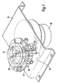
- the rotary valve comprises a body member 10 and a rotary actuator 12.
- the valve is mounted as shown in Figure 1 on a plate 15, beneath which is located a two directional drive comprising a motor 16 and a gearbox 18.
- the gearbox 18 incorporates a drive spindle 20 which extends through the valve body member 10 and is engageable with the actuator plate 12, to rotate the plate relative to the valve body.
- a spring is provided (not shown) to press the valve body and actuator together.
- the valve member is shown best in Figure 3 and it will be seen that the member comprises a planar face 21, having a central opening 23 for the drive shaft for the actuator plate and an aperture 22 for admission of pressurised air from a pump.
- the pump is not shown in the drawings, but would be connected to an air inlet 24 in one side of the body member.
- the planar surface 21 incorporates two diametrically opposed apertures 25 and 26, which are connected respectively to outlet ports 28 and 29 for connection to the first and second set of cells.
- the planar surface 21 also includes an arcuate slot 30 which can be arranged to supply other functions of the bed but, in this case, is not used.
- FIG. 3 Also shown in Figure 3 is an optical switch and receptor 32 which is connected to a connector pin 34, for linkage to a micro-processor.
- Figure 2 shows the actuator plate looking at the face 36 which is intended to be placed in face to face contact with the planar surface 21.
- Actuator plate 12 may be machined, e.g. from metal or plastic, or manufactured as a moulding.
- the actuator plate incorporates a recess 38 which forms a supply chamber for air to the valve.
- the plate also includes the port 40 for exhausting air from the two sets of cells.
- a series of indexing slots 42 Around the perimeter of the actuator plate is provided a series of indexing slots 42. As can be seen from the drawing, there are nine slots arranged at varying intervals around the perimeter.
- the actuator face 36 is in contact with the valve face 21, and is driven by the motor and gearbox 16,18 in one or other direction under the control of the micro-processor (not shown).
- the drive to the plate is arranged through the hub 44.
- the aperture 22 is always in communication with the supply chamber 38.
- air is supplied to one or other or both of the sets of valves.
- the apertures or slots 42 in the perimeter of the actuator face interact with the optical switch 32, in order that the control means can detect the position and hence the operating position of the actuator plate in the valve.
- the slots 42 around the perimeter of the actuator plate each correspond with an index point which represents a particular status with regard to the two groups of cells.
- the various index point positions are shown below.
- valve described above can be used in conjunction with any type of alternating pressure support system, one example being the mattress described in US Patent No. 5,396,671.
Landscapes
- Engineering & Computer Science (AREA)
- General Engineering & Computer Science (AREA)
- Mechanical Engineering (AREA)
- Health & Medical Sciences (AREA)
- Animal Behavior & Ethology (AREA)
- Life Sciences & Earth Sciences (AREA)
- Nursing (AREA)
- General Health & Medical Sciences (AREA)
- Public Health (AREA)
- Veterinary Medicine (AREA)
- Invalid Beds And Related Equipment (AREA)
- Valve-Gear Or Valve Arrangements (AREA)
- Multiple-Way Valves (AREA)
- Massaging Devices (AREA)
- Indication Of The Valve Opening Or Closing Status (AREA)
Abstract
Description
| Index Point | Cell A | Cell B |
| 1 | Fill | Fill |
| 2 | Fill | Hold inflated |
| 3 | Fill | Exhaust |
| 4 | Fill | Hold deflated |
| 5 | Fill | Fill |
| 6 | Hold inflated | Fill |
| 7 | Exhaust | Fill |
| 8 | Hold deflated | Fill |
Claims (5)
- A rotary valve for controlling air supply to an alternating pressure patient support system which comprises a body member (10) having a planar surface (21) and at least two apertures (25,26) for communication with cells or sets of cells in the patient support system, and a further aperture (22) for connection to a pressurised air source, an actuator member (12) which is rotatable in face to face contact with said planar surface, said actuator having a recessed portion (38) which forms an air supply chamber when in contact with said planar surface and is positioned to be constantly supplied with air from said further aperture, drive means (16,18) for rotating the actuator with respect to the first member and detector means (32) for detecting the position of the actuator relative to the body member and, in conjunction with control means, for controlling the timing and duration of air supply to the cells or sets of cells, characterised in that the drive means are capable of rotating the actuator in both directions.
- A valve as claimed in claim 1 wherein the actuator also includes an aperture through which air can be exhausted in turn from one or other of said cells or sets of cells.
- A valve as claimed in claim 1 or 2 in which the detector means comprises at least one optical sensor mounted in the vicinity of the actuator and arranged to detect the position of the actuator relative to the body member.
- A valve as claimed in claim 3 in which the sensor interacts with apertures or slots in the actuator.
- A patient support system having at least two inflatable cells or sets of cells wherein air supply to the cells is controlled by a rotary valve as claimed in any one of the preceding claims.
Applications Claiming Priority (3)
| Application Number | Priority Date | Filing Date | Title |
|---|---|---|---|
| GBGB9826133.2A GB9826133D0 (en) | 1998-11-27 | 1998-11-27 | Rotary valve |
| GB9826133 | 1998-11-27 | ||
| PCT/GB1999/003937 WO2000032149A1 (en) | 1998-11-27 | 1999-11-25 | Rotary valve |
Publications (3)
| Publication Number | Publication Date |
|---|---|
| EP1133270A1 EP1133270A1 (en) | 2001-09-19 |
| EP1133270B1 true EP1133270B1 (en) | 2005-04-06 |
| EP1133270B2 EP1133270B2 (en) | 2009-01-07 |
Family
ID=10843254
Family Applications (1)
| Application Number | Title | Priority Date | Filing Date |
|---|---|---|---|
| EP99956220A Expired - Lifetime EP1133270B2 (en) | 1998-11-27 | 1999-11-25 | Rotary valve |
Country Status (9)
| Country | Link |
|---|---|
| US (1) | US6571825B2 (en) |
| EP (1) | EP1133270B2 (en) |
| AT (1) | ATE292448T1 (en) |
| AU (1) | AU756860C (en) |
| CA (1) | CA2351342C (en) |
| DE (1) | DE69924635T3 (en) |
| ES (1) | ES2238857T5 (en) |
| GB (2) | GB9826133D0 (en) |
| WO (1) | WO2000032149A1 (en) |
Families Citing this family (31)
| Publication number | Priority date | Publication date | Assignee | Title |
|---|---|---|---|---|
| US6698046B1 (en) * | 2001-03-26 | 2004-03-02 | Sunflower Medical, L.L.C. | Air mattress control unit |
| GB0205924D0 (en) * | 2002-03-14 | 2002-04-24 | Huntleigh Technology Plc | Inflatable support |
| US7846141B2 (en) | 2002-09-03 | 2010-12-07 | Bluesky Medical Group Incorporated | Reduced pressure treatment system |
| GB0224986D0 (en) | 2002-10-28 | 2002-12-04 | Smith & Nephew | Apparatus |
| GB0325129D0 (en) | 2003-10-28 | 2003-12-03 | Smith & Nephew | Apparatus in situ |
| US8100887B2 (en) | 2004-03-09 | 2012-01-24 | Bluesky Medical Group Incorporated | Enclosure-based reduced pressure treatment system |
| US8062272B2 (en) | 2004-05-21 | 2011-11-22 | Bluesky Medical Group Incorporated | Flexible reduced pressure treatment appliance |
| US7909805B2 (en) | 2004-04-05 | 2011-03-22 | Bluesky Medical Group Incorporated | Flexible reduced pressure treatment appliance |
| US7776028B2 (en) | 2004-04-05 | 2010-08-17 | Bluesky Medical Group Incorporated | Adjustable overlay reduced pressure wound treatment system |
| US7708724B2 (en) | 2004-04-05 | 2010-05-04 | Blue Sky Medical Group Incorporated | Reduced pressure wound cupping treatment system |
| US10058642B2 (en) | 2004-04-05 | 2018-08-28 | Bluesky Medical Group Incorporated | Reduced pressure treatment system |
| US7998125B2 (en) | 2004-05-21 | 2011-08-16 | Bluesky Medical Group Incorporated | Hypobaric chamber treatment system |
| GB0424870D0 (en) * | 2004-11-10 | 2004-12-15 | Huntleigh Technology Plc | Rotary valve |
| ES2381020T3 (en) * | 2006-12-06 | 2012-05-22 | Rheavendors Services S.P.A. | Drink dispensing machine and operating method |
| FR2917278A1 (en) * | 2007-06-18 | 2008-12-19 | Hill Rom Ind S A Sa | MATTRESS-TYPE SUPPORT DEVICE HAVING A HETEROGENEUS INFLATABLE STRUCTURE |
| FR2922439B1 (en) * | 2007-10-18 | 2010-12-10 | Hill Rom Ind Sa | METHOD FOR ALTERNATE INFLATION OF AN INFLATABLE CELL SUPPORT DEVICE AND DEVICE FOR IMPLEMENTING IT |
| US8584286B2 (en) | 2010-04-27 | 2013-11-19 | Ec Service Inc. | Systems and methods for providing a self deflating cushion |
| US20120192954A1 (en) * | 2011-01-31 | 2012-08-02 | Red Lion Bio-Energy Technologies | Rotating disc valve |
| CN103083804B (en) * | 2011-11-07 | 2014-11-12 | 吴上能 | Control valve of air cushion bed |
| GB2503031A (en) * | 2012-06-15 | 2013-12-18 | Drake & Johnson Innovation Ltd | Hand Massage Device |
| US20140026326A1 (en) * | 2012-07-25 | 2014-01-30 | Richard N. Codos | Pressure adjustable platform system |
| US9801767B2 (en) * | 2013-03-14 | 2017-10-31 | Kap Medical, Inc. | Patient support apparatus and method |
| US9687413B2 (en) * | 2014-02-18 | 2017-06-27 | Covidien Lp | Compression garment inflation |
| US10660810B1 (en) | 2015-05-17 | 2020-05-26 | Thinair Surfaces Llc | Support apparatus and method with shear relief |
| CN206368786U (en) | 2016-12-08 | 2017-08-01 | 明达实业(厦门)有限公司 | The attachment structure of pump and aerated product |
| US10856668B2 (en) | 2017-04-10 | 2020-12-08 | Hill-Rom Services, Inc. | Mattress overlay control system with rotary valves and graphical user interface for percussion and vibration, turn assist and microclimate management |
| TWI727117B (en) * | 2017-11-13 | 2021-05-11 | 雃博股份有限公司 | Inflatable identification joint and its air bed system |
| CN208669644U (en) | 2018-05-16 | 2019-03-29 | 明达实业(厦门)有限公司 | A pump with multi-channel inflation and deflation function |
| EP3717782B1 (en) | 2017-11-27 | 2024-04-24 | Intex Marketing Ltd. | Manual inflation and deflation adjustment structure of a pump |
| TWI764059B (en) * | 2019-10-31 | 2022-05-11 | 雃博股份有限公司 | Air distribution device and air distribution method applied to patient support system |
| US12290484B2 (en) | 2021-06-30 | 2025-05-06 | Hill-Rom Services, Inc. | Manifold assembly for pneumatic system |
Family Cites Families (12)
| Publication number | Priority date | Publication date | Assignee | Title |
|---|---|---|---|---|
| NL261530A (en) * | 1960-03-01 | |||
| GB1595417A (en) * | 1977-03-29 | 1981-08-12 | Welch H G | Beds and mattresses |
| GB2124340A (en) * | 1982-05-08 | 1984-02-15 | John Whitford | A fluid delivery system and valve therefor |
| GB2164124A (en) * | 1984-09-04 | 1986-03-12 | Angar Scient Company Inc | Rotary valve |
| JPH0344187Y2 (en) * | 1987-11-10 | 1991-09-17 | ||
| GB8805961D0 (en) * | 1988-03-14 | 1988-04-13 | Huntleigh Technology Plc | Pressure controller |
| GB2243475B (en) * | 1990-04-26 | 1993-12-01 | David Theodore Nels Williamson | Improvements to gas and smoke alarm systems |
| EP0475593A1 (en) * | 1990-08-14 | 1992-03-18 | Medimatch Limited | Cushion |
| GB2290958B (en) * | 1992-03-09 | 1996-03-13 | Huntleigh Technology Plc | A pressure controlled inflatable pad apparatus |
| GB2275986B (en) * | 1993-03-12 | 1996-12-18 | Huntleigh Technology Plc | Adjustable pressure relief valve |
| GB9311069D0 (en) | 1993-05-23 | 1993-07-14 | British Astec Medical | Alternating pressure pad |
| US6058538A (en) * | 1998-10-07 | 2000-05-09 | Huntleigh Technology, Plc | Patient support |
-
1998
- 1998-11-27 GB GBGB9826133.2A patent/GB9826133D0/en not_active Ceased
-
1999
- 1999-11-25 AT AT99956220T patent/ATE292448T1/en active
- 1999-11-25 DE DE69924635T patent/DE69924635T3/en not_active Expired - Lifetime
- 1999-11-25 CA CA002351342A patent/CA2351342C/en not_active Expired - Fee Related
- 1999-11-25 GB GB9927891A patent/GB2344153B/en not_active Expired - Lifetime
- 1999-11-25 ES ES99956220T patent/ES2238857T5/en not_active Expired - Lifetime
- 1999-11-25 AU AU12863/00A patent/AU756860C/en not_active Ceased
- 1999-11-25 EP EP99956220A patent/EP1133270B2/en not_active Expired - Lifetime
- 1999-11-25 WO PCT/GB1999/003937 patent/WO2000032149A1/en not_active Ceased
-
2001
- 2001-05-25 US US09/866,522 patent/US6571825B2/en not_active Expired - Fee Related
Also Published As
| Publication number | Publication date |
|---|---|
| AU756860C (en) | 2003-08-07 |
| GB9826133D0 (en) | 1999-01-20 |
| DE69924635T2 (en) | 2005-09-15 |
| US20020121307A1 (en) | 2002-09-05 |
| EP1133270A1 (en) | 2001-09-19 |
| ATE292448T1 (en) | 2005-04-15 |
| AU756860B2 (en) | 2003-01-23 |
| EP1133270B2 (en) | 2009-01-07 |
| DE69924635D1 (en) | 2005-05-12 |
| AU1286300A (en) | 2000-06-19 |
| ES2238857T5 (en) | 2009-05-01 |
| GB2344153B (en) | 2003-07-30 |
| WO2000032149A1 (en) | 2000-06-08 |
| DE69924635T3 (en) | 2009-07-09 |
| GB9927891D0 (en) | 2000-01-26 |
| GB2344153A (en) | 2000-05-31 |
| US6571825B2 (en) | 2003-06-03 |
| ES2238857T3 (en) | 2005-09-01 |
| CA2351342C (en) | 2007-09-11 |
| CA2351342A1 (en) | 2000-06-08 |
Similar Documents
| Publication | Publication Date | Title |
|---|---|---|
| AU756860C (en) | Rotary valve | |
| USRE40511E1 (en) | Rotary disc valve | |
| EP0560563B1 (en) | A pressure controlled inflatable pad apparatus | |
| EP0429275A1 (en) | A fluid distributor, especially for a pressure wave mattress | |
| GB2208103A (en) | Bedsore-preventing air mattress controller | |
| US5277474A (en) | Cushion | |
| EP0688172A1 (en) | Pneumatic wheel chair cushion for reducing ischemic injury | |
| WO1999009860A2 (en) | Valve assembly | |
| GB2338033A (en) | Pressure control system | |
| GB1599422A (en) | Inflatable supports | |
| EP3815664B1 (en) | Patient support system with air distribution device and air distribution method for the patient support system | |
| JP4723748B2 (en) | Air distribution valve for pneumatic massager | |
| JPH0354735Y2 (en) | ||
| JPH07116199A (en) | Air mattress | |
| JP2716926B2 (en) | Rotary valve | |
| CA1087764A (en) | Inflatable supports | |
| JPS6021752A (en) | Air mat apparatus | |
| JPH0356434U (en) | ||
| JP3394579B2 (en) | Air mat air supply valve | |
| JP3141019B2 (en) | Air mat | |
| JP2002113060A (en) | Air massage machine | |
| GB2472819A (en) | A support with a layer of inflatable cells wherein different groups of cells can simultaneously be inflated or deflated | |
| CA2160996A1 (en) | Pneumatic wheel chair cushion for reducing ischemic injury | |
| JPH0788021A (en) | Air mat | |
| HK1003320B (en) | A pressure controlled inflatable pad apparatus |
Legal Events
| Date | Code | Title | Description |
|---|---|---|---|
| PUAI | Public reference made under article 153(3) epc to a published international application that has entered the european phase |
Free format text: ORIGINAL CODE: 0009012 |
|
| 17P | Request for examination filed |
Effective date: 20010528 |
|
| AK | Designated contracting states |
Kind code of ref document: A1 Designated state(s): AT BE CH CY DE DK ES FI FR GB GR IE IT LI LU MC NL PT SE |
|
| GRAP | Despatch of communication of intention to grant a patent |
Free format text: ORIGINAL CODE: EPIDOSNIGR1 |
|
| GRAS | Grant fee paid |
Free format text: ORIGINAL CODE: EPIDOSNIGR3 |
|
| GRAA | (expected) grant |
Free format text: ORIGINAL CODE: 0009210 |
|
| RAP1 | Party data changed (applicant data changed or rights of an application transferred) |
Owner name: KCI LICENSING, INC. |
|
| RBV | Designated contracting states (corrected) |
Designated state(s): AT BE CH CY DE DK ES FI FR GR IE IT LI LU MC NL PT SE |
|
| AK | Designated contracting states |
Kind code of ref document: B1 Designated state(s): AT BE CH CY DE DK ES FI FR GR IE IT LI LU MC NL PT SE |
|
| PG25 | Lapsed in a contracting state [announced via postgrant information from national office to epo] |
Ref country code: LI Free format text: LAPSE BECAUSE OF FAILURE TO SUBMIT A TRANSLATION OF THE DESCRIPTION OR TO PAY THE FEE WITHIN THE PRESCRIBED TIME-LIMIT Effective date: 20050406 Ref country code: FI Free format text: LAPSE BECAUSE OF FAILURE TO SUBMIT A TRANSLATION OF THE DESCRIPTION OR TO PAY THE FEE WITHIN THE PRESCRIBED TIME-LIMIT Effective date: 20050406 Ref country code: CH Free format text: LAPSE BECAUSE OF FAILURE TO SUBMIT A TRANSLATION OF THE DESCRIPTION OR TO PAY THE FEE WITHIN THE PRESCRIBED TIME-LIMIT Effective date: 20050406 Ref country code: BE Free format text: LAPSE BECAUSE OF FAILURE TO SUBMIT A TRANSLATION OF THE DESCRIPTION OR TO PAY THE FEE WITHIN THE PRESCRIBED TIME-LIMIT Effective date: 20050406 |
|
| REG | Reference to a national code |
Ref country code: CH Ref legal event code: EP |
|
| REG | Reference to a national code |
Ref country code: IE Ref legal event code: FG4D |
|
| REF | Corresponds to: |
Ref document number: 69924635 Country of ref document: DE Date of ref document: 20050512 Kind code of ref document: P |
|
| PG25 | Lapsed in a contracting state [announced via postgrant information from national office to epo] |
Ref country code: SE Free format text: LAPSE BECAUSE OF FAILURE TO SUBMIT A TRANSLATION OF THE DESCRIPTION OR TO PAY THE FEE WITHIN THE PRESCRIBED TIME-LIMIT Effective date: 20050706 Ref country code: GR Free format text: LAPSE BECAUSE OF FAILURE TO SUBMIT A TRANSLATION OF THE DESCRIPTION OR TO PAY THE FEE WITHIN THE PRESCRIBED TIME-LIMIT Effective date: 20050706 Ref country code: DK Free format text: LAPSE BECAUSE OF FAILURE TO SUBMIT A TRANSLATION OF THE DESCRIPTION OR TO PAY THE FEE WITHIN THE PRESCRIBED TIME-LIMIT Effective date: 20050706 |
|
| REG | Reference to a national code |
Ref country code: ES Ref legal event code: FG2A Ref document number: 2238857 Country of ref document: ES Kind code of ref document: T3 |
|
| PG25 | Lapsed in a contracting state [announced via postgrant information from national office to epo] |
Ref country code: PT Free format text: LAPSE BECAUSE OF FAILURE TO SUBMIT A TRANSLATION OF THE DESCRIPTION OR TO PAY THE FEE WITHIN THE PRESCRIBED TIME-LIMIT Effective date: 20050908 |
|
| REG | Reference to a national code |
Ref country code: CH Ref legal event code: PL |
|
| PG25 | Lapsed in a contracting state [announced via postgrant information from national office to epo] |
Ref country code: IE Free format text: LAPSE BECAUSE OF NON-PAYMENT OF DUE FEES Effective date: 20051125 Ref country code: CY Free format text: LAPSE BECAUSE OF FAILURE TO SUBMIT A TRANSLATION OF THE DESCRIPTION OR TO PAY THE FEE WITHIN THE PRESCRIBED TIME-LIMIT Effective date: 20051125 |
|
| PG25 | Lapsed in a contracting state [announced via postgrant information from national office to epo] |
Ref country code: MC Free format text: LAPSE BECAUSE OF NON-PAYMENT OF DUE FEES Effective date: 20051130 Ref country code: LU Free format text: LAPSE BECAUSE OF NON-PAYMENT OF DUE FEES Effective date: 20051130 |
|
| PLBI | Opposition filed |
Free format text: ORIGINAL CODE: 0009260 |
|
| PLAX | Notice of opposition and request to file observation + time limit sent |
Free format text: ORIGINAL CODE: EPIDOSNOBS2 |
|
| 26 | Opposition filed |
Opponent name: HUNTLEIGH TECHNOLOGY PLC Effective date: 20060106 |
|
| ET | Fr: translation filed | ||
| NLR1 | Nl: opposition has been filed with the epo |
Opponent name: HUNTLEIGH TECHNOLOGY PLC |
|
| PLAF | Information modified related to communication of a notice of opposition and request to file observations + time limit |
Free format text: ORIGINAL CODE: EPIDOSCOBS2 |
|
| PLAF | Information modified related to communication of a notice of opposition and request to file observations + time limit |
Free format text: ORIGINAL CODE: EPIDOSCOBS2 |
|
| REG | Reference to a national code |
Ref country code: IE Ref legal event code: MM4A |
|
| PLAF | Information modified related to communication of a notice of opposition and request to file observations + time limit |
Free format text: ORIGINAL CODE: EPIDOSCOBS2 |
|
| PLBB | Reply of patent proprietor to notice(s) of opposition received |
Free format text: ORIGINAL CODE: EPIDOSNOBS3 |
|
| PUAH | Patent maintained in amended form |
Free format text: ORIGINAL CODE: 0009272 |
|
| STAA | Information on the status of an ep patent application or granted ep patent |
Free format text: STATUS: PATENT MAINTAINED AS AMENDED |
|
| 27A | Patent maintained in amended form |
Effective date: 20090107 |
|
| AK | Designated contracting states |
Kind code of ref document: B2 Designated state(s): AT BE CH CY DE DK ES FI FR GR IE IT LI LU MC NL PT SE |
|
| NLR2 | Nl: decision of opposition |
Effective date: 20090107 |
|
| NLR3 | Nl: receipt of modified translations in the netherlands language after an opposition procedure | ||
| REG | Reference to a national code |
Ref country code: DE Ref legal event code: 8581 |
|
| REG | Reference to a national code |
Ref country code: ES Ref legal event code: DC2A Date of ref document: 20090224 Kind code of ref document: T5 |
|
| REG | Reference to a national code |
Ref country code: FR Ref legal event code: RN |
|
| REG | Reference to a national code |
Ref country code: FR Ref legal event code: IC |
|
| PGFP | Annual fee paid to national office [announced via postgrant information from national office to epo] |
Ref country code: DE Payment date: 20121121 Year of fee payment: 14 Ref country code: FR Payment date: 20121130 Year of fee payment: 14 |
|
| PGFP | Annual fee paid to national office [announced via postgrant information from national office to epo] |
Ref country code: ES Payment date: 20121212 Year of fee payment: 14 Ref country code: IT Payment date: 20121119 Year of fee payment: 14 |
|
| PGFP | Annual fee paid to national office [announced via postgrant information from national office to epo] |
Ref country code: AT Payment date: 20121029 Year of fee payment: 14 Ref country code: NL Payment date: 20121110 Year of fee payment: 14 |
|
| REG | Reference to a national code |
Ref country code: NL Ref legal event code: V1 Effective date: 20140601 |
|
| REG | Reference to a national code |
Ref country code: AT Ref legal event code: MM01 Ref document number: 292448 Country of ref document: AT Kind code of ref document: T Effective date: 20131125 |
|
| REG | Reference to a national code |
Ref country code: FR Ref legal event code: ST Effective date: 20140731 |
|
| PG25 | Lapsed in a contracting state [announced via postgrant information from national office to epo] |
Ref country code: AT Free format text: LAPSE BECAUSE OF NON-PAYMENT OF DUE FEES Effective date: 20131125 Ref country code: IT Free format text: LAPSE BECAUSE OF NON-PAYMENT OF DUE FEES Effective date: 20131125 Ref country code: DE Free format text: LAPSE BECAUSE OF NON-PAYMENT OF DUE FEES Effective date: 20140603 Ref country code: NL Free format text: LAPSE BECAUSE OF NON-PAYMENT OF DUE FEES Effective date: 20140601 |
|
| REG | Reference to a national code |
Ref country code: DE Ref legal event code: R119 Ref document number: 69924635 Country of ref document: DE Effective date: 20140603 |
|
| PG25 | Lapsed in a contracting state [announced via postgrant information from national office to epo] |
Ref country code: FR Free format text: LAPSE BECAUSE OF NON-PAYMENT OF DUE FEES Effective date: 20131202 |
|
| REG | Reference to a national code |
Ref country code: ES Ref legal event code: FD2A Effective date: 20150430 |
|
| PG25 | Lapsed in a contracting state [announced via postgrant information from national office to epo] |
Ref country code: ES Free format text: LAPSE BECAUSE OF NON-PAYMENT OF DUE FEES Effective date: 20131126 |