EP1133262B1 - A surgical device for closing tissue - Google Patents
A surgical device for closing tissue Download PDFInfo
- Publication number
- EP1133262B1 EP1133262B1 EP99954206A EP99954206A EP1133262B1 EP 1133262 B1 EP1133262 B1 EP 1133262B1 EP 99954206 A EP99954206 A EP 99954206A EP 99954206 A EP99954206 A EP 99954206A EP 1133262 B1 EP1133262 B1 EP 1133262B1
- Authority
- EP
- European Patent Office
- Prior art keywords
- surgical device
- shaft
- cap
- tissue
- distal end
- Prior art date
- Legal status (The legal status is an assumption and is not a legal conclusion. Google has not performed a legal analysis and makes no representation as to the accuracy of the status listed.)
- Expired - Lifetime
Links
Images


Classifications
-
- A—HUMAN NECESSITIES
- A61—MEDICAL OR VETERINARY SCIENCE; HYGIENE
- A61B—DIAGNOSIS; SURGERY; IDENTIFICATION
- A61B17/00—Surgical instruments, devices or methods
- A61B17/064—Surgical staples, i.e. penetrating the tissue
-
- A—HUMAN NECESSITIES
- A61—MEDICAL OR VETERINARY SCIENCE; HYGIENE
- A61B—DIAGNOSIS; SURGERY; IDENTIFICATION
- A61B17/00—Surgical instruments, devices or methods
- A61B17/56—Surgical instruments or methods for treatment of bones or joints; Devices specially adapted therefor
- A61B17/58—Surgical instruments or methods for treatment of bones or joints; Devices specially adapted therefor for osteosynthesis, e.g. bone plates, screws or setting implements
- A61B17/68—Internal fixation devices, including fasteners and spinal fixators, even if a part thereof projects from the skin
- A61B17/84—Fasteners therefor or fasteners being internal fixation devices
- A61B17/86—Pins or screws or threaded wires; nuts therefor
- A61B17/8605—Heads, i.e. proximal ends projecting from bone
-
- A—HUMAN NECESSITIES
- A61—MEDICAL OR VETERINARY SCIENCE; HYGIENE
- A61B—DIAGNOSIS; SURGERY; IDENTIFICATION
- A61B17/00—Surgical instruments, devices or methods
- A61B17/04—Surgical instruments, devices or methods for suturing wounds; Holders or packages for needles or suture materials
- A61B17/0401—Suture anchors, buttons or pledgets, i.e. means for attaching sutures to bone, cartilage or soft tissue; Instruments for applying or removing suture anchors
- A61B2017/0412—Suture anchors, buttons or pledgets, i.e. means for attaching sutures to bone, cartilage or soft tissue; Instruments for applying or removing suture anchors having anchoring barbs or pins extending outwardly from suture anchor body
-
- A—HUMAN NECESSITIES
- A61—MEDICAL OR VETERINARY SCIENCE; HYGIENE
- A61B—DIAGNOSIS; SURGERY; IDENTIFICATION
- A61B17/00—Surgical instruments, devices or methods
- A61B17/04—Surgical instruments, devices or methods for suturing wounds; Holders or packages for needles or suture materials
- A61B17/0401—Suture anchors, buttons or pledgets, i.e. means for attaching sutures to bone, cartilage or soft tissue; Instruments for applying or removing suture anchors
- A61B2017/0427—Suture anchors, buttons or pledgets, i.e. means for attaching sutures to bone, cartilage or soft tissue; Instruments for applying or removing suture anchors having anchoring barbs or pins extending outwardly from the anchor body
-
- A—HUMAN NECESSITIES
- A61—MEDICAL OR VETERINARY SCIENCE; HYGIENE
- A61B—DIAGNOSIS; SURGERY; IDENTIFICATION
- A61B17/00—Surgical instruments, devices or methods
- A61B17/04—Surgical instruments, devices or methods for suturing wounds; Holders or packages for needles or suture materials
- A61B17/0401—Suture anchors, buttons or pledgets, i.e. means for attaching sutures to bone, cartilage or soft tissue; Instruments for applying or removing suture anchors
- A61B2017/0464—Suture anchors, buttons or pledgets, i.e. means for attaching sutures to bone, cartilage or soft tissue; Instruments for applying or removing suture anchors for soft tissue
-
- A—HUMAN NECESSITIES
- A61—MEDICAL OR VETERINARY SCIENCE; HYGIENE
- A61B—DIAGNOSIS; SURGERY; IDENTIFICATION
- A61B17/00—Surgical instruments, devices or methods
- A61B17/064—Surgical staples, i.e. penetrating the tissue
- A61B2017/0646—Surgical staples, i.e. penetrating the tissue for insertion into cartillege, e.g. meniscus
-
- A—HUMAN NECESSITIES
- A61—MEDICAL OR VETERINARY SCIENCE; HYGIENE
- A61B—DIAGNOSIS; SURGERY; IDENTIFICATION
- A61B17/00—Surgical instruments, devices or methods
- A61B17/064—Surgical staples, i.e. penetrating the tissue
- A61B2017/0647—Surgical staples, i.e. penetrating the tissue having one single leg, e.g. tacks
-
- A—HUMAN NECESSITIES
- A61—MEDICAL OR VETERINARY SCIENCE; HYGIENE
- A61F—FILTERS IMPLANTABLE INTO BLOOD VESSELS; PROSTHESES; DEVICES PROVIDING PATENCY TO, OR PREVENTING COLLAPSING OF, TUBULAR STRUCTURES OF THE BODY, e.g. STENTS; ORTHOPAEDIC, NURSING OR CONTRACEPTIVE DEVICES; FOMENTATION; TREATMENT OR PROTECTION OF EYES OR EARS; BANDAGES, DRESSINGS OR ABSORBENT PADS; FIRST-AID KITS
- A61F2/00—Filters implantable into blood vessels; Prostheses, i.e. artificial substitutes or replacements for parts of the body; Appliances for connecting them with the body; Devices providing patency to, or preventing collapsing of, tubular structures of the body, e.g. stents
- A61F2/02—Prostheses implantable into the body
- A61F2/08—Muscles; Tendons; Ligaments
- A61F2/0811—Fixation devices for tendons or ligaments
Definitions
- This invention concerns a surgical device, and particularly but not exclusively a surgical device for closing torn or incised soft bodily tissue.
- US-A-5 013 316 discloses a surgical device comprising a shaft, a hollow cap at the proximal end of the shaft, and a plurality of tissue engagement formations on the shaft.
- the distal end of the shaft may be provided with a sharp tip, which may be enlarged relative to the shaft.
- the distal end of the shaft may be blunt, and may be rounded.
- the cap is preferably arranged such that in use it contacts the surface of the tissue substantially circumferentially even when the shaft is inserted other than normally to the tissue surface.
- the cap may have a substantially frusto conical shape with the shaft being attached to the proximal smaller end thereof.
- One or more openings may be provided extending partway up the side walls of the cap from the distal larger end thereof.
- the engagement formations are preferably provided at a 120° or less spacing around the shaft.
- the formations may be provided in a plurality of groups of formations, with each group spaced longitudinally from each other on the shaft.
- the formations are preferably circumferentially equispaced.
- the formations may be in the form of barbs, which are preferably rearwardly pointing.
- Engagement formations may be provided on or adjacent the distal end of the shaft.
- the shaft preferably has a uniform cross-section along its length from the distal end to the cap.
- the shaft cross-section may be circular, elliptical or polygonal, and especially triangular or square.
- the cross-section may have a plurality of circumferential lobes, which lobes are desirably equispaced.
- the cap preferably comprises a formation engageable with a surgical tool, and the formation is preferably provided on the proximal end of the cap, and may comprise a recess or projection.
- the formation is preferably such as to permit the device to be used arthroscopically.
- the device is preferably made of a resorbable material, and desirably includes a resorbable polymer or copolymer.
- the polymer or copolymer may be from the range of bioabsorbable polymers including ⁇ -hydroxybutyrate (hydroxybutanoate), hydroxyvalerate (hydroxypentanoate), lactic acid (2-hydroxypropanoic acid) or glycolic acid (2-hydroxyethanoic acid).
- the resorbable material is preferably a composite and also comprises a particulate or fibrous solid material.
- the solid material may comprise any of hydroxyapatite, tri-calcium phosphate, calcium carbonate, calcium sulphate, magnesium oxide or bioactive glass
- Figs. 1-5 show a surgical device 10 suitable for use for closing tears, wounds and incisions in bodily tissue, and is particularly suited to the repair of torn menisci in the knee.
- the device 10 comprises a shaft 12 which has a basic circular cross-section with four equispaced circumferential lobes 14 extending therefrom.
- the shaft 10 is provided with a sharp point 16 at its distal end.
- a plurality of tissue engagement formations are provided on the shaft 12 in the form of barbs 18.
- the barbs 18 are provided on sleeves 19 which intimately fit on the shaft 12, and the barbs 18 are provided on the lobes 14.
- a cap 20 is provided on the proximal end of the shaft 12 and the cap has a hollow frusto conical configuration pointing away from the distal end, with a dome 22 of a smaller diameter provided on the proximal end thereof.
- the dome 22 is engageable with a pusher or other tool to permit the device to be arthroscopically inserted.
- Figs. 2-4 shows an upper part of the device 10 being inserted into bodily tissue 24.
- the bottom edge of the cap 20 is just engaging against the top surface of the tissue 24.
- the device 10 has been pushed further in causing the bottom edge of the cap 20 to deform outwardly.
- the bottom edge of the cap 20 has entered the tissue but due to the construction of the head can only enter a relatively short distance.
- Fig. 5 illustrates the condition where the shaft 12 has been inserted into the tissue 24 at an inclined angle. In this instance the cap 20 deforms to provide a circumferential engagement with the tissue 24.
- the device 10 therefore provides a good circumferential engagement with the surface of the tissue or engaging slightly into the tissue irrespective of whether the shaft is normally inserted thereinto. If movement of the tissue occurs as a result of movement of the body, this can be accommodated by the cap so as to maintain circumferential engagement throughout the movement yet permitting movement to occur.
- the device 10 is made of polylactide which will resorb within the body thus eliminating the need for further surgery to remove the device and also preventing the risk of long term infection which a non-absorbable device would present.
- Other bioabsorbable polymers such as polyglycolide or polydioxanone are suitable materials for this device.
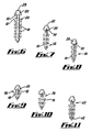
- Figs. 6-12 show further devices according to the invention.
- a device 26 is shown.
- the shaft 12 of the device 26 has an ellipsoidal cross-section, and two sets of six barbs 18 are provided on opposite sides of the shaft 12.
- the cap 20 is a similar shape to that provided on the device 10 except that a recess 28 is provided instead of a dome to engage with a pusher.
- a split 30 is provided extending partway up the edge of the cap 20 to permit further flexing of the cap.
- Fig. 7 shows a device 32 of triangular cross-section with three sets of three barbs 18 mounted on each of the faces of the triangular cross-section.
- the cap 20 is provided with a dome 22 and also a split 30.
- Fig. 8 shows a further device 34 which is similar to the device 32 except that the barbs 18 are provided on the apices of the cross-section, and three equispaced splits 30 are provided in the cap 20.
- Fig. 9 shows a smaller device 36 of circular cross-section with four barbs 18 equispaced around the shaft 12 adjacent the distal end thereof.
- the cap 20 of the device 36 is similar to that of the device 32.
- Fig. 10 shows a device 38 of square cross-section with two barbs 18 on each face of the shaft 12.
- Fig. 11 shows a further device 40 which is similar to the device 32 except that an enlarged distal head 42 is provided.
- Fig. 12 shows a still further surgical device 44.
- the device 44 has a similar configuration of barbs 46 to the device 10, but each barb 46 is mounted separately on the shaft 48.
- the cap 50 is similar to the cap 20.
- the distal end 52 of the shaft 48 is in contrast rounded.
- the rounded end 52 means that the device 44 is not self-penetrating and therefore a tract would initially require to be made in the tissue.
- a rounded end has the advantage of causing less tissue irritation than usually occurs with a pointed end.
Landscapes
- Health & Medical Sciences (AREA)
- Life Sciences & Earth Sciences (AREA)
- Surgery (AREA)
- Heart & Thoracic Surgery (AREA)
- Engineering & Computer Science (AREA)
- Biomedical Technology (AREA)
- Nuclear Medicine, Radiotherapy & Molecular Imaging (AREA)
- Medical Informatics (AREA)
- Molecular Biology (AREA)
- Animal Behavior & Ethology (AREA)
- General Health & Medical Sciences (AREA)
- Public Health (AREA)
- Veterinary Medicine (AREA)
- Surgical Instruments (AREA)
- Materials For Medical Uses (AREA)
Abstract
Description
Claims (29)
- A surgical device for closing bodily tissue, the device comprising a shaft (12, 48) which can be inserted into the tissue, a hollow cap (20, 50) at the proximal end of the shaft (12, 48) which is engageable substantially against the surface of the tissue, and a plurality of tissue engagement formations (18,46) on the shaft (12, 48) to prevent the device from being withdrawn from the tissue, characterised in that the cap (20, 50) is flexible so that a good circumferential engagement with the surface of the tissue is provided.
- A surgical device according to claim 1, characterised in that the distal end of the shaft (12, 48) is provided with a sharp tip (16).
- A surgical device according to claim 1, characterised in that the distal end (52) of the shaft (12, 48) is blunt.
- A surgical device according to claim 3, characterised in that the distal end (52) of the shaft (12, 48) is rounded.
- A surgical device according to any of the preceding claims, characterised in that the distal end (52) is enlarged relative to the shaft (12, 48).
- A surgical device according to any of the preceding claims, characterised in that the cap (20, 50) is arranged such that in use the cap (20, 50) contacts the surface of the tissue substantially circumferentially even when the shaft (12, 48) is inserted other than normally to the tissue surface.
- A surgical device according to any of the preceding claims, characterised in that the cap (20, 50) has a substantially frusto conical shape with the shaft (12, 48) being attached to the proximal smaller end thereof.
- A surgical device according to claim 7, characterised in that one or more openings (30) may be provided extending partway up the side walls of the cap (20, 50) from the distal larger end thereof.
- A surgical device according to any of the preceding claims, characterised in that the engagement formations (18,46) are provided at a 120° or less spacing around the shaft (12, 48).
- A surgical device according to any of the preceding claims, characterised in that the engagement formations (18,46) are provided in a plurality of groups of formations, with each group spaced longitudinally from each other on the shaft (12, 48).
- A surgical device according to any of the preceding claims, characterised in that the engagement formations (18,46) are circumferentially equispaced.
- A surgical device according to any of the preceding claims, characterised in that the engagement formations are in the form of barbs (18, 46).
- A surgical device according to claim 12, characterised in that the barbs (18, 46) are rearwardly pointing.
- A surgical device according any of the preceding claims, characterised in that engagement formations (18,46) are provided on or adjacent to the distal end (52) of the shaft (12, 48).
- A surgical device according any of the preceding claims, characterised in that the shaft (12, 48) has a uniform cross-section along its length from the distal end (52).
- A surgical device according any of the preceding claims, characterised in that the shaft (12, 48) cross-section is circular, elliptical or polygonal.
- A surgical device according any of the preceding claims, characterised in that the shaft (12, 48) cross-section is triangular or square.
- A surgical device according any of the preceding claims, characterised in that the shaft (12, 48) cross-section has a plurality of circumferential lobes (14).
- A surgical device according to claim 18, characterised in that the lobes (14) are equispaced.
- A surgical device according any of the preceding claims, characterised in that the cap (20, 50) comprises a formation (22) engageable with a surgical tool.
- A surgical device according to claim 20, characterised in that the formation (22) is provided on the proximal end of the cap (20, 50).
- A surgical device according to claim 20 or 21, characterised in that the cap (20, 50) comprises a recess (28) or projection (22).
- A surgical device according to any of claims 20 to 22, characterised in that the formation (22) is shaped such as to permit the device to be used arthroscopically.
- A surgical device according any of the preceding claims, characterised in that the device is made of a resorbable material.
- A surgical device according to claim 24, characterised in that the resorbable material includes a resorbable polymer or copolymer.
- A surgical device according to claim 25, characterised in that the polymer or copolymer is from the range of bioabsorbable polymers including β-hydroxybutyrate (hydroxybutanoate), hydroxyvalerate (hydroxypentanoate), lactic acid (2-hydroxypropanoic acid) or glycolic acid (2-hydroxyethanoic acid).
- A surgical device according to any of claims 24 to 26, characterised in that the resorbable material is a composite.
- A surgical device according to claim 27, characterised in that the composite comprises a particulate or fibrous solid material.
- A surgical device according to claim 28, characterised in that the solid material comprises any of hydroxyapatite, tri-calcium phosphate, calcium carbonate, calcium sulphate, magnesium oxide or bioactive glass.
Applications Claiming Priority (3)
| Application Number | Priority Date | Filing Date | Title |
|---|---|---|---|
| GB9825681 | 1998-11-25 | ||
| GBGB9825681.1A GB9825681D0 (en) | 1998-11-25 | 1998-11-25 | Surgical device |
| PCT/GB1999/003744 WO2000030552A1 (en) | 1998-11-25 | 1999-11-10 | A surgical device for closing tissue |
Publications (2)
| Publication Number | Publication Date |
|---|---|
| EP1133262A1 EP1133262A1 (en) | 2001-09-19 |
| EP1133262B1 true EP1133262B1 (en) | 2002-09-18 |
Family
ID=10842928
Family Applications (1)
| Application Number | Title | Priority Date | Filing Date |
|---|---|---|---|
| EP99954206A Expired - Lifetime EP1133262B1 (en) | 1998-11-25 | 1999-11-10 | A surgical device for closing tissue |
Country Status (7)
| Country | Link |
|---|---|
| EP (1) | EP1133262B1 (en) |
| AT (1) | ATE224167T1 (en) |
| AU (1) | AU1062400A (en) |
| DE (1) | DE69903062T2 (en) |
| ES (1) | ES2183616T3 (en) |
| GB (2) | GB9825681D0 (en) |
| WO (1) | WO2000030552A1 (en) |
Families Citing this family (9)
| Publication number | Priority date | Publication date | Assignee | Title |
|---|---|---|---|---|
| US20020169452A1 (en) * | 2001-05-14 | 2002-11-14 | Pertti Tormala | Minimally traumatic surgical device for tissue treatment |
| WO2003034925A2 (en) * | 2001-10-23 | 2003-05-01 | Tyco Healthcare Group Lp | Surgical fasteners |
| EP1765218B1 (en) * | 2004-06-14 | 2014-06-11 | Boston Scientific Limited | An implantable sling for treating urinary incontinence |
| US8545866B2 (en) | 2004-10-29 | 2013-10-01 | Smith & Nephew, Inc. | Bioabsorbable polymers |
| ATE424862T1 (en) * | 2004-10-29 | 2009-03-15 | Smith & Nephew Inc | BIOABSORBABLE POLYMERS WITH CALCIUM CARBONATE |
| DE102004053464A1 (en) * | 2004-11-03 | 2006-05-04 | Karl Storz Gmbh & Co. Kg | Oval pin for fixing a loaded under tensile load implant |
| US10779811B2 (en) * | 2014-12-11 | 2020-09-22 | Smith & Nephew, Inc. | Bone anchor having improved fixation strength |
| CN106999181A (en) * | 2014-12-11 | 2017-08-01 | 史密夫和内修有限公司 | Suture anchor with reinforcement with ribbing |
| CN110151240A (en) * | 2019-05-07 | 2019-08-23 | 张为 | Annulus fibrosus disci intervertebralis crackle suture instrument |
Family Cites Families (3)
| Publication number | Priority date | Publication date | Assignee | Title |
|---|---|---|---|---|
| US5013316A (en) * | 1990-03-26 | 1991-05-07 | Marlowe Goble E | Soft tissue anchor system |
| FI95537C (en) * | 1992-01-24 | 1996-02-26 | Biocon Oy | Surgical implant |
| US5827298A (en) * | 1995-11-17 | 1998-10-27 | Innovasive Devices, Inc. | Surgical fastening system and method for using the same |
-
1998
- 1998-11-25 GB GBGB9825681.1A patent/GB9825681D0/en not_active Ceased
-
1999
- 1999-11-10 EP EP99954206A patent/EP1133262B1/en not_active Expired - Lifetime
- 1999-11-10 WO PCT/GB1999/003744 patent/WO2000030552A1/en not_active Ceased
- 1999-11-10 AU AU10624/00A patent/AU1062400A/en not_active Abandoned
- 1999-11-10 GB GB0115479A patent/GB2363990A/en not_active Withdrawn
- 1999-11-10 AT AT99954206T patent/ATE224167T1/en not_active IP Right Cessation
- 1999-11-10 ES ES99954206T patent/ES2183616T3/en not_active Expired - Lifetime
- 1999-11-10 DE DE69903062T patent/DE69903062T2/en not_active Expired - Fee Related
Also Published As
| Publication number | Publication date |
|---|---|
| ATE224167T1 (en) | 2002-10-15 |
| GB9825681D0 (en) | 1999-01-20 |
| DE69903062D1 (en) | 2002-10-24 |
| EP1133262A1 (en) | 2001-09-19 |
| AU1062400A (en) | 2000-06-13 |
| WO2000030552A1 (en) | 2000-06-02 |
| ES2183616T3 (en) | 2003-03-16 |
| GB0115479D0 (en) | 2001-08-15 |
| GB2363990A (en) | 2002-01-16 |
| DE69903062T2 (en) | 2003-01-23 |
Similar Documents
| Publication | Publication Date | Title |
|---|---|---|
| EP0525352B1 (en) | Resorbable fixation device with controlled stiffness for treating bodily material in vivo and introducer therefor | |
| EP0625887B1 (en) | Polymeric screws and coatings for surgical uses | |
| US6423062B2 (en) | Bioabsorbable pin for external bone fixation | |
| EP1437968B1 (en) | Surgical fasteners | |
| EP0993273B1 (en) | Surgical fastener for tissue treatment | |
| US5562704A (en) | Surgical implant | |
| US20090228021A1 (en) | Matrix material | |
| US9414876B2 (en) | Composite fixation device | |
| US10213195B2 (en) | Medical fixation devices with improved torsional drive head | |
| US5500000A (en) | Soft tissue repair system and method | |
| US9655610B2 (en) | Methods and systems for medializing a turbinate | |
| US20040230195A1 (en) | Soft-tissue screw | |
| JP2003153916A (en) | Absorbent bone anchor | |
| EP1133262A1 (en) | A surgical device for closing tissue | |
| US20020161371A1 (en) | Fixative device | |
| CN108066041B (en) | Absorbable nails and repair fixators |
Legal Events
| Date | Code | Title | Description |
|---|---|---|---|
| PUAI | Public reference made under article 153(3) epc to a published international application that has entered the european phase |
Free format text: ORIGINAL CODE: 0009012 |
|
| 17P | Request for examination filed |
Effective date: 20010518 |
|
| AK | Designated contracting states |
Kind code of ref document: A1 Designated state(s): AT BE CH CY DE DK ES FI FR GB GR IE IT LI LU MC NL PT SE |
|
| AX | Request for extension of the european patent |
Free format text: AL;LT;LV;MK;RO;SI |
|
| GRAG | Despatch of communication of intention to grant |
Free format text: ORIGINAL CODE: EPIDOS AGRA |
|
| GRAG | Despatch of communication of intention to grant |
Free format text: ORIGINAL CODE: EPIDOS AGRA |
|
| GRAG | Despatch of communication of intention to grant |
Free format text: ORIGINAL CODE: EPIDOS AGRA |
|
| GRAH | Despatch of communication of intention to grant a patent |
Free format text: ORIGINAL CODE: EPIDOS IGRA |
|
| 17Q | First examination report despatched |
Effective date: 20020125 |
|
| GRAH | Despatch of communication of intention to grant a patent |
Free format text: ORIGINAL CODE: EPIDOS IGRA |
|
| GRAA | (expected) grant |
Free format text: ORIGINAL CODE: 0009210 |
|
| AK | Designated contracting states |
Kind code of ref document: B1 Designated state(s): AT BE CH CY DE DK ES FI FR GB GR IE IT LI LU MC NL PT SE |
|
| PG25 | Lapsed in a contracting state [announced via postgrant information from national office to epo] |
Ref country code: NL Free format text: LAPSE BECAUSE OF FAILURE TO SUBMIT A TRANSLATION OF THE DESCRIPTION OR TO PAY THE FEE WITHIN THE PRESCRIBED TIME-LIMIT Effective date: 20020918 Ref country code: LI Free format text: LAPSE BECAUSE OF FAILURE TO SUBMIT A TRANSLATION OF THE DESCRIPTION OR TO PAY THE FEE WITHIN THE PRESCRIBED TIME-LIMIT Effective date: 20020918 Ref country code: GR Free format text: LAPSE BECAUSE OF FAILURE TO SUBMIT A TRANSLATION OF THE DESCRIPTION OR TO PAY THE FEE WITHIN THE PRESCRIBED TIME-LIMIT Effective date: 20020918 Ref country code: CH Free format text: LAPSE BECAUSE OF FAILURE TO SUBMIT A TRANSLATION OF THE DESCRIPTION OR TO PAY THE FEE WITHIN THE PRESCRIBED TIME-LIMIT Effective date: 20020918 Ref country code: BE Free format text: LAPSE BECAUSE OF FAILURE TO SUBMIT A TRANSLATION OF THE DESCRIPTION OR TO PAY THE FEE WITHIN THE PRESCRIBED TIME-LIMIT Effective date: 20020918 Ref country code: AT Free format text: LAPSE BECAUSE OF FAILURE TO SUBMIT A TRANSLATION OF THE DESCRIPTION OR TO PAY THE FEE WITHIN THE PRESCRIBED TIME-LIMIT Effective date: 20020918 |
|
| REF | Corresponds to: |
Ref document number: 224167 Country of ref document: AT Date of ref document: 20021015 Kind code of ref document: T |
|
| REG | Reference to a national code |
Ref country code: GB Ref legal event code: FG4D |
|
| REG | Reference to a national code |
Ref country code: CH Ref legal event code: EP |
|
| REG | Reference to a national code |
Ref country code: IE Ref legal event code: FG4D |
|
| REF | Corresponds to: |
Ref document number: 69903062 Country of ref document: DE Date of ref document: 20021024 |
|
| PG25 | Lapsed in a contracting state [announced via postgrant information from national office to epo] |
Ref country code: LU Free format text: LAPSE BECAUSE OF NON-PAYMENT OF DUE FEES Effective date: 20021110 |
|
| PG25 | Lapsed in a contracting state [announced via postgrant information from national office to epo] |
Ref country code: IE Free format text: LAPSE BECAUSE OF NON-PAYMENT OF DUE FEES Effective date: 20021111 |
|
| PG25 | Lapsed in a contracting state [announced via postgrant information from national office to epo] |
Ref country code: CY Free format text: LAPSE BECAUSE OF FAILURE TO SUBMIT A TRANSLATION OF THE DESCRIPTION OR TO PAY THE FEE WITHIN THE PRESCRIBED TIME-LIMIT Effective date: 20021130 |
|
| PG25 | Lapsed in a contracting state [announced via postgrant information from national office to epo] |
Ref country code: DK Free format text: LAPSE BECAUSE OF FAILURE TO SUBMIT A TRANSLATION OF THE DESCRIPTION OR TO PAY THE FEE WITHIN THE PRESCRIBED TIME-LIMIT Effective date: 20021218 |
|
| PG25 | Lapsed in a contracting state [announced via postgrant information from national office to epo] |
Ref country code: PT Free format text: LAPSE BECAUSE OF FAILURE TO SUBMIT A TRANSLATION OF THE DESCRIPTION OR TO PAY THE FEE WITHIN THE PRESCRIBED TIME-LIMIT Effective date: 20021219 |
|
| ET | Fr: translation filed | ||
| NLV1 | Nl: lapsed or annulled due to failure to fulfill the requirements of art. 29p and 29m of the patents act | ||
| REG | Reference to a national code |
Ref country code: ES Ref legal event code: FG2A Ref document number: 2183616 Country of ref document: ES Kind code of ref document: T3 |
|
| REG | Reference to a national code |
Ref country code: CH Ref legal event code: PL |
|
| PG25 | Lapsed in a contracting state [announced via postgrant information from national office to epo] |
Ref country code: MC Free format text: LAPSE BECAUSE OF NON-PAYMENT OF DUE FEES Effective date: 20030601 |
|
| PLBE | No opposition filed within time limit |
Free format text: ORIGINAL CODE: 0009261 |
|
| STAA | Information on the status of an ep patent application or granted ep patent |
Free format text: STATUS: NO OPPOSITION FILED WITHIN TIME LIMIT |
|
| REG | Reference to a national code |
Ref country code: IE Ref legal event code: MM4A |
|
| 26N | No opposition filed |
Effective date: 20030619 |
|
| PGFP | Annual fee paid to national office [announced via postgrant information from national office to epo] |
Ref country code: GB Payment date: 20041022 Year of fee payment: 6 |
|
| PGFP | Annual fee paid to national office [announced via postgrant information from national office to epo] |
Ref country code: SE Payment date: 20041123 Year of fee payment: 6 |
|
| PGFP | Annual fee paid to national office [announced via postgrant information from national office to epo] |
Ref country code: FR Payment date: 20041126 Year of fee payment: 6 |
|
| PGFP | Annual fee paid to national office [announced via postgrant information from national office to epo] |
Ref country code: DE Payment date: 20041127 Year of fee payment: 6 |
|
| PGFP | Annual fee paid to national office [announced via postgrant information from national office to epo] |
Ref country code: FI Payment date: 20041129 Year of fee payment: 6 |
|
| PGFP | Annual fee paid to national office [announced via postgrant information from national office to epo] |
Ref country code: ES Payment date: 20041213 Year of fee payment: 6 |
|
| PG25 | Lapsed in a contracting state [announced via postgrant information from national office to epo] |
Ref country code: IT Free format text: LAPSE BECAUSE OF NON-PAYMENT OF DUE FEES Effective date: 20051110 Ref country code: FI Free format text: LAPSE BECAUSE OF NON-PAYMENT OF DUE FEES Effective date: 20051110 |
|
| PG25 | Lapsed in a contracting state [announced via postgrant information from national office to epo] |
Ref country code: SE Free format text: LAPSE BECAUSE OF NON-PAYMENT OF DUE FEES Effective date: 20051111 Ref country code: ES Free format text: LAPSE BECAUSE OF NON-PAYMENT OF DUE FEES Effective date: 20051111 |
|
| PG25 | Lapsed in a contracting state [announced via postgrant information from national office to epo] |
Ref country code: DE Free format text: LAPSE BECAUSE OF NON-PAYMENT OF DUE FEES Effective date: 20060601 |
|
| REG | Reference to a national code |
Ref country code: FR Ref legal event code: CA |
|
| EUG | Se: european patent has lapsed | ||
| GBPC | Gb: european patent ceased through non-payment of renewal fee |
Effective date: 20051110 |
|
| PG25 | Lapsed in a contracting state [announced via postgrant information from national office to epo] |
Ref country code: FR Free format text: LAPSE BECAUSE OF NON-PAYMENT OF DUE FEES Effective date: 20060731 |
|
| REG | Reference to a national code |
Ref country code: FR Ref legal event code: ST Effective date: 20060731 |
|
| REG | Reference to a national code |
Ref country code: ES Ref legal event code: FD2A Effective date: 20051111 |