EP1133200A2 - Array antenna receiving apparatus - Google Patents
Array antenna receiving apparatus Download PDFInfo
- Publication number
- EP1133200A2 EP1133200A2 EP01105576A EP01105576A EP1133200A2 EP 1133200 A2 EP1133200 A2 EP 1133200A2 EP 01105576 A EP01105576 A EP 01105576A EP 01105576 A EP01105576 A EP 01105576A EP 1133200 A2 EP1133200 A2 EP 1133200A2
- Authority
- EP
- European Patent Office
- Prior art keywords
- calibration
- signals
- antenna elements
- power levels
- output
- Prior art date
- Legal status (The legal status is an assumption and is not a legal conclusion. Google has not performed a legal analysis and makes no representation as to the accuracy of the status listed.)
- Granted
Links
Images


Classifications
-
- H—ELECTRICITY
- H01—ELECTRIC ELEMENTS
- H01Q—ANTENNAS, i.e. RADIO AERIALS
- H01Q21/00—Antenna arrays or systems
-
- H—ELECTRICITY
- H01—ELECTRIC ELEMENTS
- H01Q—ANTENNAS, i.e. RADIO AERIALS
- H01Q3/00—Arrangements for changing or varying the orientation or the shape of the directional pattern of the waves radiated from an antenna or antenna system
- H01Q3/26—Arrangements for changing or varying the orientation or the shape of the directional pattern of the waves radiated from an antenna or antenna system varying the relative phase or relative amplitude of energisation between two or more active radiating elements; varying the distribution of energy across a radiating aperture
- H01Q3/267—Phased-array testing or checking devices
Definitions
- the present inventions relates to an array antenna receiving apparatus for removing interference by controlling directivity of an antenna, and especially, to an array antenna receiving apparatus for conducting calibration of a plurality of radio receiving sections.
- a method of forming a reception directivity pattern in which, using an array antenna receiving apparatus consisting of a plurality of antenna elements, a reception gain is increased for a direction along which a desired signal comes, and a reception gain is decreased for interference from other users and interference due to a delay wave.
- amplitude and phase information for compensation is obtained by inputting known calibration signals to each radio receiving section and measuring an amplitude variation and a phase variation.
- Fig. 6 is a block diagram showing one arrangement example of a conventional array antenna receiving apparatus for conducting calibration.
- this conventional example is constructed of an array antenna 601 consisting of a plurality of antenna elements 602-1 to 602-N, multiplex circuits 603-1 to 603-N for multiplying calibration signals by signals received at the antenna elements 602-1 to 602-N and outputting them, which are provided in accordance with the antenna elements 602-1 to 602-N, respectively, radio receiving sections 604-1 to 604-N for conducting reception processing of signals output from the multiplex circuits 603-1 to 603-N, which are provided in accordance with the antenna elements 602-1 to 602-N, respectively, a detection circuit 611 to which signals output from the radio receiving sections 604-1 to 604-N are input, for detecting amplitude information and phase information of the signals received at the antenna elements 602-1 to 602-N based on the input signals, user signal processing sections 605-1 to 605-M, provided by the number of users, for correcting the signals output from the radio receiving sections 604-1 to 604-N using the amplitude information and phase information detected at the detection circuit 611, and
- the antenna elements 602-1 to 602-N constituting the array antenna 601 restrictions are not especially imposed on directivity within a horizontal plane and a perpendicular plane for a single antenna element, and for example, omini (non-directivity) and dipole (dipole directivity) can be given.
- the antenna elements 602-1 to 602-N are placed so that reception signals of the respective antenna elements 602-1 to 602-N have a correlation with each other, and receive signals in which desired signals and a plurality of interference signals are multiplied.
- the calibration signals output from the power level variable circuit 609 are multiplied by the signals received at the antenna elements 602-1 to 602-N in a radio band by means of code multiplexing and so forth for example, and are output to the radio receiving sections 604-1 to 604-N.
- a multiplexing method here is not limited to the code multiplexing.
- the calibration signals multiplied at the multiplex circuits 603-1 to 603-N can be extracted.
- the radio receiving sections 604-1 to 604-N are constructed of a low-noise amplifier, a band-limitation filter, a mixer, a local dial device, an AGC (Auto Gain Controller), a quadrature detector, a low band pass filter, an analog/digital converter and so forth.
- a signal output from the multiplex circuit 603-N is input thereto, and amplification, frequency conversion from a radio band to a base band, quadrature detection, analog/digital conversion and so forth of the input signal are conducted, and the signal is output to the user signal processing sections 605-1 to 605-M and the detection circuit 611.
- an AGC that is a non-linear circuit is used.
- signals output from the radio receiving sections 604-1 to 604-N are input thereto, and calibration signals are extracted from the input signals, and thereby, amplitude and phase information of the signals received at the antenna elements 602-1 to 602-N is detected.
- the detected amplitude and phase information is output to the signal processing sections 605-1 to 605-M.
- the amplitude and phase information of the signals received at the antenna elements 602-1 to 602-N is detected by investigating variation quantity of amplitude and phase of the calibration signals in the radio receiving sections 604-1 to 604-N.
- the signals output from the radio receiving sections 604-1 to 604-N and the amplitude and phase information detected at the detection circuit 611 are input thereto, and the signals output from the radio receiving sections 604-1 to 604-N are corrected based on the amplitude and phase information detected at the detection circuit 611, and thereby, a reception directivity pattern is formed such that, for each user, a reception gain is increased for a direction along which a user signal comes, and a reception gain is decreased for interference from other users and interference due to a delay wave, and demodulation signals received by means of the reception directivity pattern are output.
- calibration signals are generated in a base band, and the generated calibration signals are output to the radio transmitting section 608 for calibration.
- the calibration signals in the base band which were output from the signal generator 607 for calibration, are input thereto, and digital/analog conversion, frequency conversion from a base band to a radio band and so forth are applied to the input calibration signals, and these calibration signals are output to the power level variable circuit 609 as calibration signals having a frequency band same as the signals received at the antenna elements 602-1 to 602-N.
- the calibration signals output from the radio transmitting section 608 for calibration are output to the multiplex circuits 603-1 to 603-N at arbitrary power levels.
- a desired (user) signal component and an interference signal component, and a thermal noise are included. Further, multi-path components are included in the desired signal component and the interference signal component, respectively. Usually, those signal components come from directions different from each other.
- the respective signal components which come from directions different from each other are distinguished from each other, and a reception directivity pattern is formed.
- the calibration signals having a frequency band same as the signals received at the antenna elements 602-1 to 602-N are multiplied by the reception signals, and in the detection circuit 611, the calibration signals are extracted from the signals output from the radio receiving sections 604-1 to 604-N, and amplitude and phase information of the reception signals is detected based on a variation of the amplitude and phase of those calibration signals, and thereby, correction is applied to the amplitude and phase information of the reception signals input to the user signal processing sections 605-1 to 605-M.
- the calibration signals of the respective outputs from the radio receiving sections 604-1 to 604-N are extracted while power levels of the calibration signals are changed by means of the power level variable circuit 609, amplitude and phase information of the reception signals is detected based on a variation of the amplitude and phase of those calibration signals, and thereby, correction quantity to be applied to the amplitude and phase information of the reception signals input to the user signal processing sections 605-1 to 605-M is determined for every power level of each calibration signal.
- the array antenna receiving apparatus having such calibration means, even though the amplitude and phase of the reception signals are changed inside the radio receiving sections 604-1 to 604-N when the array antenna receiving apparatus works, the amplitude and phase information of the reception signals input to the user signal processing sections 605-1 to 605-M can be corrected. Also, when the apparatus does not work, calibration can be conducted with high accuracy in accordance with the power levels of the reception signals.
- the power levels of the reception signals are changed in time for each antenna element.
- the calibration signals input to the respective radio receiving sections are compared with the calibration signals included in the signals output from the respective radio receiving sections, and thereby, amplitude and phase variations of the calibration signals in the respective radio receiving sections are detected, and based on this detection result, amplitude and phase information of the signals received at the antenna elements 602-1 to 602-N is detected.
- the present invention is made to solve the above-mentioned problems.
- An objective of the present invention is to provide an array antenna receiving apparatus capable of conducting calibration with high accuracy even in an operation.
- an array antenna receiving apparatus of the present invention has an array antenna consisting of N (N is an integer more than or equal to 1) antenna elements, N radio receiving sections for conducting reception processing of signals received at the above-described antenna elements, calibration means for multiplying calibration signals by the signals received at the above-described antenna elements, extracting the above-described calibration signals from signals output from the above-described radio receiving sections, and detecting amplitude and phase information of the signals received at the above-described antenna elements based on the extracted calibration signals, and M (M is an integer more than or equal to 1) user signal processing sections for correcting the signals output from the above-described radio receiving sections based on the amplitude and phase information detected at the above-described calibration means, and outputting them as demodulation signals, and it is characterized in that the above-described calibration means multiplies the above-described calibration signals by the signals received at the above-described antenna elements at power levels determined based on power levels of the signals output from the above-described radio receiving sections.
- the above-described calibration means is characterized in that it has:
- the above-described calibration means is characterized in that it has:
- the above-described signal processing section for calibration is characterized in that it outputs the control signals such that the power levels of the calibration signals extracted from the signals output from the above-described radio receiving sections becomes to be constant.
- the above-described signal processing section for calibration is characterized in that it recognizes a ratio of the signals output from the above-described radio receiving sections and the calibration signals extracted from the above-described signals using a bit error rate of the calibration signals extracted from the signals output from the above-described radio receiving sections.
- an array antenna receiving apparatus has an array antenna consisting of N (N is an integer more than or equal to 1) antenna elements, N radio receiving sections for conducting reception processing of signals received at the above-described antenna elements, calibration means for multiplying calibration signals by the signals received at the above-described antenna elements, extracting the above-described calibration signals from signals output from the above-described radio receiving sections, and detecting amplitude and phase information of the signals received at the above-described antenna elements based on the extracted calibration signals, and M (M is an integer more than or equal to 1) user signal processing sections for correcting the signals output from the above-described radio receiving sections based on the amplitude and phase information detected at the above-described calibration means, and outputting them as demodulation signals, and
- the above-described calibration means multiplies the above-described calibration signals by the signals received at the above-described antenna elements at power levels determined based on power levels of the signals received at the above-described antenna elements.
- the above-described calibration means is characterized in that it has:
- the above-described calibration means is characterized in that it has:
- the above-described signal processing section for calibration is characterized in that it outputs the control signals such that a ratio of the power levels of the signals received at the above-described antenna elements and the power levels of the calibration signals output from the above-described power level variable circuits becomes to be constant.
- an array antenna receiving apparatus has an array antenna consisting of N (N is an integer more than or equal to 1) antenna elements, N radio receiving sections for conducting reception processing of signals received at the above-described antenna elements, calibration means for multiplying calibration signals by the signals received at the above-described antenna elements, extracting the above-described calibration signals from signals output from the above-described radio receiving sections, and detecting amplitude and phase information of the signals received at the above-described antenna elements based on the extracted calibration signals, and M (M is an integer more than or equal to 1) user signal processing sections for correcting the signals output from the above-described radio receiving sections based on the amplitude and phase information detected at the above-described calibration means, and outputting them as demodulation signals, and
- an array antenna receiving apparatus has an array antenna consisting of N (N is an integer more than or equal to 1) antenna elements, N radio receiving sections for conducting reception processing of signals received at the above-described antenna elements, calibration means for multiplying calibration signals by the signals received at the above-described antenna elements, extracting the above-described calibration signals from signals output from the above-described radio receiving sections, and detecting amplitude and phase information of the signals received at the above-described antenna elements based on the extracted calibration signals, and M (M is an integer more than or equal to 1) user signal processing sections for correcting the signals output from the above-described radio receiving sections based on the amplitude and phase information detected at the above-described calibration means, and outputting them as demodulation signals, and it is characterized in that the above-described calibration means has:
- the above-described signal processing section for calibration is characterized in that it outputs the control signals such that a ratio of the power levels of the signals output from the above-described multiplex circuits and the power levels of the calibration signals output from the above-described power level variable circuits becomes to be constant.
- the array antenna receiving apparatus is characterized in that
- the calibration signals to be multiplied by the signals received at the antenna elements are multiplied by the signals received at the antenna elements at the power levels such that the power levels of the calibration signals extracted from the signals output from the radio receiving section become constant, even in case that the power levels of the signals received at the antenna elements change in time, and in the radio receiving sections, output thereof are automatically controlled so that a sum of the power levels of the signals received at the antenna elements and the power levels of the calibration signals become constant, the power levels of the calibration signals extracted at the calibration means do not become unfixed, and thereby, in the calibration means, the amplitude and phase variations of the calibration signals in the radio receiving section are exactly detected, and in association therewith, the amplitude and phase information of the signals received at the antenna elements is exactly detected. Thereby, calibration is conducted with high accuracy even in an operation.
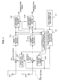
- Fig. 1 is a block diagram showing the first embodiment of an array antenna receiving apparatus of the present invention.
- this embodiment is constructed of an array antenna 101 consisting of N (N is an integer more than or equal to 1) antenna elements 102-1 to 102-N, multiplex circuits 103-1 to 103-N for multiplying calibration signals by signals received at the antenna elements 102-1 to 102-N and outputting them, which are provided in accordance with the antenna elements 102-1 to 102-N, respectively, radio receiving sections 104-1 to 104-N for conducting reception processing of signals output from the multiplex circuits 103-1 to 103-N, which are provided in accordance with the antenna elements 102-1 to 102-N, respectively, a signal processing section 106 for calibration, to which signals output from the radio receiving sections 104-1 to 104-N are input, and which detects amplitude information and phase information of the signals received at the antenna elements 102-1 to 102-N based on the input signals, M (M is an integer more than or equal to 1)user signal processing sections 105-1 to 105-M, provided by the number of users, for correcting the signals output from the radio receiving
- calibration means is constructed of the multiplex circuits 103-1 to 103-N, the signal processing section 106 for calibration, the signal generator 107 for calibration, the radio transmitting section 108 for calibration, and the power level variable circuits 109-1 to 109-N.
- the antenna elements 102-1 to 102-N constituting the array antenna 101 restrictions are not especially imposed on directivity within a horizontal plane and a perpendicular plane for a single antenna element, and for example, omini (non-directivity) and dipole (dipole directivity) can be given.
- the antenna elements 102-1 to 102-N are placed so that reception signals of the respective antenna elements 102-1 to 102-N have a correlation with each other, and receive signals in which desired signals and a plurality of interference signals are multiplied.
- the calibration signals output from the power level variable circuits 109-1 to 109-N are multiplied by the signals received at the antenna elements 102-1 to 102-N in a radio band, and are output to the radio receiving sections 104-1 to 104-N.
- a multiplexing method in the multiplex circuits 103-1 to 103-N there is no limitation on a multiplexing method in the multiplex circuits 103-1 to 103-N, and for example, code multiplexing is given.
- code multiplexing a power adder that operates in a radio band can be used for the multiplex circuits 103-1 to 103-N.
- the radio receiving sections 104-1 to 104-N are constructed of a low-noise amplifier, a band-limitation filter, a mixer, a local dial device, an AGC (Auto Gain Controller), a quadrature detector, a low band pass filter, an analog/digital converter and so forth.
- a signal output from the multiplex circuit 103-N is input thereto, and amplification, frequency conversion from a radio band to a base band, quadrature detection, analog/digital conversion and so forth of the input signal are conducted, and the signal is output to the user signal processing sections 105-1 to 105-M and the signal processing section 106 for calibration.
- an AGC that is anon-linear circuit is used for each of the radio receiving sections 104-1 to 104-N.
- the signals output from the radio receiving sections 104-1 to 104-N and the amplitude and phase information detected at the signal processing section 106 for calibration are input thereto, and the signals output from the radio receiving sections 104-1 to 104-N are corrected based on the amplitude and phase information detected at the signal processing section 106 for calibration, and thereby, a reception directivity pattern is formed such that, for each user, a reception gain is increased for a direction along which a user signal comes , and a reception gain is decreased for interference from other users and interference due to a delay wave, and demodulation signals received by means of the reception directivity pattern are output.
- the user signal processing sections 105-1 to 105-N there is no limitation on their arrangements, algorithm for forming the reception directivity pattern, and a method of conducting a correction to the signals output from the radio receiving sections 104-1 to 104-N by using the amplitude and phase information detected at the signal processing section 106 for calibration.
- signals output from the radio receiving sections 104-1 to 104-N are input thereto, and calibration signals are extracted from the input signals, and thereby, amplitude and phase information of the signals received at the antenna elements 102-1 to 102-N is detected.
- the detected amplitude and phase information is output to the signal processing sections 105-1 to 105-M.
- the amplitude and phase information of the signals received at the antenna elements 102-1 to 102-N is detected by investigating variation quantity of amplitude and phase of the calibration signals in the radio receiving sections 104-1 to 104-N.
- control signals for controlling power of the calibration signals input to the multiplex circuits 103-1 to 103-N are output to the power level variable circuits 109-1 to 109-N so that a ratio of power levels of the signals output from the radio receiving sections 104-1 to 104-N and power levels of the calibration signals input to the multiplex circuits 103-1 to 103-N is made constant.
- the power levels of the signals to be output are automatically controlled by means of the AGC within each of the radio receiving sections 104-1 to 104-N so as to become constant independent of the power levels of the signals to be input to the radio receiving sections 104-1 to 104-N. Accordingly, the power levels of the calibration signals included in the signals output from the respective radio receiving sections 104-1 to 104-N become constant, and amplitude and phase variations of the calibration signals in the respective radio receiving sections 104-1 to 104-N can be exactly detected in the calibration signal processing section 106, and in association therewith, amplitude and phase information of the signals received at the antenna elements 102-1 to 102-N can be exactly detected.
- calibration signals are extracted from the signals output from the respective radio receiving sections 104-1 to 104-N, and the extracted calibration signals are compared with the calibration signals to be input to the multiplex circuits 103-1 to 103-N, and based on a comparison result, amplitude and phase information of the calibration signals in the respective radio receiving sections 104-1 to 104-N is detected, and based on a result of this detection, amplitude and phase information of the signals received at the antenna elements 102-1 to 102-N is detected.
- control signals are output to the power level variable circuits 109 so that the power levels of the calibration signals extracted from the signals output from the radio receiving sections 104-1 to 104-N are made constant.
- bit error rate Bit Error Rate
- the calibration signal is known, it is possible to measure a BER of the calibration signals in the signal processing section 106 for calibration.
- the BER is large, it is shown that, compared with the power levels of the signals output from the radio receiving sections 104-1 to 104-N, the power levels of the calibration signals extracted from the signals output from the radio receiving sections 104-1 to 104-N are smaller, and also, in case that the BER is small, it is shown that, compared with the power levels of the signals output from the radio receiving sections 104-1 to 104-N, the power levels of the calibration signals extracted from the signals output from the radio receiving sections 104-1 to 104-N are larger.
- a ratio of the power levels of the signals output from the radio receiving sections 104-1 to 104-N and the power levels of the calibration signals extracted from the signals output from the radio receiving sections 104-1 to 104-N can be approximately calculated.
- calibration signals are generated in a base band, and the generated calibration signals are output to the radio transmitting section 108 for calibration.
- the calibration signals in the base band which were output from the signal generator 107 for calibration, are input thereto, and digital/analog conversion, frequency conversion from a base band to a radio band and so forth are applied to the input calibration signals, and these calibration signals are output to the power level variable circuits 109 as calibration signals having a frequency band same as the signals received at the antenna elements 102-1 to 102-N.
- the calibration signals output from the radio transmitting section 108 for calibration are output to the multiplex circuits 103-1 to 103-N at power levels based on the control signals output from the signal processing section 106 for calibration.
- the calibration signals having power levels in accordance with the power levels of the signals received at the respective antenna elements 102-1 - 102-N are supplied to the respective radio receiving sections 104-1 to 104-N, even though the power levels of the reception signals change in time, and the outputs are automatically controlled by means of the AGCs within the respective radio receiving sections 104-1 to 104-N so that a sum of the power levels of the reception signals and the power levels of the calibration signals become constant, the power levels of the calibration signals included in the signals output from the respective radio receiving sections 104-1 to 104-N can be kept constant, and in the signal processing section 106 for calibration, amplitude and phase variations of the calibration signals in the respective radio receiving sections 104-1 to 104-N can be exactly detected, and in association therewith, the amplitude and phase information of the signals received at the antenna elements 102-1 to 102-N is exactly detected. Thereby, calibration can be conducted with high accuracy even in an operation.
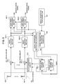
- Fig. 2 is a block diagram showing the second embodiment of an array antenna receiving apparatus of the present invention.
- this embodiment is constructed of an array antenna 201 consisting of a plurality of antenna elements 202-1 to 202-N, multiplex circuits 203-1 to 203-N for multiplying calibration signals by signals received at the antenna elements 202-1 to 202-N and outputting them, which are provided in accordance with the antenna elements 202-1 to 202-N, respectively, radio receiving sections 204-1 to 204-N for conducting reception processing of signals output from the multiplex circuits 203-1 to 203-N, which are provided in accordance with the antenna elements 202-1 to 202-N, respectively, a signal processing section 206 for calibration, to which the signals received at the antenna elements 202-1 to 202-N and signals output from the radio receiving sections 204-1 to 204-N are input, and which detects amplitude information and phase information of the signals received at the antenna elements 202-1 to 202-N based on the signals output from the radio receiving sections 204-1 to 204-N, user signal processing sections 205-1 to 205-M, provided by the number of users,
- this embodiment is the same as the first embodiment other than the signal processing section 206 for calibration.
- the signals received at the antenna elements 202-1 to 202-N and the signals output from the radio receiving sections 204-1 to 204-N are input thereto, and calibration signals are extracted from the signals output from the radio receiving sections 204-1 to 204-N, and thereby, amplitude and phase information of the signals received at the antenna elements 202-1 to 202-N is detected.
- the detected amplitude and phase information is output to the user signal processing sections 205-1 to 205-N.
- the amplitude and phase information of the signals received at the antenna elements 202-1 to 202-N is detected by investigating variation quantity of amplitude and phase of the calibration signals in the radio receiving sections 204-1 to 204-N.
- control signals for controlling power of the calibration signals input to the multiplex circuits 203-1 to 203-N are output to the power level variable circuits 209-1 to 209-N so that a ratio of power levels of the signals received at the antenna elements 202-1 to 202-N and power levels of the calibration signals input to the multiplex circuits 203-1 to 203-N is made constant.
- the power levels of the signals output from the radio receiving sections are measured, and based on these power levels, power of the calibration signals to be input to the multiplex circuits is controlled, the power levels of the reception signals in the antenna elements 202-1 to 202-1 are measured, and based on these power levels, power of the calibration signals to be input to the multiplex circuits 203-1 to 203-N is controlled, and accordingly, information before the signals received at the antenna elements 202-1 to 202-N are multiplied by the calibration signals can be used in the multiplex circuits 203-1 to 203-N, and calibration can be conducted with higher accuracy.
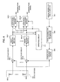
- Fig. 3 is a block diagram showing the third embodiment of an array antenna receiving apparatus of the present invention.
- this embodiment is constructed of an array antenna 301 consisting of a plurality of antenna elements 302-1 to 302-N, multiplex circuits 303-1 to 303-N for multiplying calibration signals by signals received at the antenna elements 302-1 to 302-N and outputting them, which are provided in accordance with the antenna elements 302-1 to 302-N, respectively, radio receiving sections 304-1 to 304-N for conducting reception processing of signals output from the multiplex circuits 303-1 to 303-N, which are provided in accordance with the antenna elements 302-1 to 302-N, respectively, a signal processing section 306 for calibration, to which the signals output from the multiplex circuits 303-1 to 303-N and signals output from the radio receiving sections 304-1 to 304-Nare input, and which detects amplitude information and phase information of the signals received at the antenna elements 302-1 to 302-N based on the signals output from the radio receiving sections 304-1 to 304-N, user signal processing sections 305-1 to 305-M, provided by the number of users, for correct
- this embodiment is the same as the first embodiment other than the signal processing section 306 for calibration.
- the signals output from the multiplex circuits 303-1 to 303-N and the signals output from the radio receiving sections 304-1 to 304-N are input thereto, and calibration signals are extracted from the signals output from the radio receiving sections 304-1 to 304-N, and thereby, amplitude and phase information of the signals received at the antenna elements 302-1 to 302-N is detected.
- the detected amplitude and phase information is output to the user signal processing sections 305-1 to 305-N.
- the amplitude and phase information of the signals received at the antenna elements 302-1 to 302-N is detected by investigating variation quantity of amplitude and phase of the calibration signals in the radio receiving sections 304-1 to 304-N.
- control signals for controlling power of the calibration signals to be input to the multiplex circuits 303-1 to 303-N are output to the power level variable circuits 309-1 to 309-N so that a ratio of the power levels of the signals output from the multiplex circuits 303-1 to 303-N and the power levels of the calibration signals input to the multiplex circuits 303-1 to 303-N is made constant.
- the power levels of the signals received at the respective antenna elements 302-1 to 302-N can be calculated by subtracting the power levels of the calibration signals input to the multiplex circuits 303-1 to 303-N from the power levels of the signals output from the multiplex circuits 303-1 to 303-N, it is understood that this embodiment is the same as the second embodiment in principle.
- the power levels of the signals received at the respective antenna elements are measured, and based on these power levels, power of the calibration signals to be input to the multiplex circuits is controlled, the power levels of the signals output from the multiplex circuits 303-1 to 303-N, that is, the power levels of the input signals in the respective radio receiving sections 304-1 to 304-N are measured, and based on these power levels, power of the calibration signals to be input to the multiplex circuits 303-1 to 303-N is controlled.
- Fig. 4 is a block diagram showing the fourth embodiment of an array antenna receiving apparatus of the present invention.
- this embodiment is constructed of an array antenna 401 consisting of a plurality of antenna elements 402-1 to 402-N, multiplex circuits 403-1 to 403-N for multiplying calibration signals by signals received at the antenna elements 402-1 to 402-N and outputting them, which are provided in accordance with the antenna elements 402-1 to 402-N, respectively, radio receiving sections 404-1 to 404-N including AGCs (Auto Gain Controllers) that are automatic gain controlling means, for conducting reception processing of signals output from the multiplex circuits 403-1 to 403-N and outputting amplification factors in the AGCs as AGC control information, which are provided in accordance with the antenna elements 402-1 to 402-N, respectively, a signal processing section 406 for calibration, to which the AGC control information output from the radio receiving sections 404-1 to 404-N and signals output from the radio receiving sections 404-1 to 404-N are input, and which detects amplitude information and phase information of the signals received at the antenna elements 402-1 to 402-N based on the signals output
- AGCs Automatic
- this embodiment is the same as the first embodiment other than the radio receiving sections 404-1 to 404-N and the signal processing section 406 for calibration.
- the radio receiving sections 404-1 to 404-N are constructed of a low-noise amplifier, a band-limitation filter, a mixer, a local dial device, an AGC (Auto Gain Controller), a quadrature detector, a low band pass filter, an analog/digital converter and so forth.
- a signal output from the multiplex circuit 403-N is input thereto, and amplification, frequency conversion from a radio band to a base band, quadrature detection, analog/digital conversion and so forth of the input signal are conducted, and the signal is output to the user signal processing sections 405-1 to 405-M and the signal processing section 406 for calibration.
- AGC amplification factors in the AGCs provided within the respective radio receiving sections 404-1 to 404-N are output to the signal processing section 406 for calibration as control information.
- the AGC control information output from the radio receiving sections 404-1 to 404-N and the signals output from the radio receiving sections 404-1 to 404-N are input thereto, and calibration signals are extracted from the signals output from the radio receiving sections 404-1 to 404-N, and thereby, amplitude and phase information of the signals received at the antenna elements 402-1 to 402-N is detected, and the detected amplitude and phase information is output to the user signal processing sections 405-1 to 405-N.
- power levels of signals to be input to the radio receiving sections 404-1 to 404-N are approximately calculated, and control signals for controlling power of the calibration signals to be input to the multiplex circuits 403-1 to 403-N are output to the power level variable circuits 409-1 to 409-N so that a ratio of the power levels of the signals input to the radio receiving sections 404-1 to 404-N and the power levels of the calibration signals input to the radio receiving sections 404-1 to 404-N is made constant.
- the AGC control information output from the radio receiving sections 404-1 to 404-N is information such that, in accordance with the power levels of the signals to be input to the radio receiving sections 404-1 to 404-N, in case that the input power levels are small, amplification factors of the AGCs are increased, and in case that the input power levels are large, the amplification factors of the AGCs are decreased, based on the power levels of the signals and the AGC control information which were output from the radio receiving sections 404-1 to 404-N, the power levels of the signals to be input to the radio receiving sections 404-1 to 404-N can be approximately calculated.
- this embodiment is the same as the third embodiment.
- the output power levels of the multiplex circuits that is, the power levels of the signals to be input to the respective radio receiving sections are measured, and based on these power levels, power of the calibration signals to be input to the multiplex circuits is controlled, only the AGC control information output from the radio receiving sections 404-1 to 404-N is used. Since this AGC control information is a base band signal, a load of the signal processing section for calibration can be reduced compared with the third embodiment in which the input signals of the respective radio receiving sections are handled, which are direct radio band signals.
- Fig. 5 is a block diagram showing the fifth embodiment of an array antenna receiving apparatus of the present invention.
- this embodiment is constructed of an array antenna 501 consisting of a plurality of antenna elements 502-1 to 502-N, multiplex circuits 503-1 to 503-N for multiplying calibration signals by signals received at the antenna elements 502-1 to 502-N and outputting them, which are provided in accordance with the antenna elements 502-1 to 502-N, respectively, radio receiving sections 504-1 to 504-N for conducting reception processing of signals output from the multiplex circuits 503-1 to 503-N, which are provided in accordance with the antenna elements 502-1 to 502-N, respectively, a signal processing section 506 for calibration, to which the signals output from the radio receiving sections 504-1 to 504-N are input, and which detects amplitude information and phase information of the signals received at the antenna elements 502-1 to 502-N based on the input signals, user signal processing sections 505-1 to 505-M, provided by the number of users, for correcting the signals output from the radio receiving sections 504-1 to 504-N using the amplitude information and phase information detected at the signal
- this embodiment is the same as the first embodiment other than the power level variable circuits 509-1 to 509-K and the selection/branch circuit 510.
- the calibration signals output from the radio transmitting section 508 for calibration and having a frequency band same as the signals received at the antenna elements 502-1 to 502-N are input thereto, and these calibration signals are output to the selection/distribution circuit 510 at arbitrary power levels based on control of the signal processing section 506 for calibration.
- the calibration signals output from the power level variable circuits 509-1 to 509-K are input thereto, and selection and distribution of these calibration signals are conducted, and they are output to the multiplex circuits 503-1 to 503-N.
- the number of the selection and distribution and a manner of connection in the selection/distribution circuit 510 there is no limitation on the number of the selection and distribution and a manner of connection in the selection/distribution circuit 510. Particularly, an arrangement by means of one power level variable circuit and one input and N outputs distributor can be given.
- the arrangement of the array antenna receiving apparatus can be simplified.
- CDMA code division multiplex coupling
- the element number of the antenna and the placement of the antenna elements there is no limitation on the element number of the antenna and the placement of the antenna elements, and as an example of the placement of the antenna elements, a straight line placement having a half wavelength interval of a carrier wave can be given.
- the calibration signals to be multiplied by the signals received at the antenna elements are multiplied by the signals received at the antenna elements at the power levels such that the power levels of the calibration signals extracted from the signals output from the radio receiving section become constant, even in case that the power levels of the signals received at the antenna elements change in time, and in the radio receiving sections, output thereof are automatically controlled so that a sum of the power levels of the signals received at the antenna elements and the power levels of the calibration signals become constant, calibration can be conducted with high accuracy.
Landscapes
- Variable-Direction Aerials And Aerial Arrays (AREA)
- Radio Transmission System (AREA)
Abstract
Description
it is characterized in that the above-described calibration means multiplies the above-described calibration signals by the signals received at the above-described antenna elements at power levels determined based on power levels of the signals output from the above-described radio receiving sections.
it is characterized in that the above-described calibration means has:
Claims (18)
- An array antenna receiving apparatus comprising:an array antenna consisting of N (N is an integer more than or equal to 1) antenna elements,N radio receiving sections for conducting reception processing of signals received at said antenna elements,calibration means for multiplying calibration signals by the signals received at said antenna elements, extracting said calibration signals from signals output from said radio receiving sections, and detecting amplitude and phase information of the signals received at said antenna elements based on the extracted calibration signals, andM (M is an integer more than or equal to 1) user signal processing sections for correcting the signals output from said radio receiving sections based on the amplitude and phase information detected at said calibration means, and outputting them as demodulation signals;wherein said calibration means multiplies said calibration signals by the signals received at said antenna elements at power levels determined based on power levels of the signals output from said radio receiving sections.
- An array antenna receiving apparatus recited in claim 1, wherein said calibration means comprises:N multiplex circuits for multiplying calibration signals by the signals received at said antenna elements;a signal generator for calibration, which generates said calibration signals;a signal radio transmitting section for calibration, which applies frequency conversion to the calibration signals generated at said signal generator for calibration and outputs the calibration signals having a frequency band same as a frequency of the signals received at said antenna elements;a signal processing section for calibration, which extracts said calibration signals from the signals output from said radio receiving sections, detects amplitude and phase information of the signals received at said antenna elements based on the extracted calibration signals, and outputs control signals for controlling power levels of said calibration signals based on power levels of the signals output from said radio receiving sections; andN power level variable circuits for outputting the calibration signals output from said signal radio transmitting section for calibration at power levels based on the control signals output from said signal processing section for calibration, andthe calibration signals output from said power level variable circuits are multiplied by the signals received at said antenna elements in said multiplex circuits.
- An array antenna receiving apparatus recited in claim 2, wherein said signal processing section for calibration comprises means for outputting the control signals such that the power levels of the calibration signals extracted from the signals output from said radio receiving sections becomes to be constant.
- An array antenna receiving apparatus recited in claim 3, wherein said signal processing section for calibration comprises means for recognizing a ratio of the signals output from said radio receiving sections and the calibration signals extracted from said signals using a bit error rate of the calibration signals extracted from the signals output from said radio receiving sections.
- An array antenna receiving apparatus recited in claim 1, wherein said calibration means comprises:N multiplex circuits for multiplying calibration signals by the signals received at said antenna elements;a signal generator for calibration, which generates said calibration signals;a signal radio transmitting section for calibration, which applies frequency conversion to the calibration signals generated at said signal generator for calibration and outputs the calibration signals having a frequency band same as a frequency of the signals received at said antenna elements;a signal processing section for calibration, which extracts said calibration signals from the signals output from said radio receiving sections, detects amplitude and phase information of the signals received at said antenna elements based on the extracted calibration signals, and outputs control signals for controlling power levels of said calibration signals based on power levels of the signals output from said radio receiving sections;K (K is an integer more than or equal to 1 and less than N) power level variable circuits for outputting the calibration signals output from said signal radio transmitting section for calibration at power levels based on the control signals output from said signal processing section for calibration; anda selection and branch circuit for selecting the calibration signals output from said power level variable circuits, and distributing and outputting them to said N multiplex circuits, andthe calibration signals output from said selection and branch circuits are multiplied by the signals received at said antenna elements in said multiplex circuits.
- An array antenna receiving apparatus recited in claim 5, wherein said signal processing section for calibration comprises means for outputting the control signals such that the power levels of the calibration signals extracted from the signals output from said radio receiving sections becomes to be constant.
- An array antenna receiving apparatus recited in claim 6, wherein said signal processing section for calibration comprises means for recognizing a ratio of the signals output from said radio receiving sections and the calibration signals extracted from said signals using a bit error rate of the calibration signals extracted from the signals output from said radio receiving sections.
- An array antenna receiving apparatus comprising:an array antenna consisting of N (N is an integer more than or equal to 1) antenna elements,N radio receiving sections for conducting reception processing of signals received at said antenna elements,calibration means for multiplying calibration signals by the signals received at said antenna elements, extracting said calibration signals from signals output from said radio receiving sections, and detecting amplitude and phase information of the signals received at said antenna elements based on the extracted calibration signals, andM (M is an integer more than or equal to 1) user signal processing sections for correcting the signals output from said radio receiving sections based on the amplitude and phase information detected at said calibration means, and outputting them as demodulation signals;wherein said calibration means multiplies said calibration signals by the signals received at said antenna elements at power levels determined based on power levels of the signals received at said antenna elements.
- An array antenna receiving apparatus recited in claim 8, wherein said calibration means comprises:N multiplex circuits for multiplying calibration signals by the signals received at said antenna elements;a signal generator for calibration, which generates said calibration signals;a signal radio transmitting section for calibration, which applies frequency conversion to the calibration signals generated at said signal generator for calibration and outputs the calibration signals having a frequency band same as a frequency of the signals received at said antenna elements;a signal processing section for calibration, which extracts said calibration signals from the signals output from said radio receiving sections, detects amplitude and phase information of the signals received at said antenna elements based on the extracted calibration signals, and outputs control signals for controlling power levels of said calibration signals based on power levels of the signals received at said antenna elements; andN power level variable circuits for outputting the calibration signals output from said signal radio transmitting section for calibration at power levels based on the control signals output from said signal processing section for calibration, andthe calibration signals output from said power level variable circuits are multiplied by the signals received at said antenna elements in said multiplex circuits.
- An array antenna receiving apparatus recited in claim 9, wherein said signal processing section for calibration comprises means for outputting the control signals such that a ratio of the power levels of the signals received at said antenna elements and the power levels of the calibration signals output from said power level variable circuits becomes to be constant.
- An array antenna receiving apparatus recited in claim 8, wherein said calibration means comprises:N multiplex circuits for multiplying calibration signals by the signals received at said antenna elements;a signal generator for calibration, which generates said calibration signals;a signal radio transmitting section for calibration, which applies frequency conversion to the calibration signals generated at said signal generator for calibration and outputs the calibration signals having a frequency band same as a frequency of the signals received at said antenna elements;a signal processing section for calibration, which extracts said calibration signals from the signals output from said radio receiving sections, detects amplitude and phase information of the signals received at said antenna elements based on the extracted calibration signals, and outputs control signals for controlling power levels of said calibration signals based on power levels of the signals received at said antenna elements;K (K is an integer more than or equal to 1 and less than N) power level variable circuits for outputting the calibration signals output from said signal radio transmitting section for calibration at power levels based on the control signals output from said signal processing section for calibration; anda selection and branch circuit for selecting the calibration signals output from said power level variable circuits, and distributing and outputting them to said N multiplex circuits, andthe calibration signals output from said selection and branch circuits are multiplied by the signals received at said antenna elements in said multiplex circuits.
- An array antenna receiving apparatus recited in claim 11, wherein said signal processing section for calibration comprises means for outputting the control signals such that a ratio of the power levels of the signals received at said antenna elements and the power levels of the calibration signals output from said power level variable circuits becomes to be constant.
- An array antenna receiving apparatus comprising:an array antenna consisting of N (N is an integer more than or equal to 1) antenna elements,N radio receiving sections for conducting reception processing of signals received at said antenna elements,calibration means for multiplying calibration signals by the signals received at said antenna elements, extracting said calibration signals from signals output from said radio receiving sections, and detecting amplitude and phase information of the signals received at said antenna elements based on the extracted calibration signals, andM (M is an integer more than or equal to 1) user signal processing sections for correcting the signals output from said radio receiving sections based on the amplitude and phase information detected at said calibration means, and outputting them as demodulation signals;Wherein said calibration means comprises;N multiplex circuits for multiplying calibration signals by the signals received at said antenna elements,a signal generator for calibration, which generates said calibration signals,a signal radio transmitting section for calibration, which applies frequency conversion to the calibration signals generated at said signal generator for calibration and outputs the calibration signals having a frequency band same as a frequency of the signals received at said antenna elements,a signal processing section for calibration, which extracts said calibration signals from the signals output from said radio receiving sections, detects amplitude and phase information of the signals received at said antenna elements based on the extracted calibration signals, and outputs control signals for controlling power levels of said calibration signals based on power levels of the signals output from said multiplex circuits, andN power level variable circuits for outputting the calibration signals output from said signal radio transmitting section for calibration at power levels based on the control signals output from said signal processing section for calibration, andwherein the calibration signals output from said power level variable circuits are multiplied by the signals received at said antenna elements in said multiplex circuits.
- An array antenna receiving apparatus recited in claim 13, wherein said signal processing section for calibration comprises means for outputting the control signals such that a ratio of the power levels of the signals output from said multiplex circuits and the power levels of the calibration signals output from said power level variable circuits becomes to be constant.
- An array antenna receiving apparatus recited in claim 14, wherein said radio receiving section comprises automatic gain controlling means for keeping power levels of output signals constant independent of power levels of input signals, and
said signal processing section for calibration comprises means for recognizing the power levels of the signals output from said multiplex circuits based on gain information in said automatic gain controlling means. - An array antenna receiving apparatus comprising:an array antenna consisting of N (N is an integer more than or equal to 1) antenna elements,N radio receiving sections for conducting reception processing of signals received at said antenna elements,calibration means for multiplying calibration signals by the signals received at said antenna elements, extracting said calibration signals from signals output from said radio receiving sections, and detecting amplitude and phase information of the signals received at said antenna elements based on the extracted calibration signals, andM (M is an integer more than or equal to 1) user signal processing sections for correcting the signals output from said radio receiving sections based on the amplitude and phase information detected at said calibration means, and outputting them as demodulation signals;wherein said calibration means comprises;N multiplex circuits for multiplying calibration signals by the signals received at said antenna elements,a signal generator for calibration, which generates said calibration signals,a signal radio transmitting section for calibration, which applies frequency conversion to the calibration signals generated at said signal generator for calibration and outputs the calibration signals having a frequency band same as a frequency of the signals received at said antenna elements,a signal processing section for calibration, which extracts said calibration signals from the signals output from said radio receiving sections, detects amplitude and phase information of the signals received at said antenna elements based on the extracted calibration signals, and outputs control signals for controlling power levels of said calibration signals based on power levels of the signals output from said multiplex circuits,K (K is an integer more than or equal to 1 and less than N) power level variable circuits for outputting the calibration signals output from said signal radio transmitting section for calibration at power levels based on the control signals output from said signal processing section for calibration; anda selection and branch circuit for selecting the calibration signals output from said power level variable circuits, and distributing and outputting them to said N multiplex circuits, andthe calibration signals output from said selection and branch circuits are multiplied by the signals received at said antenna elements in said multiplex circuits.
- An array antenna receiving apparatus recited in claim 16, wherein said signal processing section for calibration comprises means for outputting the control signals such that a ratio of the power levels of the signals output from said multiplex circuits and the power levels of the calibration signals output from said power level variable circuits becomes to be constant.
- An array antenna receiving apparatus recited in claim 17, wherein said radio receiving section comprises automatic gain controlling means for keeping power levels of output signals constant independent of power levels of input signals, and
said signal processing section for calibration comprises means for recognizing the power levels of the signals output from said multiplex circuits based on gain information in said automatic gain controlling means.
Applications Claiming Priority (2)
| Application Number | Priority Date | Filing Date | Title |
|---|---|---|---|
| JP2000062234A JP3567976B2 (en) | 2000-03-07 | 2000-03-07 | Array antenna receiver |
| JP2000062234 | 2000-03-07 |
Publications (3)
| Publication Number | Publication Date |
|---|---|
| EP1133200A2 true EP1133200A2 (en) | 2001-09-12 |
| EP1133200A3 EP1133200A3 (en) | 2002-08-07 |
| EP1133200B1 EP1133200B1 (en) | 2004-08-04 |
Family
ID=18582272
Family Applications (1)
| Application Number | Title | Priority Date | Filing Date |
|---|---|---|---|
| EP20010105576 Expired - Lifetime EP1133200B1 (en) | 2000-03-07 | 2001-03-06 | Array antenna receiving apparatus |
Country Status (7)
| Country | Link |
|---|---|
| US (1) | US6448939B2 (en) |
| EP (1) | EP1133200B1 (en) |
| JP (1) | JP3567976B2 (en) |
| KR (1) | KR100397445B1 (en) |
| CN (1) | CN1200519C (en) |
| CA (1) | CA2339580C (en) |
| DE (1) | DE60104580T2 (en) |
Cited By (2)
| Publication number | Priority date | Publication date | Assignee | Title |
|---|---|---|---|---|
| EP1335450A4 (en) * | 2000-10-27 | 2005-01-26 | Nec Corp | Array antenna receiving apparatus and method for calibrating the same |
| EP1515455A4 (en) * | 2002-06-20 | 2010-05-19 | Nec Corp | NETWORK ANTENNA RECEPTION DEVICE |
Families Citing this family (35)
| Publication number | Priority date | Publication date | Assignee | Title |
|---|---|---|---|---|
| JP3444270B2 (en) * | 2000-05-23 | 2003-09-08 | 日本電気株式会社 | Array antenna receiver calibration system |
| JP3498796B2 (en) | 2001-03-30 | 2004-02-16 | 日本電気株式会社 | Array antenna receiver |
| JP4226442B2 (en) * | 2002-11-14 | 2009-02-18 | パナソニック株式会社 | Wireless communication device |
| KR20040052064A (en) * | 2002-12-13 | 2004-06-19 | 엘지전자 주식회사 | A device of revising phase error for array antenna |
| DE10301125B3 (en) * | 2003-01-14 | 2004-06-24 | Eads Deutschland Gmbh | Transmission and reception path calibration method for antenna system, has calibration signals provided by amplification of base signal within defined limits of reference signal |
| KR100608736B1 (en) * | 2003-04-29 | 2006-08-04 | 엘지전자 주식회사 | Reference signal generator of smart antenna system |
| CN100373812C (en) * | 2003-06-05 | 2008-03-05 | 中兴通讯股份有限公司 | Calibration device and method for array receiver automatic gain control circuit |
| US6861975B1 (en) * | 2003-06-25 | 2005-03-01 | Harris Corporation | Chirp-based method and apparatus for performing distributed network phase calibration across phased array antenna |
| US6891497B2 (en) * | 2003-06-25 | 2005-05-10 | Harris Corporation | Chirp-based method and apparatus for performing phase calibration across phased array antenna |
| US7680461B2 (en) * | 2003-11-05 | 2010-03-16 | Sony Corporation | Wireless communications system, wireless communications method, and wireless communications apparatus |
| JP2005277713A (en) * | 2004-03-24 | 2005-10-06 | Toshiba Corp | Optical transmission system and optical transmitter |
| JP2006005525A (en) * | 2004-06-16 | 2006-01-05 | Nec Corp | Transmission apparatus |
| US8111789B2 (en) * | 2004-10-06 | 2012-02-07 | Broadcom Corporation | Method and system for channel estimation in a single channel MIMO system with multiple RF chains for WCDMA/HSDPA |
| US8098776B2 (en) | 2004-10-06 | 2012-01-17 | Broadcom Corporation | Method and system for pre-equalization in a single weight spatial multiplexing MIMO system |
| KR100675489B1 (en) * | 2004-11-23 | 2007-01-29 | 삼성전자주식회사 | Multi Antenna Communication System Implementing Signal Correction Apparatus and Method |
| US7617628B2 (en) | 2004-12-22 | 2009-11-17 | Smith & Wesson Corp. | Fire control mechanism for a firearm |
| US7392611B2 (en) | 2004-12-22 | 2008-07-01 | Smith & Wesson Corp. | Apparatus and method for firearm takedown |
| US7703230B2 (en) | 2004-12-22 | 2010-04-27 | Smith & Wesson Corp. | Positive striker lock safety for use with a firearm |
| US7506469B2 (en) | 2004-12-22 | 2009-03-24 | Smith & Wesson Corp. | Firearm frame with configurable grip |
| US7600340B2 (en) | 2004-12-22 | 2009-10-13 | Smith & Wesson Corp. | Locking apparatus for a firearm |
| US20060240784A1 (en) * | 2005-04-22 | 2006-10-26 | Qualcomm Incorporated | Antenna array calibration for wireless communication systems |
| US8498669B2 (en) * | 2005-06-16 | 2013-07-30 | Qualcomm Incorporated | Antenna array calibration for wireless communication systems |
| US8280430B2 (en) * | 2005-11-02 | 2012-10-02 | Qualcomm Incorporated | Antenna array calibration for multi-input multi-output wireless communication systems |
| US9118111B2 (en) * | 2005-11-02 | 2015-08-25 | Qualcomm Incorporated | Antenna array calibration for wireless communication systems |
| KR100758309B1 (en) * | 2006-09-29 | 2007-09-12 | 한국전자통신연구원 | RF Path Error Correction Device and Method for Wireless Communication System with Multiple Antennas |
| WO2009027722A1 (en) * | 2007-08-31 | 2009-03-05 | Bae Systems Plc | Antenna calibration |
| US8004457B2 (en) * | 2007-08-31 | 2011-08-23 | Bae Systems Plc | Antenna calibration |
| US8085189B2 (en) * | 2007-08-31 | 2011-12-27 | Bae Systems Plc | Antenna calibration |
| AU2008291899A1 (en) * | 2007-08-31 | 2009-03-05 | Bae Systems Plc | Antenna calibration |
| US8296990B2 (en) | 2008-12-30 | 2012-10-30 | Smith & Wesson Corp. | Snap-on dovetail pistol sight |
| KR101217834B1 (en) * | 2011-01-17 | 2013-01-02 | 광운대학교 산학협력단 | Optical receiving device with self-calibration |
| KR101389837B1 (en) * | 2013-12-11 | 2014-04-29 | 국방과학연구소 | Calibration apparatus of array antenna in radar system using coupling line and method thereof |
| CN108370258B (en) | 2015-09-10 | 2020-07-10 | 蓝色多瑙河系统有限公司 | Calibrating a serial interconnect |
| US20190081835A1 (en) * | 2017-09-12 | 2019-03-14 | Mediatek Inc. | Utilization Of SRS For RPD Calibration In Wireless Communications |
| US10797807B2 (en) * | 2017-09-20 | 2020-10-06 | Commscope Technologies Llc | Methods for calibrating millimeter wave antenna arrays |
Family Cites Families (7)
| Publication number | Priority date | Publication date | Assignee | Title |
|---|---|---|---|---|
| CA2063914C (en) * | 1991-06-12 | 2002-07-16 | George S. Cohen | Multiple beam antenna and beamforming network |
| US5619503A (en) * | 1994-01-11 | 1997-04-08 | Ericsson Inc. | Cellular/satellite communications system with improved frequency re-use |
| US5929811A (en) * | 1995-03-28 | 1999-07-27 | Rilling; Kenneth F. | Adaptive array with automatic loop gain control |
| GB2313523B (en) * | 1996-05-23 | 2000-06-07 | Motorola Ltd | Self-calibration apparatus and method for communication device |
| JP3369466B2 (en) | 1997-03-18 | 2003-01-20 | 松下電器産業株式会社 | Calibration device for array antenna wireless receiver |
| EP0938204A4 (en) * | 1997-03-18 | 2005-01-26 | Matsushita Electric Industrial Co Ltd | CALIBRATION DEVICE FOR WIRELESS RECEIVER OF NETWORK ANTENNA |
| JP3504495B2 (en) * | 1998-04-28 | 2004-03-08 | 松下電器産業株式会社 | Array antenna wireless communication device |
-
2000
- 2000-03-07 JP JP2000062234A patent/JP3567976B2/en not_active Expired - Fee Related
-
2001
- 2001-03-05 US US09/797,807 patent/US6448939B2/en not_active Expired - Lifetime
- 2001-03-06 CA CA 2339580 patent/CA2339580C/en not_active Expired - Fee Related
- 2001-03-06 EP EP20010105576 patent/EP1133200B1/en not_active Expired - Lifetime
- 2001-03-06 DE DE2001604580 patent/DE60104580T2/en not_active Expired - Lifetime
- 2001-03-07 KR KR10-2001-0011629A patent/KR100397445B1/en not_active Expired - Fee Related
- 2001-03-07 CN CNB011091487A patent/CN1200519C/en not_active Expired - Fee Related
Cited By (2)
| Publication number | Priority date | Publication date | Assignee | Title |
|---|---|---|---|---|
| EP1335450A4 (en) * | 2000-10-27 | 2005-01-26 | Nec Corp | Array antenna receiving apparatus and method for calibrating the same |
| EP1515455A4 (en) * | 2002-06-20 | 2010-05-19 | Nec Corp | NETWORK ANTENNA RECEPTION DEVICE |
Also Published As
| Publication number | Publication date |
|---|---|
| DE60104580D1 (en) | 2004-09-09 |
| CA2339580A1 (en) | 2001-09-07 |
| EP1133200B1 (en) | 2004-08-04 |
| KR100397445B1 (en) | 2003-09-17 |
| US6448939B2 (en) | 2002-09-10 |
| EP1133200A3 (en) | 2002-08-07 |
| CA2339580C (en) | 2005-06-21 |
| JP3567976B2 (en) | 2004-09-22 |
| CN1319918A (en) | 2001-10-31 |
| US20010020919A1 (en) | 2001-09-13 |
| CN1200519C (en) | 2005-05-04 |
| JP2001251124A (en) | 2001-09-14 |
| KR20010088416A (en) | 2001-09-26 |
| DE60104580T2 (en) | 2005-09-15 |
Similar Documents
| Publication | Publication Date | Title |
|---|---|---|
| EP1133200B1 (en) | Array antenna receiving apparatus | |
| US6400318B1 (en) | Adaptive array antenna | |
| EP0852407B1 (en) | Adaptive antenna | |
| RU2147753C1 (en) | Antenna array calibration | |
| US6157343A (en) | Antenna array calibration | |
| US6624784B1 (en) | Adaptive array antenna | |
| US6512917B1 (en) | Radio communication device and transmitting power control method | |
| CA2409962C (en) | Calibration system of array antenna receiving apparatus | |
| US6735182B1 (en) | Adaptive array antenna system | |
| US11038474B2 (en) | Phased array amplifier linearization | |
| EP1179895A1 (en) | Array antenna base station apparatus | |
| EP1085684A2 (en) | Antenna unit and radio base station | |
| KR100562445B1 (en) | Array antenna receiver and its calibration method | |
| EP1361678A2 (en) | Path search circuit, radio receiver and radio transmitter, utilizing a directional beam | |
| AU695327B2 (en) | Diversity combining for antennas | |
| WO2005067166A1 (en) | Adjust equipment and method for array antenna transmitting link | |
| EP1178562A1 (en) | Antenna array calibration | |
| US6453150B1 (en) | Maximum-ratio synthetic transmission diversity device | |
| KR100498777B1 (en) | Apparatus for calibration in adaptive array antenna system and method thereof | |
| US7003324B2 (en) | Base station apparatus with reception and diversity weight combining | |
| US5691729A (en) | Aperture-to-receiver gain equalization in multi-beam receiving systems | |
| JP3673732B2 (en) | Array antenna transmission pattern calibration method | |
| JP4245794B2 (en) | Transmission directivity correction apparatus and transmission directivity correction method | |
| GB2367188A (en) | Shaped antenna beam | |
| JP3547703B2 (en) | Adaptive array antenna transceiver |
Legal Events
| Date | Code | Title | Description |
|---|---|---|---|
| PUAI | Public reference made under article 153(3) epc to a published international application that has entered the european phase |
Free format text: ORIGINAL CODE: 0009012 |
|
| AK | Designated contracting states |
Kind code of ref document: A2 Designated state(s): AT BE CH CY DE DK ES FI FR GB GR IE IT LI LU MC NL PT SE TR |
|
| AX | Request for extension of the european patent |
Free format text: AL;LT;LV;MK;RO;SI |
|
| PUAL | Search report despatched |
Free format text: ORIGINAL CODE: 0009013 |
|
| AK | Designated contracting states |
Kind code of ref document: A3 Designated state(s): AT BE CH CY DE DK ES FI FR GB GR IE IT LI LU MC NL PT SE TR |
|
| AX | Request for extension of the european patent |
Free format text: AL;LT;LV;MK;RO;SI |
|
| 17P | Request for examination filed |
Effective date: 20020726 |
|
| 17Q | First examination report despatched |
Effective date: 20021008 |
|
| AKX | Designation fees paid |
Designated state(s): DE FI FR GB IT SE |
|
| GRAP | Despatch of communication of intention to grant a patent |
Free format text: ORIGINAL CODE: EPIDOSNIGR1 |
|
| GRAS | Grant fee paid |
Free format text: ORIGINAL CODE: EPIDOSNIGR3 |
|
| GRAA | (expected) grant |
Free format text: ORIGINAL CODE: 0009210 |
|
| AK | Designated contracting states |
Kind code of ref document: B1 Designated state(s): DE FI FR GB IT SE |
|
| REG | Reference to a national code |
Ref country code: GB Ref legal event code: FG4D |
|
| REG | Reference to a national code |
Ref country code: IE Ref legal event code: FG4D |
|
| REF | Corresponds to: |
Ref document number: 60104580 Country of ref document: DE Date of ref document: 20040909 Kind code of ref document: P |
|
| REG | Reference to a national code |
Ref country code: SE Ref legal event code: TRGR |
|
| ET | Fr: translation filed | ||
| PLBE | No opposition filed within time limit |
Free format text: ORIGINAL CODE: 0009261 |
|
| STAA | Information on the status of an ep patent application or granted ep patent |
Free format text: STATUS: NO OPPOSITION FILED WITHIN TIME LIMIT |
|
| 26N | No opposition filed |
Effective date: 20050506 |
|
| REG | Reference to a national code |
Ref country code: FR Ref legal event code: PLFP Year of fee payment: 16 |
|
| REG | Reference to a national code |
Ref country code: FR Ref legal event code: PLFP Year of fee payment: 17 |
|
| REG | Reference to a national code |
Ref country code: FR Ref legal event code: PLFP Year of fee payment: 18 |
|
| PGFP | Annual fee paid to national office [announced via postgrant information from national office to epo] |
Ref country code: FI Payment date: 20180312 Year of fee payment: 18 Ref country code: DE Payment date: 20180220 Year of fee payment: 18 Ref country code: GB Payment date: 20180228 Year of fee payment: 18 |
|
| PGFP | Annual fee paid to national office [announced via postgrant information from national office to epo] |
Ref country code: SE Payment date: 20180313 Year of fee payment: 18 Ref country code: FR Payment date: 20180223 Year of fee payment: 18 Ref country code: IT Payment date: 20180321 Year of fee payment: 18 |
|
| REG | Reference to a national code |
Ref country code: DE Ref legal event code: R119 Ref document number: 60104580 Country of ref document: DE |
|
| REG | Reference to a national code |
Ref country code: SE Ref legal event code: EUG |
|
| PG25 | Lapsed in a contracting state [announced via postgrant information from national office to epo] |
Ref country code: FI Free format text: LAPSE BECAUSE OF NON-PAYMENT OF DUE FEES Effective date: 20190306 Ref country code: SE Free format text: LAPSE BECAUSE OF NON-PAYMENT OF DUE FEES Effective date: 20190307 |
|
| GBPC | Gb: european patent ceased through non-payment of renewal fee |
Effective date: 20190306 |
|
| PG25 | Lapsed in a contracting state [announced via postgrant information from national office to epo] |
Ref country code: DE Free format text: LAPSE BECAUSE OF NON-PAYMENT OF DUE FEES Effective date: 20191001 Ref country code: GB Free format text: LAPSE BECAUSE OF NON-PAYMENT OF DUE FEES Effective date: 20190306 |
|
| PG25 | Lapsed in a contracting state [announced via postgrant information from national office to epo] |
Ref country code: FR Free format text: LAPSE BECAUSE OF NON-PAYMENT OF DUE FEES Effective date: 20190331 Ref country code: IT Free format text: LAPSE BECAUSE OF NON-PAYMENT OF DUE FEES Effective date: 20190306 |