EP1133185A2 - Mobile imaging - Google Patents
Mobile imaging Download PDFInfo
- Publication number
- EP1133185A2 EP1133185A2 EP01301312A EP01301312A EP1133185A2 EP 1133185 A2 EP1133185 A2 EP 1133185A2 EP 01301312 A EP01301312 A EP 01301312A EP 01301312 A EP01301312 A EP 01301312A EP 1133185 A2 EP1133185 A2 EP 1133185A2
- Authority
- EP
- European Patent Office
- Prior art keywords
- camera module
- communication device
- radio communication
- electrical
- portable radio
- Prior art date
- Legal status (The legal status is an assumption and is not a legal conclusion. Google has not performed a legal analysis and makes no representation as to the accuracy of the status listed.)
- Withdrawn
Links
Images





Classifications
-
- H—ELECTRICITY
- H04—ELECTRIC COMMUNICATION TECHNIQUE
- H04M—TELEPHONIC COMMUNICATION
- H04M1/00—Substation equipment, e.g. for use by subscribers
- H04M1/02—Constructional features of telephone sets
- H04M1/0202—Portable telephone sets, e.g. cordless phones, mobile phones or bar type handsets
- H04M1/026—Details of the structure or mounting of specific components
- H04M1/0264—Details of the structure or mounting of specific components for a camera module assembly
-
- H—ELECTRICITY
- H04—ELECTRIC COMMUNICATION TECHNIQUE
- H04M—TELEPHONIC COMMUNICATION
- H04M1/00—Substation equipment, e.g. for use by subscribers
- H04M1/02—Constructional features of telephone sets
- H04M1/0202—Portable telephone sets, e.g. cordless phones, mobile phones or bar type handsets
-
- H—ELECTRICITY
- H04—ELECTRIC COMMUNICATION TECHNIQUE
- H04M—TELEPHONIC COMMUNICATION
- H04M1/00—Substation equipment, e.g. for use by subscribers
- H04M1/72—Mobile telephones; Cordless telephones, i.e. devices for establishing wireless links to base stations without route selection
- H04M1/724—User interfaces specially adapted for cordless or mobile telephones
- H04M1/72403—User interfaces specially adapted for cordless or mobile telephones with means for local support of applications that increase the functionality
- H04M1/72409—User interfaces specially adapted for cordless or mobile telephones with means for local support of applications that increase the functionality by interfacing with external accessories
-
- H—ELECTRICITY
- H04—ELECTRIC COMMUNICATION TECHNIQUE
- H04N—PICTORIAL COMMUNICATION, e.g. TELEVISION
- H04N7/00—Television systems
- H04N7/14—Systems for two-way working
- H04N7/141—Systems for two-way working between two video terminals, e.g. videophone
- H04N7/142—Constructional details of the terminal equipment, e.g. arrangements of the camera and the display
-
- H—ELECTRICITY
- H04—ELECTRIC COMMUNICATION TECHNIQUE
- H04M—TELEPHONIC COMMUNICATION
- H04M1/00—Substation equipment, e.g. for use by subscribers
- H04M1/60—Substation equipment, e.g. for use by subscribers including speech amplifiers
- H04M1/6033—Substation equipment, e.g. for use by subscribers including speech amplifiers for providing handsfree use or a loudspeaker mode in telephone sets
- H04M1/6041—Portable telephones adapted for handsfree use
-
- H—ELECTRICITY
- H04—ELECTRIC COMMUNICATION TECHNIQUE
- H04M—TELEPHONIC COMMUNICATION
- H04M1/00—Substation equipment, e.g. for use by subscribers
- H04M1/60—Substation equipment, e.g. for use by subscribers including speech amplifiers
- H04M1/6033—Substation equipment, e.g. for use by subscribers including speech amplifiers for providing handsfree use or a loudspeaker mode in telephone sets
- H04M1/6041—Portable telephones adapted for handsfree use
- H04M1/6058—Portable telephones adapted for handsfree use involving the use of a headset accessory device connected to the portable telephone
-
- H—ELECTRICITY
- H04—ELECTRIC COMMUNICATION TECHNIQUE
- H04N—PICTORIAL COMMUNICATION, e.g. TELEVISION
- H04N7/00—Television systems
- H04N7/14—Systems for two-way working
- H04N7/141—Systems for two-way working between two video terminals, e.g. videophone
- H04N7/142—Constructional details of the terminal equipment, e.g. arrangements of the camera and the display
- H04N2007/145—Handheld terminals
Definitions
- the present invention relates to imaging, and in particular to digital imaging in a portable radio communication device. Furthermore, this invention relates more particularly to a portable radio communication device having a connector for connecting an imaging device thereto.
- the video camera in a fixed relationship with the main device (e.g. laptop/mobile phone), it would be more useful if the camera were able to adopt a range of positions in relation to the main device. That is, it would significantly increase the usefulness of the camera unit, and the apparatus as a whole, if whilst being electronically connected to the laptop/mobile phone the camera unit could be moved about independently of the laptop. Thus there is a need for there to be a degree of relative movement between the camera and the main apparatus.
- the main device e.g. laptop/mobile phone
- FIG. 1 schematically illustrates the connecting wire and pivot arrangement used in the video camera module of this particular product.
- the camera module comprises a video camera 2 disposed centrally in a housing 4, a pivot mechanism 6 being provided at one end of the camera housing 4 and a collection of wires 8 extending from the other end of the housing.
- the pivot mechanism 6 is a relatively large and solid mechanism that effectively supports the camera module in a cantilever fashion in relation to the main body of the laptop.
- the mechanism consists of a small framework (to the left of the figure) that is secured to the main body of the laptop and a central spindle extending therefrom and terminating in a pressed sheet metal flat portion which is screwed down in the camera module.
- the arrangement used in this particular device is to connect the video camera to the laptop by a series of separate wired connections between the video camera unit and a PCB provided in the laptop. As can be seen there are a number of individual wired connections and these are in series with one another and intertwined.
- the wired connections are loose and provided with a sufficient amount of slack so as to allow pivoting of the video camera unit about the axes of the wires.
- Each wired connection is soldered at each end to contact points on the video camera unit and the PCB. Whilst this arrangement of separate wired connections is perfunctory in allowing pivotal electrical connection between the video camera unit and the laptop it suffers a number of problems.
- the wires move in a tortional twisting action about their respective axes and are therefore prone to stretching which may lead to the introduction of errors in the video pictures transmitted between the video camera and the laptop. Also chaffing of the wires is experienced because they tend to rub against one another during movement of the video camera unit. Furthermore, through constant pivoting of the camera, there is a serious risk that the wires will be pulled away from their soldered end connections.
- the present invention provides a portable radio communication device having a camera module associated therewith,
- the invention provides for a robust pivoting electrical connection between one electrical unit and another. It is found that in comparison to the prior art, the design of the invention is low cost, has high flexibility, high durability and high reliability. It is easier to manufacture than the hard-wired arrangement of the prior art, which is by its nature awkward. In the prior art, the video camera would require several electrical input and output connections, perhaps as many as ten. This many connections making up a pivot constituted by a series of simple wires is bulky and prone to wear. The present invention by comparison is neat, compact and robust. Also the arrangement of the present invention permits an unlimited number of rotations in any direction of one of the electrical devices with respect to the other.
- the present invention combines the pivoting requirement and the electrical connection requirement effectively and elegantly in a single entity.
- the one or more other electrical devices comprise a headset and the detection means is operative to detect the presence of the camera module or the headset, and the switching means is operable to switch between electrical coupling of the headset and electrical coupling of the video camera module in response to detection of the headset or the video camera module.
- camera functionality may be added to a mobile phone without the need for adding a further camera-dedicated connector to the mobile phone handset.
- the present invention provides for a relatively cheap camera accessory to be used with a mobile phone without the need for complex mechanical structures.
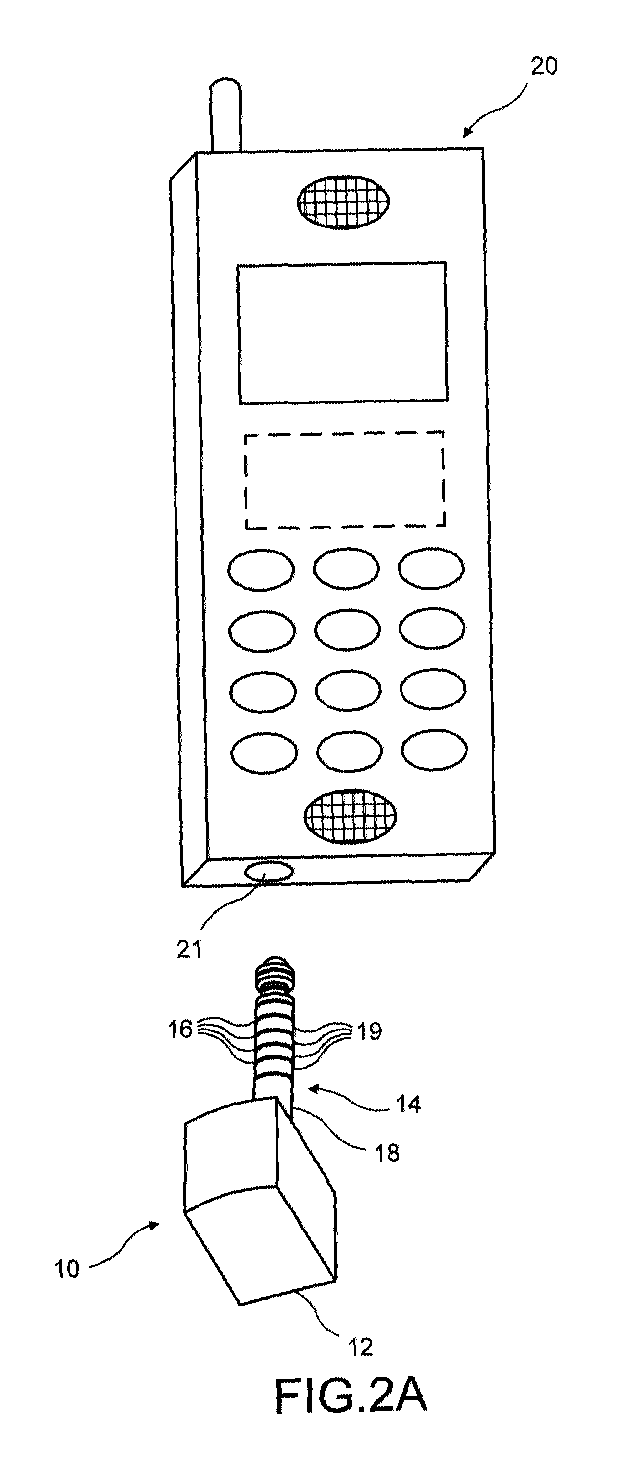
- FIG. 2a there is shown a camera module 10 and a radiotelephone 20 in accordance with an embodiment of the present invention.
- the camera module 10 is shown to be connectable to the radiotelephone 20 by means of a connector socket 21 which is provided in the bottom sidewall of the radio telephone. From a convenience of use perspective it may be preferable to provide the socket on a sidewall of the radiotelephone so that the camera module may be rotated about the horizontal axis with reference to the radiotelephone as shown in Figure 2b. This is a matter of design choice.
- the camera module 10 comprises a video camera unit 12 extending into an electrical connector plug 14.
- the camera unit 12 includes the necessary camera components and circuitry for a fully functioning video camera module.
- the plug 14 has at axially spaced apart locations along the length a series of transverse electrical contacts rings 16.
- the number of the contact rings are determined by the particular electrical connections required for the video camera module (these will be discussed in detail later).
- the plug 14 also has a series of bearing surfaces which are the areas in Figure 2 designated 18 and 19 which are designed to facilitate the rotation of the plug when the camera module is connected to the radiotelephone via the socket 21 of the radiotelephone.
- the bearing surfaces are designed so as to provide a good mechanical fit with the socket of the connector and are designed to be able to be reliable up to a given number of rotations of the shaft.
- the bearing surface is made from any suitable bearing material for example PTFE and could on a larger scale comprise a bushing or comprise roller needle bearings.
- the radio telephone 20 includes a connector socket 21 which as illustrated in Figure 3 comprises a female body 22 and five electrical connectors 23, 24, 25, 26, 27.
- the electrical connectors 23 to 27 are circumferentially disposed at axially spaced locations inside the perimeter of the connector body 22 and each having a wiper contact associated therewith.
- Such a connector socket of a radiotelephone is typically used to connect to the radiotelephone external electrical devices, such as a headset, to afford the radiotelephone additional functionality, in the case of a headset to allow a hands-free mode of operation of the radiotelephone.
- a connector may be used for receiving a plug of a charging unit for charging the battery of the radiotelephone.
- the camera module 10 is coupled with the radiotelephone 20 via the electrical contact rings 16 on the connector plug 14 mating with the electrical connectors 23, 24, 25, 26, 27 of female socket body 22.
- the arrangement of the present invention is such that the socket 21 can be used for connection of any number of different external electrical devices including the camera module, and in particular for interchanging use between a camera module and a headset.
- a function of the preferred form of the present invention being to detect which one of the camera module or headset is connected to the phone at any given time and then switching to electrically connect the radiotelephone to the camera module or headset according to which one is detected.
- the radiotelephone has discrete electrical areas on its electrical engine board dedicated to receive different input signals from a number of external electrical devices corresponding respectively to different modes of operation;
- the connector socket acts as an inlet port for allowing mechanical coupling of the different external electrical devices on an individually selectable basis; and an electrical interface determines which of the external electrical device has been plugged into the socket and effectively routes signals between the external electrical device and the corresponding electrical areas on the engine board.
- the present invention in a specific context is concerned with alternately connecting a camera module into a radiotelephone and a headset into the radiotelephone through a common connector and providing electrical interface circuitry comprising detection means for detecting from the plurality of modes of operation that the video camera module has been attached to the portable radio communication device and switching means for switching between the plurality of modes of operation to select the video camera mode of operation.
- the connector socket 21 of the radiotelephone has five electrical connectors 23 to 27. So as to electrically couple a camera module to the electrical engine board of the radiotelephone, the connector 21 receives 5 electrical signal inputs fed to it from the camera module and these are multiplexed through to 5 electrical contact points on the engine board of the radiotelephone.
- the electrical contact points on the engine board for the video camera input signals consist of:
- the camera module 10 may have more than 5 output signals.
- the camera module may comprise the following 10 signal outputs: Gnd, Gnd, DaClk, TxDa, RxDa, CSX, ExtClk, Vctrl, Vbat, VDDI.
- the number of signals input to the radiotelephone are combined in the camera in accordance with the following:
- VDDI is a supply (1.8V) to the I/O logic on the camera module.
- Vctrl is a control signal to turn on the on-board regulator.
- Vctrl logic voltage is 1.8V and hence the signals can be joined together. The regulator can turn on when the I/O power is supplied to the module.
- Vbat is used to supply the power to the on-board regulator.
- Vcam regulated 2.78V, 50mA
- the module can use this to power the on-board components and regulate to desired levels for the CCD.
- the same supply can be used to generate the I/O voltage by an on-board 1.8V regulator.
- the regulator output connects to VDDI and Vctrl as explained above.
- the camera module takes approximately 35mA from Vbat.
- This clock is used on the camera module by the DSP on the camera module to process data, and it can be derived from system clock rate of the engine. It does not have to be related to the system clock, it is the only high-speed clock available from the engine.
- DaClk Internally generate data clock DaClk from ExtClk. DaClk can be ExtClk divided by 2. This requires a flip flop on the camera module end.
- the ASIC which generates the ExtCIK part of the engine already will support a half Clk signal ( ⁇ 2).
- Figure 4 outlines these combinations and also the relationship of the combined signals with the contact points of the engine board.
- the 5 signals are output to the phone through the electrical contact rings 16 of connector plug 14 of the camera module.
- Figures 5a to 5d show schemes for multiplexing the camera and the headset signals.
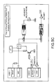
- Figure 5e schematically shows in overview the basic interfacing scheme
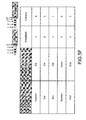
- Figure 5f give details of the connecting correlations between the headset connector and the camera connector.
- FIG. 5a depicts use of Shared Camera Data and Accessory Identification Line.
- the headset interrupt signal (HEADINT line) shares with the camera data line.
- HEADINT line shares with the camera data line.
- the HEADINT line is pulled to ground as the socket contact is connected to the grounded sleeve of the four-way headset plug.
- the socket contact connects to the extra jack ring contact.
- the pull-down resistor in the unpowered camera will result in about 0.5V on HEADINT which can be detected by the ADC connected to HEADINT inside ASIC 1.
- HEADINT falling to less than approximately 1.2V causes an interrupt then the system can read the ADC.
- HEADINT rising also causes an interrupt and can be used to detect headset removal. While the camera is in operation the interrupts must be disabled, or the camera data will create continuous interrupts.
- the camera is polled by software to ensure that it is still connected and the disconnection of the camera is detected by a lack of response from the camera.
- the radiotelephone On power up, and in unspecified cases, the radiotelephone is configured to default to headset mode.
- the headset detection ADC is read once the power supplies have stabilised. This will allow the appropriate mode to be selected for the camera enable (CAM_EN) select line. This drives the multiplexing switches to the correct state.
- Figure 5b shows use of shared camera clock and headset earpiece.
- the headset earpiece is typically a 32 ⁇ device.
- the analogue switch used for the microphone line has an impedance which varies from about 5 ⁇ to 40 ⁇ depending on where between the supply rails the signal voltage happens to be, i.e. the impedance is non-linear and causes distortion. So with a 32 ⁇ load a switch cannot be used.
- This described embodiment is also designed to support internal hands-free (IHF) functionality in which the phone has a built-in microphone capable of receiving and distinguishing audio signals (eg user speech) when the user is not holding the phone to his/her mouth, but has it placed on for example a table top.
- IHF internal hands-free
- ASIC 1 When in camera mode, ASIC 1 is set such that the HF and HFCM (hands-free common mode) drivers are enabled but only the HF output is driven with the audio signal.
- the d.c. level present on HFCM is prevented from upsetting the CAMCLK signal by the d.c. blocking capacitor.
- the fully active HF output allows the IHF to operate while the camera is being used.
- the CAMCLK driver is on and is driven with the camera clock signal. This clock signal is effectively isolated from the shorting effects of the HFCM driver by an inductor. This presents an impedance which the clock driver can drive easily.
- the capacitors to ground around the inductor form a low-pass filter to stop the clock signal from reaching the HFCM driver and possibly disrupting ASIC 1.
- the resistors are part of the usual headset circuit and are so arranged as to further attenuate the high frequency clock harmonics which may be above the effective blocking range of the inductor.
- both the HF and HFCM drivers are enabled as before, but now audio can be routed out of both.
- the IHF enable line determines whether the IHF is on at the same time as the headset. This is a requirement during ringing tones.
- the inductor presents about 1 ⁇ impedance, and the capacitors present more than 2.6k ⁇ impedance at 6kHz.
- Figure 5c shows use of shared camera chip select (CSX) and headset microphone line.
- CSX shared camera chip select
- headset mode the standard microphone input and bias resistor arrangement are connected through to the headset socket via an electronic FET switch.
- the high impedance of the ASIC 1 microphone input means that the mic signal is passed through the "on" impedance of the switch with no audible effect.
- the camera CSX line is tristated in headset mode and the tristate output does not add noticeably to the microphone noise level.
- the switch requires the enable to go all the way to the switch supply line and so has a transistor level shifter. This also provides the required logic negation.
- the switch to the microphone line is opened.
- the CSX logic driver is enabled and this drives the logic signal to the camera.
- the open switch provides a high impedance to the logic signal and avoids any damage to the ASIC 1 microphone inputs.
- Figure 5d shows use of shared headset switch and camera power line.
- the outer ring of the four-wire headset socket is found to be a good connection to attach the camera power to, as it can physically not be connected at random to the other signals upon insertion of the plug.
- the regulator is fully short circuit protected and will fold-back to less than 150mA when shorted.
- the power is only enabled when a camera has been identified.
- the output of the regulator is high impedance when disabled. This allows the line to be used to detect the closing of the headset switch when in headset mode.
- a headset on-hook/off-hook switch provided in the form of a button on the headset will go low when the button is pressed on the headset. There is a time constant associated with the button so fast double-clicks on this button will not be detected.
- the button can be used for various purposes e.g. call origination and call dropping. It is not usual for a HOOKINT signal to be seen in either in camera or 'nothing connected' mode. If this occurs then the 'nothing connected' state must be entered and the ADC measured to check what is really connected. The software must ignore the interrupts which will occur on HOOKINT when the VCAM regulator is turned on and off. The rating of the switch in the headsets is sufficient to take the regulator short-circuit current without difficulty.
- the same connector socket of the radiotelephone can be used for both camera and headset functionality's.
- the detecting means detects between insertion of the headset connector or the video camera module, and thus effectively detects the presence or absence of the camera module.
- the switching means responds to detection of the headset or the video camera module and accordingly switches between headset functionality and video camera module functionality.
- the present invention may be embodied in other specific forms without departing from its essential attributes.
- the plug and socket arrangement between the radiotelephone and the camera module may be reversed.
Landscapes
- Engineering & Computer Science (AREA)
- Signal Processing (AREA)
- Human Computer Interaction (AREA)
- Computer Networks & Wireless Communication (AREA)
- Multimedia (AREA)
- Telephone Set Structure (AREA)
- Studio Devices (AREA)
- Mobile Radio Communication Systems (AREA)
- Telephone Function (AREA)
Abstract
Description
Gnd, Gnd, DaClk, TxDa, RxDa, CSX, ExtClk, Vctrl, Vbat, VDDI.
Thus, through this series of multiplexed connections the same connector socket of the radiotelephone can be used for both camera and headset functionality's. The detecting means detects between insertion of the headset connector or the video camera module, and thus effectively detects the presence or absence of the camera module. And the switching means responds to detection of the headset or the video camera module and accordingly switches between headset functionality and video camera module functionality.
Claims (8)
- A portable radio communication device having a camera module associated therewith,the portable radio communication device having a connector for detachably connecting thereto the camera module or one or more other electrical devices,the camera module and the one or more other electrical devices being detachably connectable to the portable radio communication device individually in a selectable manner,the connector comprising cooperating circular cross sectioned plug and socket arrangement between the camera or the one or more other electrical devices and the portable radio communication device,thereby allowing the camera module to rotate in relation to the portable radio communication device between different view taking orientations,the portable radio communication device having electrical interface circuitry associated with the connector and enabling transfer of electrical signals between the camera module or the other electrical devices and the portable radio communication device in the said individual selectable manner, the electrical interface circuitry comprisingdetection means operative to detect the presence of the camera module from the other electrical devices,and switching means operable to switch between electrical coupling of the one or more other electrical devices and electrical coupling of the camera module in response to detection of the presence of the camera module so as to place the portable radio communication device in a condition to receive image signals from the camera module.
- A portable radio communication device having a video camera module associated therewith,the portable radio communication device having connection means for detachably connecting thereto the video camera module or one or more other electrical devices,the video camera module and the one or more other electrical devices being detachably connectable to the portable radio communication device individually in a selectable manner,the connection means comprising a mechanical coupling and electrical interface circuitry,the mechanical coupling being in the form of a plug and socket arrangement between the video camera module or the other electrical devices and the portable radio communication device, the arrangement allowing the video camera module to rotate relative to the portable radio communication device between different view taking orientations,the electrical interface circuitry supporting electrical connection of the video camera module or the other electrical devices to the portable radio communication device in the said individual selectable manner, the electrical interface circuitry comprisingdetection means operative to detect the presence of the camera module from the other electrical devices,and switching means operable to switch between electrical coupling of the one or more other electrical devices and electrical coupling of the video camera module in response to detection of the presence of the video camera module so as to place the portable radio communication device in a condition to receive video signals from the video camera module.
- A portable radio communication device according to claim 1 or claim 2, wherein the one or more other electrical devices comprises a headset and the detection means is operative to detect the presence of the camera module or the headset, and the switching means is operable to switch between electrical coupling of the headset and electrical coupling of the video camera module in response to detection of the headset or the video camera module.
- A portable radio communication device according to claim 1, claim 2 or claim 3, wherein the detection means and the switching means are provided in the form of multiplexing circuitry.
- A portable radio communication device according to claim 4, wherein said multiplexing circuitry comprises common electrical connection lines between selected electrical signal lines of the camera and selected electrical signal lines of the headset.
- A portable radio communication device according to claim 5, wherein said multiplexing circuitry comprises any one or combinations of the following electrical connections:a shared line between camera data and headset identification,a share line between camera clock and headset earpiece,a shared line between camera select and headset microphone,a shared line between a camera power and a headset switch.
- A camera module adapted to be detachably connected to a portable radio communication device as defined in any preceding claim.
- A portable radio communication device having a camera module and one or more other electrical devices associated therewith,the portable radio communication device having a connector for detachably connecting thereto the camera module and the one or more other electrical devices,the camera module and the one or more other electrical devices being detachably connectable to the portable radio communication device via the connector in an individually selectable manner,the portable radio communication device having electrical interface circuitry associated with the connector and enabling transfer of electrical signals between the camera module or the one or more other electrical devices andthe portable radio communication device in the said individual selectable manner,the electrical interface circuitry comprising switching means operable to switch between electrical coupling of the one or more other electrical devices andelectrical coupling of the camera module to the portable radio communication device in dependence upon which selected one of the one or more other electrical devices or the camera module is coupled to the portable radio communication device via the connector.
Applications Claiming Priority (2)
| Application Number | Priority Date | Filing Date | Title |
|---|---|---|---|
| GB0005888A GB2360161B (en) | 2000-03-10 | 2000-03-10 | Mobile imaging |
| GB0005888 | 2000-03-10 |
Publications (2)
| Publication Number | Publication Date |
|---|---|
| EP1133185A2 true EP1133185A2 (en) | 2001-09-12 |
| EP1133185A3 EP1133185A3 (en) | 2001-12-12 |
Family
ID=9887433
Family Applications (1)
| Application Number | Title | Priority Date | Filing Date |
|---|---|---|---|
| EP01301312A Withdrawn EP1133185A3 (en) | 2000-03-10 | 2001-02-15 | Mobile imaging |
Country Status (4)
| Country | Link |
|---|---|
| US (1) | US6518993B2 (en) |
| EP (1) | EP1133185A3 (en) |
| JP (1) | JP2001313697A (en) |
| GB (1) | GB2360161B (en) |
Cited By (17)
| Publication number | Priority date | Publication date | Assignee | Title |
|---|---|---|---|---|
| WO2001065827A3 (en) * | 2000-02-29 | 2002-06-13 | Kyocera Corp | Portable information terminal and digital camera therefor, and portable digital camera information terminal system |
| GB2380081A (en) * | 2001-09-12 | 2003-03-26 | Roderick Matthew Shears | Secure image mobile telephone. |
| FR2833092A1 (en) * | 2001-11-30 | 2003-06-06 | Yves Reza | SELECTION AND POSITION DETECTOR AND VIRTUAL KEYBOARD USING LIGHT SOURCES |
| WO2003077506A1 (en) * | 2002-03-14 | 2003-09-18 | Nokia Corporation | Accessory part for a mobile station |
| KR100480073B1 (en) * | 2002-11-20 | 2005-03-31 | 엘지전자 주식회사 | External apparatus for interface circuit of mobile phone |
| EP1487196A4 (en) * | 2002-03-19 | 2005-06-01 | Mitsubishi Electric Corp | CAMERA MOBILE PHONE DEVICE AND CAMERA LIGHTING DEVICE |
| EP1600886A1 (en) * | 2004-05-18 | 2005-11-30 | Aiptek International Inc. | Information processing device with expansible function module |
| WO2006045617A3 (en) * | 2004-10-25 | 2006-06-15 | Nokia Corp | Detection, identification and operation of pherpherals connected via an audio/video-plug to an electronic device |
| EP1898631A1 (en) * | 2006-09-07 | 2008-03-12 | Pace Micro Technology PLC | Mobile communication device and base or holder therefor |
| EP1978439A1 (en) * | 2007-04-05 | 2008-10-08 | Giga-Byte Communications, Inc. | Trigger operated portable electronic device |
| EP1518180A4 (en) * | 2002-06-24 | 2009-06-17 | Analog Devices Inc | Identification system and method for recognizing any one of a number of different types of devices |
| EP1879377A3 (en) * | 2006-07-13 | 2010-06-16 | Panasonic Corporation | Portable Device |
| US7783058B2 (en) | 2002-06-24 | 2010-08-24 | Analog Devices, Inc. | System for verifying the identification of a device |
| US7912668B2 (en) | 2002-06-24 | 2011-03-22 | Analog Devices, Inc. | System for determining the true electrical characteristics of a device |
| US8180397B2 (en) | 2009-10-28 | 2012-05-15 | Research In Motion Limited | Mobile communications device accessory identification system, an improved accessory for use with a mobile communications device, and a method of identifying same |
| TWI452302B (en) * | 2012-11-30 | 2014-09-11 | Hon Hai Prec Ind Co Ltd | Portable device for current measuring and current measuring method |
| WO2021164715A1 (en) * | 2020-02-21 | 2021-08-26 | 维沃移动通信有限公司 | Electronic device |
Families Citing this family (37)
| Publication number | Priority date | Publication date | Assignee | Title |
|---|---|---|---|---|
| US7224962B1 (en) | 1997-10-03 | 2007-05-29 | Karen Jeanne Kite | Remote operational screener |
| JP2001292085A (en) * | 2000-04-10 | 2001-10-19 | Mitsubishi Electric Corp | Non-contact transmission device |
| US7224851B2 (en) * | 2001-12-04 | 2007-05-29 | Fujifilm Corporation | Method and apparatus for registering modification pattern of transmission image and method and apparatus for reproducing the same |
| KR100455139B1 (en) * | 2001-12-29 | 2004-11-06 | 엘지전자 주식회사 | Side receptacle type camera phone |
| JP2003219062A (en) * | 2002-01-21 | 2003-07-31 | Nec Corp | Mobile phone with crime-preventing function and crime- prevention adaptor for the mobile phone |
| JP3882687B2 (en) * | 2002-06-11 | 2007-02-21 | 日本電気株式会社 | Portable communication device |
| JP2004048682A (en) * | 2002-07-09 | 2004-02-12 | Samsung Electro Mech Co Ltd | Mobile telephone |
| KR100474295B1 (en) * | 2002-07-30 | 2005-03-10 | 엘지전자 주식회사 | Mobile handset having camera apparatus |
| US7027836B2 (en) * | 2002-09-10 | 2006-04-11 | Eastman Kodak Company | Method and system for establishing a communication network |
| KR100602719B1 (en) * | 2002-09-26 | 2006-07-20 | 주식회사 팬택앤큐리텔 | Ear Jack Auto Detect Circuit and Method |
| JP2004304560A (en) | 2003-03-31 | 2004-10-28 | Fujitsu Ltd | Electronic equipment |
| TW568481U (en) * | 2003-05-16 | 2003-12-21 | Hon Hai Prec Ind Co Ltd | Digital camera |
| KR20040100332A (en) * | 2003-05-22 | 2004-12-02 | 엘지전자 주식회사 | Earphone apparatus for mobile phone |
| JP2004350206A (en) * | 2003-05-26 | 2004-12-09 | Sharp Corp | Imaging equipment |
| US20050014527A1 (en) * | 2003-07-18 | 2005-01-20 | Agere Systems Incorporated | Retractable rotatable camera module for mobile communication device and method of operation thereof |
| US8209441B1 (en) * | 2003-12-12 | 2012-06-26 | Plantronics, Inc. | On-line status detection for host-based headset applications |
| KR100619898B1 (en) * | 2004-08-24 | 2006-09-19 | 엘지전자 주식회사 | Mobile communication terminal having an external device detection function and method thereof |
| US7283044B2 (en) * | 2005-03-29 | 2007-10-16 | Symbol Technologies, Inc. | Method and apparatus for a privacy enabling radio frequency identification (RFID) reader |
| KR100730722B1 (en) * | 2005-07-29 | 2007-06-21 | 삼성전자주식회사 | DM package for receiving digital multimedia broadcasting data, mobile terminal and digital multimedia broadcasting data receiving method |
| JP2009504098A (en) * | 2005-08-01 | 2009-01-29 | ザ ビデオ ワークス, インコーポレイテッド | 2-part camera system |
| KR100630123B1 (en) * | 2005-08-31 | 2006-09-28 | 삼성전자주식회사 | Mobile terminal accessory device and method for receiving and playing digital multimedia broadcasting data |
| TW200726196A (en) * | 2005-12-27 | 2007-07-01 | Altek Corp | Mobile communication device with camera and practice thereof |
| US20080182442A1 (en) * | 2007-01-31 | 2008-07-31 | Jaeho Choi | Data Port for a Mobile Device |
| TWI502949B (en) * | 2008-04-11 | 2015-10-01 | Asustek Comp Inc | Portable electric device with rotatable image-capturing module |
| US10354407B2 (en) * | 2013-03-15 | 2019-07-16 | Spatial Cam Llc | Camera for locating hidden objects |
| US9513616B2 (en) * | 2010-10-15 | 2016-12-06 | Blackberry Limited | System and method for controlling functions on electronic devices |
| US8750537B2 (en) * | 2010-12-06 | 2014-06-10 | Blackberry Limited | Differential microphone circuit |
| US8812140B2 (en) * | 2011-05-16 | 2014-08-19 | Jogtek Corp. | Signal transforming method, transforming device through audio interface and application program for executing the same |
| JP5975360B2 (en) * | 2011-10-20 | 2016-08-23 | ▲華▼▲為▼▲終▼端有限公司 | General purpose connectors and handheld electronic devices |
| DE202013101240U1 (en) * | 2013-03-22 | 2014-06-23 | Peter Lutz | Mobile telephone with video telephony function, external optical recording device therefor and a video telephony system |
| US20150295973A1 (en) * | 2014-04-10 | 2015-10-15 | Screenovate Technologies Ltd. | Method for real-time multimedia interface management |
| US9736567B2 (en) | 2014-09-29 | 2017-08-15 | Qualcomm Incorporated | Electronics interface for device headset jack |
| US9309012B1 (en) | 2015-06-13 | 2016-04-12 | Google Inc. | Method of packaging camera facilitating ease of installation |
| US9388934B1 (en) | 2015-06-13 | 2016-07-12 | Google Inc. | Camera stand having constant resistance for a portion of a range of motion along an axis of rotation |
| US9377157B1 (en) * | 2015-06-13 | 2016-06-28 | Google Inc. | Camera stand having an unlimited range of motion along an axis of rotation |
| US10237461B2 (en) | 2017-03-01 | 2019-03-19 | Intel Corporation | Dual form factor devices having operative and complementary aligning components |
| US20190014199A1 (en) * | 2017-07-10 | 2019-01-10 | Canon Kabushiki Kaisha | Electronic equipment and method for controlling the same |
Family Cites Families (9)
| Publication number | Priority date | Publication date | Assignee | Title |
|---|---|---|---|---|
| US5550754A (en) * | 1994-05-13 | 1996-08-27 | Videoptic Research | Teleconferencing camcorder |
| FI115739B (en) * | 1994-05-19 | 2005-06-30 | Nokia Corp | Device for personal communication, data collection and processing and circuit boards |
| JP2590754B2 (en) | 1994-09-28 | 1997-03-12 | 日本電気株式会社 | Calling method and apparatus for mobile communication system |
| US6654050B2 (en) * | 1994-09-28 | 2003-11-25 | Canon Kabushiki Kaisha | Image input unit |
| GB9600804D0 (en) * | 1996-01-17 | 1996-03-20 | Robb Garry D | Multiphone |
| EP0830000A2 (en) * | 1996-09-11 | 1998-03-18 | Hewlett-Packard Company | Apparatus and method for connecting portable phone to portable image capture device |
| DE19638882A1 (en) * | 1996-09-21 | 1998-04-02 | Kai Rosenboom | Telephone and CCD camera unit |
| US6677936B2 (en) * | 1996-10-31 | 2004-01-13 | Kopin Corporation | Color display system for a camera |
| EP0975132A1 (en) * | 1998-07-20 | 2000-01-26 | Alcatel | Telecommunication system comprising at least a mobile phone and at least a camera unit |
-
2000
- 2000-03-10 GB GB0005888A patent/GB2360161B/en not_active Expired - Fee Related
-
2001
- 2001-02-15 EP EP01301312A patent/EP1133185A3/en not_active Withdrawn
- 2001-03-09 JP JP2001066069A patent/JP2001313697A/en not_active Withdrawn
- 2001-03-12 US US09/803,151 patent/US6518993B2/en not_active Expired - Fee Related
Cited By (22)
| Publication number | Priority date | Publication date | Assignee | Title |
|---|---|---|---|---|
| WO2001065827A3 (en) * | 2000-02-29 | 2002-06-13 | Kyocera Corp | Portable information terminal and digital camera therefor, and portable digital camera information terminal system |
| GB2380081A (en) * | 2001-09-12 | 2003-03-26 | Roderick Matthew Shears | Secure image mobile telephone. |
| FR2833092A1 (en) * | 2001-11-30 | 2003-06-06 | Yves Reza | SELECTION AND POSITION DETECTOR AND VIRTUAL KEYBOARD USING LIGHT SOURCES |
| WO2003046820A3 (en) * | 2001-11-30 | 2004-01-22 | Yves Reza | Position sensing and virtual keyboard with light sources |
| US7512416B2 (en) | 2002-03-14 | 2009-03-31 | Kati Arell | Accessory part for a mobile station |
| WO2003077506A1 (en) * | 2002-03-14 | 2003-09-18 | Nokia Corporation | Accessory part for a mobile station |
| EP1487196A4 (en) * | 2002-03-19 | 2005-06-01 | Mitsubishi Electric Corp | CAMERA MOBILE PHONE DEVICE AND CAMERA LIGHTING DEVICE |
| US7912668B2 (en) | 2002-06-24 | 2011-03-22 | Analog Devices, Inc. | System for determining the true electrical characteristics of a device |
| US7890284B2 (en) | 2002-06-24 | 2011-02-15 | Analog Devices, Inc. | Identification system and method for recognizing any one of a number of different types of devices |
| US7783058B2 (en) | 2002-06-24 | 2010-08-24 | Analog Devices, Inc. | System for verifying the identification of a device |
| EP1518180A4 (en) * | 2002-06-24 | 2009-06-17 | Analog Devices Inc | Identification system and method for recognizing any one of a number of different types of devices |
| KR100480073B1 (en) * | 2002-11-20 | 2005-03-31 | 엘지전자 주식회사 | External apparatus for interface circuit of mobile phone |
| EP1600886A1 (en) * | 2004-05-18 | 2005-11-30 | Aiptek International Inc. | Information processing device with expansible function module |
| WO2006045617A3 (en) * | 2004-10-25 | 2006-06-15 | Nokia Corp | Detection, identification and operation of pherpherals connected via an audio/video-plug to an electronic device |
| US8412268B2 (en) | 2004-10-25 | 2013-04-02 | Nokia Corporation | Detection, identification and operation of pheripherals connected via an audio/video-plug to an electronic device |
| CN101951446B (en) * | 2004-10-25 | 2016-11-23 | 诺基亚技术有限公司 | It is connected to the detection of the ancillary equipment of electronic equipment via audio/video plug, identifies and operate |
| EP1879377A3 (en) * | 2006-07-13 | 2010-06-16 | Panasonic Corporation | Portable Device |
| EP1898631A1 (en) * | 2006-09-07 | 2008-03-12 | Pace Micro Technology PLC | Mobile communication device and base or holder therefor |
| EP1978439A1 (en) * | 2007-04-05 | 2008-10-08 | Giga-Byte Communications, Inc. | Trigger operated portable electronic device |
| US8180397B2 (en) | 2009-10-28 | 2012-05-15 | Research In Motion Limited | Mobile communications device accessory identification system, an improved accessory for use with a mobile communications device, and a method of identifying same |
| TWI452302B (en) * | 2012-11-30 | 2014-09-11 | Hon Hai Prec Ind Co Ltd | Portable device for current measuring and current measuring method |
| WO2021164715A1 (en) * | 2020-02-21 | 2021-08-26 | 维沃移动通信有限公司 | Electronic device |
Also Published As
| Publication number | Publication date |
|---|---|
| US6518993B2 (en) | 2003-02-11 |
| JP2001313697A (en) | 2001-11-09 |
| EP1133185A3 (en) | 2001-12-12 |
| GB2360161B (en) | 2004-06-16 |
| GB0005888D0 (en) | 2000-05-03 |
| GB2360161A (en) | 2001-09-12 |
| US20010020975A1 (en) | 2001-09-13 |
Similar Documents
| Publication | Publication Date | Title |
|---|---|---|
| US6518993B2 (en) | Mobile imaging | |
| US6452402B1 (en) | Apparatus for determining the type of external device being connected | |
| EP1573866B1 (en) | Combination audio/charger jack | |
| AU703649B2 (en) | Conformant compact portable cellular phone case system and connector | |
| US6615059B1 (en) | Mobile terminal interface | |
| US20040063464A1 (en) | High-speed data and power source interface cable for mobile devices | |
| CN101184383A (en) | Portable electronic device including hinge assembly with user interface element | |
| US7085596B2 (en) | Portable communication apparatus | |
| JP5057119B2 (en) | Holding stand and information processing system | |
| JP2003530023A (en) | Support for mobile terminals | |
| JPH1098561A (en) | Communication equipment | |
| WO2009063278A1 (en) | Multipurpose universal bus cable | |
| JP2571162B2 (en) | Mobile phone equipment | |
| US7351065B1 (en) | Method and electronic device connector with band and angle encoding | |
| US6081594A (en) | Hands-free device with a replaceable adapter for a mobile phone | |
| US20050219843A1 (en) | Accessory part for a mobile station | |
| US8229514B2 (en) | DECT wireless hands-free communication apparatus | |
| JPH08237345A (en) | Charging table and charging and data transmission system for radio telephone equipment | |
| CN105744075A (en) | Interconnection Method of Mobile Phone Based on OTG Technology | |
| GB2354377A (en) | Electrical jack plug acting as a pivot | |
| US20050221859A1 (en) | Electronic system and device utilizing the same | |
| KR100469418B1 (en) | Mobile communication terminal having necklace with camera attached | |
| KR200400196Y1 (en) | Earphone apparatus with memory expansion module using USB port for data linking | |
| JPH03204260A (en) | Cordless phone system | |
| KR100698321B1 (en) | Mobile communication terminal |
Legal Events
| Date | Code | Title | Description |
|---|---|---|---|
| PUAI | Public reference made under article 153(3) epc to a published international application that has entered the european phase |
Free format text: ORIGINAL CODE: 0009012 |
|
| AK | Designated contracting states |
Kind code of ref document: A2 Designated state(s): AT BE CH CY DE DK ES FI FR GB GR IE IT LI LU MC NL PT SE TR |
|
| AX | Request for extension of the european patent |
Free format text: AL;LT;LV;MK;RO;SI |
|
| PUAL | Search report despatched |
Free format text: ORIGINAL CODE: 0009013 |
|
| AK | Designated contracting states |
Kind code of ref document: A3 Designated state(s): AT BE CH CY DE DK ES FI FR GB GR IE IT LI LU MC NL PT SE TR |
|
| AX | Request for extension of the european patent |
Free format text: AL;LT;LV;MK;RO;SI |
|
| RAP1 | Party data changed (applicant data changed or rights of an application transferred) |
Owner name: NOKIA CORPORATION |
|
| 17P | Request for examination filed |
Effective date: 20020612 |
|
| AKX | Designation fees paid |
Free format text: AT BE CH CY DE DK ES FI FR GB GR IE IT LI LU MC NL PT SE TR |
|
| STAA | Information on the status of an ep patent application or granted ep patent |
Free format text: STATUS: THE APPLICATION HAS BEEN WITHDRAWN |
|
| 18W | Application withdrawn |
Effective date: 20021211 |