EP1133176A2 - Magnetic recording and reproducing apparatus - Google Patents
Magnetic recording and reproducing apparatus Download PDFInfo
- Publication number
- EP1133176A2 EP1133176A2 EP01301586A EP01301586A EP1133176A2 EP 1133176 A2 EP1133176 A2 EP 1133176A2 EP 01301586 A EP01301586 A EP 01301586A EP 01301586 A EP01301586 A EP 01301586A EP 1133176 A2 EP1133176 A2 EP 1133176A2
- Authority
- EP
- European Patent Office
- Prior art keywords
- osd
- aspect ratio
- video
- signal
- display
- Prior art date
- Legal status (The legal status is an assumption and is not a legal conclusion. Google has not performed a legal analysis and makes no representation as to the accuracy of the status listed.)
- Withdrawn
Links
Images


Classifications
-
- H—ELECTRICITY
- H04—ELECTRIC COMMUNICATION TECHNIQUE
- H04N—PICTORIAL COMMUNICATION, e.g. TELEVISION
- H04N5/00—Details of television systems
- H04N5/76—Television signal recording
- H04N5/78—Television signal recording using magnetic recording
- H04N5/782—Television signal recording using magnetic recording on tape
-
- H—ELECTRICITY
- H04—ELECTRIC COMMUNICATION TECHNIQUE
- H04N—PICTORIAL COMMUNICATION, e.g. TELEVISION
- H04N7/00—Television systems
- H04N7/01—Conversion of standards, e.g. involving analogue television standards or digital television standards processed at pixel level
- H04N7/0117—Conversion of standards, e.g. involving analogue television standards or digital television standards processed at pixel level involving conversion of the spatial resolution of the incoming video signal
- H04N7/0122—Conversion of standards, e.g. involving analogue television standards or digital television standards processed at pixel level involving conversion of the spatial resolution of the incoming video signal the input and the output signals having different aspect ratios
-
- H—ELECTRICITY
- H04—ELECTRIC COMMUNICATION TECHNIQUE
- H04N—PICTORIAL COMMUNICATION, e.g. TELEVISION
- H04N21/00—Selective content distribution, e.g. interactive television or video on demand [VOD]
- H04N21/40—Client devices specifically adapted for the reception of or interaction with content, e.g. set-top-box [STB]; Operations thereof
- H04N21/43—Processing of content or additional data, e.g. demultiplexing additional data from a digital video stream; Elementary client operations, e.g. monitoring of home network or synchronising decoder's clock; Client middleware
- H04N21/431—Generation of visual interfaces for content selection or interaction; Content or additional data rendering
- H04N21/4312—Generation of visual interfaces for content selection or interaction; Content or additional data rendering involving specific graphical features, e.g. screen layout, special fonts or colors, blinking icons, highlights or animations
-
- H—ELECTRICITY
- H04—ELECTRIC COMMUNICATION TECHNIQUE
- H04N—PICTORIAL COMMUNICATION, e.g. TELEVISION
- H04N21/00—Selective content distribution, e.g. interactive television or video on demand [VOD]
- H04N21/40—Client devices specifically adapted for the reception of or interaction with content, e.g. set-top-box [STB]; Operations thereof
- H04N21/43—Processing of content or additional data, e.g. demultiplexing additional data from a digital video stream; Elementary client operations, e.g. monitoring of home network or synchronising decoder's clock; Client middleware
- H04N21/432—Content retrieval operation from a local storage medium, e.g. hard-disk
- H04N21/4325—Content retrieval operation from a local storage medium, e.g. hard-disk by playing back content from the storage medium
-
- H—ELECTRICITY
- H04—ELECTRIC COMMUNICATION TECHNIQUE
- H04N—PICTORIAL COMMUNICATION, e.g. TELEVISION
- H04N21/00—Selective content distribution, e.g. interactive television or video on demand [VOD]
- H04N21/40—Client devices specifically adapted for the reception of or interaction with content, e.g. set-top-box [STB]; Operations thereof
- H04N21/43—Processing of content or additional data, e.g. demultiplexing additional data from a digital video stream; Elementary client operations, e.g. monitoring of home network or synchronising decoder's clock; Client middleware
- H04N21/44—Processing of video elementary streams, e.g. splicing a video clip retrieved from local storage with an incoming video stream or rendering scenes according to encoded video stream scene graphs
- H04N21/4402—Processing of video elementary streams, e.g. splicing a video clip retrieved from local storage with an incoming video stream or rendering scenes according to encoded video stream scene graphs involving reformatting operations of video signals for household redistribution, storage or real-time display
- H04N21/440263—Processing of video elementary streams, e.g. splicing a video clip retrieved from local storage with an incoming video stream or rendering scenes according to encoded video stream scene graphs involving reformatting operations of video signals for household redistribution, storage or real-time display by altering the spatial resolution, e.g. for displaying on a connected PDA
- H04N21/440272—Processing of video elementary streams, e.g. splicing a video clip retrieved from local storage with an incoming video stream or rendering scenes according to encoded video stream scene graphs involving reformatting operations of video signals for household redistribution, storage or real-time display by altering the spatial resolution, e.g. for displaying on a connected PDA for performing aspect ratio conversion
-
- H—ELECTRICITY
- H04—ELECTRIC COMMUNICATION TECHNIQUE
- H04N—PICTORIAL COMMUNICATION, e.g. TELEVISION
- H04N5/00—Details of television systems
- H04N5/44—Receiver circuitry for the reception of television signals according to analogue transmission standards
- H04N5/445—Receiver circuitry for the reception of television signals according to analogue transmission standards for displaying additional information
Definitions
- the present invention relates to a magnetic recording and reproducing apparatus which can change a display location of on-screen-display (OSD) on a display device responsive to an aspect ratio of a video.
- OSD on-screen-display
- the aspect ratio is a ratio of horizontal length vs. vertical length of a display area displayed on a screen of the display device.
- a content recorded by HD method in the format of 16:9 aspect ratio may be broadcasted in the 4:3 aspect ratio format, or often used as a recorded video source.
- This wide-display-device has various displaying functions as follows:
- a magnetic recording and reproducing apparatus such as a video tape recorder (VTR)
- VTR video tape recorder
- OSD on-screen-display
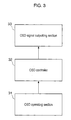
- Fig. 3 is a block diagram showing a structure of an OSD of the conventional apparatus.
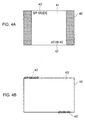
- Fig. 4 illustrates OSD displayed by the conventional magnetic recording and reproducing apparatus.
- OSD operating section 31 when OSD operating section 31 is operated, an OSD signal is output on a display device such as a television receiver (TV), and the OSD is displayed on the screen of the display device. Various modes and conditions of the magnetic recording and reproducing apparatus are displayed by using this OSD.
- OSD operating section 31 is provided in a body of a VTR or a remote controlling unit.
- OSD controller 32 generates OSD data, such as a binary video signal, for displaying an OSD through the operation of OSD operating section 31.
- OSD signal outputting section 33 inserts the data signal generated by OSD controller 32 into an output video signal.
- OSD data is displayed on the screen of the display device such as a TV.
- OSD controller 32 transmits his/her operating command to OSD controller 32 by operating OSD operating section 31, disposed to, e.g., a remote controlling unit, in order to confirm the status of the VTR or other conditions.
- OSD controller 32 generates OSD data responsive to the operation on section 31, and outputs the data to OSD signal outputting section 33.
- OSD signal outputting section 33 allows the OSD data to be included in an output signal from the VTR. This signal is supplied to the display device such as a TV.
- the OSD data is finally displayed on the screen of the display device.
- Fig. 4 shows a wide display, i.e., screen 40 having an aspect ration of 16:9, on which OSD data 42 of the conventional VTR discussed above is displayed.
- Fig. 4A illustrates a status where a video source is displayed on video display area 41 having a 4:3 aspect ratio.
- Fig. 4B illustrates a status where the same video source is displayed on entire video display area 43 having a 16:9 aspect ratio, i.e. a wide display.
- OSD data 42 is displayed.
- the OSD data indicates information of various conditions of the VTR and time information.
- Fig. 4B shows that OSD data 42 goes over screen 40, and stick-out portion of the data over screen 40, which should not appear on screen 40, is displayed for the explanation purpose.
- OSD data 42 displayed on a TV screen by OSD signal outputting section 33 is fixed at its location.
- the wide display shows a video of 4:3 aspect ratio as shown in Fig. 4A
- the OSD is displayed, and then the display is switched to 16:9 aspect ratio format as shown in Fig. 4B (function 3 of the wide display). This condition is considered hereinafter.
- the video may be expanded in a vertical direction when the video is converted into 16:9 format.
- OSD display data 42 is shifted in the vertical direction at the same time. Therefore, parts of or whole of OSD display data 42 may go over the screen and is not displayed.
- OSD when a video of 4:3 aspect ratio is displayed, OSD is practiced, then the function 1 of the wide display is carried out. At this time, parts of or whole of OSD display data 42 may not be displayed on the screen.
- the wide display have functions to display a video of different aspect ratios in a various formats, it is difficult to specify a displaying location of OSD data generated by a video signal source of a magnetic recording and reproducing apparatus.
- the present invention addresses the problem discussed above and aims to provide a magnetic recording and reproducing apparatus which can set a location of displaying an OSD responsive to a ratio of horizontal length vs. vertical length of the TV screen and an aspect ratio of a video image.
- the magnetic recording and reproducing apparatus of the present invention outputs a video output signal including an OSD signal
- the apparatus comprises the following elements:
- the OSD controller places the OSD signal at a location of the video output signal responsive to the selected aspect ratio.
- This structure allows the location of the OSD to be switched responsive to the aspect ratio of a display device including a TV and the aspect ratio of a video. Therefore, the OSD does not go over the screen of the display device, but is normally displayed.
- Fig. 1 is a block diagram showing a structure of a magnetic recording and reproducing apparatus in accordance with the exemplary embodiment of the present invention.
- Fig. 2 shows schematically a display status in accordance with the same exemplary embodiment.
- Fig. 2A shows that a video source in a 4:3 aspect ratio displayed on a wide display.
- Fig. 2B shows that the video source in a 16:9 aspect ration displayed on the wide display.
- OSD operating section 11 is disposed in a VTR or a remote controlling unit for a user to confirm a status of the VTR as well as generate OSD data in the VTR.
- OSD selector 14 has a function of selecting an aspect ratio for switching a display of the OSD responsive to an aspect ratio of a display area of a video source displayed on a display device such as a TV. For instance one of the aspect ratios of 16:9 and 4:3 is selected. Further, selector 14 outputs a signal, indicating a display location of the OSD responsive to the selected aspect ratio, to OSD controller 12.
- the OSD data is displayed in a display area of the video signal.
- the user can look at the OSD data without any drop-outs.
- OSD controller 12 When “Display OSD.” is input through OSD operating section 11, OSD controller 12 generates OSD data comprising binary video. This OSD data is not necessarily a binary, but may be a multi-level gradation data.
- Selector 14 determines whether the aspect ratio of an OSD picture selected is 4:3 or 16:9.
- OSD signal output section 13 inserts the OSD data generated by controller 12 into the video output signal, which is output to the display device such as a TV.
- the OSD data is thus displayed on the display device.
- the OSD data displayed indicates, e.g., a condition or various signs of the VTR.
- the display device can display a plurality of videos having different aspect ratios.
- selector 14 can select the aspect ratios of 16:9 and 4:3; however, if the display device can deal with other aspect ratios, the selector can be adjusted accordingly.
- screen 20 of the display device can display a video of 16:9 aspect ratio.
- Video display area 21 shows the area when the video of 4:3 aspect ratio is displayed.
- Video display area 23 shows the area when the video of 16:9 aspect ratio is displayed.
- OSD data 22 is displayed on screen 20 to indicate a condition and a counter number of the VTR.
- Line number 24 is a reference of a display location of OSD data 22. In this embodiment, a 12th line is a bottom line; however, the line number may take any number.
- a user operates OSD operating section 11 disposed in a remote controlling unit or the like in order to confirm a condition of the VTR.
- Operating section 11 transmits a command the user input to OSD controller 12, which generates OSD data responsive to the command.
- the OSD data then supplied to OSD signal output section 13, which inserts an OSD signal into a video output signal.
- the video output signal including the OSD signal is supplied to a display device such as a TV.
- the OSD data is thus displayed on a screen of the display device.
- the display device displays a video supplied from the VTR, such as a video recorded in the tape, or an on-air video of television broadcasting through a tuner built in the VTR, the OSD can be super-imposed on this video.
- the OSD may be displayed on a given background such as blue-back without displaying any video.
- controller 12 changes a location of the OSD data in the video output signal so that the OSD data can be placed within a screen of 16:9 aspect ratio.
- the OSD data displayed at an upper end and a lower end of the screen are located on the first line and the 12th line respectively.
- the display device changes a video aspect ratio to 16:9 as shown in Fig. 2B, then the video displayed in display area 21 is vertically expanded and the OSD is also moved in a vertical direction.
- OSD data 22 located on the first line and the 12th line go over the screen 20.
- Selector 14 shown in Fig. 1 is activated, so that OSD controller 12 moves the location of the OSD data in the video output signal.
- OSD data 22a originally located on the first line is moved to the third line as data 22b
- data 22a originally located on the 12th line is moved to the 10th line as data 22b. Therefore, whole data 22b can be normally displayed in screen 20.
- selector 14 selects the aspect ratio of 4:3.
- OSD controller 12 then moves the OSD data from the third and tenth lines to the first and 12th lines responsive to the selection by selector 14. The OSD data is thus displayed normally within the display area.
- a landscape video such as the video of 16:9 aspect ratio is detected, i.e., the fact is detected that the horizontal length of the landscape video is rather longer comparing with the video of normal aspect ratio. Then the operation discussed above is carried out, thereby moving the OSD data into the video display area. This performance corresponds to the items (b) and (c) discussed previously.
- the present invention proves that a display location of an OSD can be switched responsive to an aspect ratio of a screen of a display device such as a TV or an aspect ratio of a video source. Therefore, the OSD can be normally displayed without going over the TV screen.
Landscapes
- Engineering & Computer Science (AREA)
- Multimedia (AREA)
- Signal Processing (AREA)
- Computer Graphics (AREA)
- Television Signal Processing For Recording (AREA)
- Controls And Circuits For Display Device (AREA)
- Transforming Electric Information Into Light Information (AREA)
- Television Systems (AREA)
Abstract
Description
Claims (8)
- A magnetic recording and reproducing apparatus for outputting a video output signal including an on screen display (OSD) signal, said apparatus comprising:wherein when said selector selects a given aspect ratio, the OSD signal is placed at a location in the video output signal responsive to the given aspect ratio.(a) an OSD controller for generating the OSD signal;(b) an OSD signal outputting section which allows the OSD signal to be included in the video output signal; and(c) a selector for selecting an aspect ratio of a display area of the video output signal,
- The magnetic recording and reproducing apparatus as defined in Claim 1, wherein the location is within the display area of the video output signal.
- The magnetic recording and reproducing apparatus as defined in Claim 1 further comprising:an OSD operating section,wherein said selector selects the given aspect ratio responsive to an input signal from said OSD operating section.
- The magnetic recording and reproducing apparatus as defined in Claim 3, wherein a user operates said OSD operating section to select the given aspect ratio responsive to an aspect ratio of the display area of the video output signal.
- The magnetic recording and reproducing apparatus as defined in Claim 1, wherein said selector selects the given aspect ratio responsive to the video display area of the video output signal.
- The magnetic recording and reproducing apparatus as defined in Claim 1, wherein when the video output signal includes an identification signal which indicates an aspect ratio of a video, said selector selects the given aspect ratio corresponding to the identification signal.
- The magnetic recording and reproducing apparatus as defined in Claim 1, wherein the OSD signal is a binary video signal.
- The magnetic recording and reproducing apparatus as defined in any Claim 1 through Claim 7, wherein the location is specified by dividing the display area of the video output signal in a vertical direction into lines of integer numbers and designating one of the integer numbers.
Applications Claiming Priority (2)
| Application Number | Priority Date | Filing Date | Title |
|---|---|---|---|
| JP2000064900A JP2001257970A (en) | 2000-03-09 | 2000-03-09 | Magnetic recording / reproducing device |
| JP2000064900 | 2000-03-09 |
Publications (2)
| Publication Number | Publication Date |
|---|---|
| EP1133176A2 true EP1133176A2 (en) | 2001-09-12 |
| EP1133176A3 EP1133176A3 (en) | 2004-01-07 |
Family
ID=18584521
Family Applications (1)
| Application Number | Title | Priority Date | Filing Date |
|---|---|---|---|
| EP01301586A Withdrawn EP1133176A3 (en) | 2000-03-09 | 2001-02-22 | Magnetic recording and reproducing apparatus |
Country Status (3)
| Country | Link |
|---|---|
| US (1) | US7043135B2 (en) |
| EP (1) | EP1133176A3 (en) |
| JP (1) | JP2001257970A (en) |
Cited By (2)
| Publication number | Priority date | Publication date | Assignee | Title |
|---|---|---|---|---|
| EP1225762A3 (en) * | 2001-01-09 | 2003-08-27 | Pace Micro Technology PLC | Dynamic adjustment of on screen graphic displays to cope with different video display and/or display screen formats |
| EP2262230A1 (en) * | 2009-06-08 | 2010-12-15 | Koninklijke Philips Electronics N.V. | Device and method for processing video data |
Families Citing this family (7)
| Publication number | Priority date | Publication date | Assignee | Title |
|---|---|---|---|---|
| US7773852B2 (en) * | 2001-10-12 | 2010-08-10 | Funai Electric Co., Ltd. | Video processing apparatus, video processing method and DVD video apparatus |
| KR100425313B1 (en) * | 2001-12-11 | 2004-03-30 | 삼성전자주식회사 | Method for setting TV environment through user authentification and apparatus thereof |
| JP2004172812A (en) * | 2002-11-19 | 2004-06-17 | Matsushita Electric Ind Co Ltd | Video signal recording / reproducing device, video signal reproducing device, and video signal recording / reproducing method |
| JP4537107B2 (en) * | 2004-04-06 | 2010-09-01 | キヤノン株式会社 | Video display device, video display method, and computer program |
| JP2007180931A (en) | 2005-12-28 | 2007-07-12 | Samsung Techwin Co Ltd | Image display device and imaging device |
| JP5645343B2 (en) * | 2007-03-14 | 2014-12-24 | キヤノン株式会社 | Imaging device |
| EP2507992A1 (en) * | 2009-12-04 | 2012-10-10 | Koninklijke Philips Electronics N.V. | Method and apparatus for displaying an on-screen display |
Family Cites Families (7)
| Publication number | Priority date | Publication date | Assignee | Title |
|---|---|---|---|---|
| JP3732557B2 (en) * | 1995-07-12 | 2006-01-05 | 住友精化株式会社 | Carboxyl group-containing polymer composition |
| CN1260970C (en) * | 1996-05-09 | 2006-06-21 | 松下电器产业株式会社 | Multimedia optical disk, reproducing device and reproducing method |
| US6788347B1 (en) * | 1997-03-12 | 2004-09-07 | Matsushita Electric Industrial Co., Ltd. | HDTV downconversion system |
| JPH11168679A (en) * | 1997-12-04 | 1999-06-22 | Sharp Corp | Digital broadcast receiver |
| JPH11220667A (en) * | 1998-01-30 | 1999-08-10 | Toshiba Corp | Television receiver |
| US6490002B1 (en) * | 1999-02-03 | 2002-12-03 | Sony Corporation | Supplemental data path for supporting on-screen displays from external sources in a monitor/TV receiver using a secondary analog signal path |
| EP1181818B1 (en) * | 1999-05-21 | 2003-07-30 | Infineon Technologies AG | Method and circuit arrangement for picture-in-picture superimposition of a video image |
-
2000
- 2000-03-09 JP JP2000064900A patent/JP2001257970A/en active Pending
-
2001
- 2001-02-22 EP EP01301586A patent/EP1133176A3/en not_active Withdrawn
- 2001-02-28 US US09/794,392 patent/US7043135B2/en not_active Expired - Fee Related
Cited By (5)
| Publication number | Priority date | Publication date | Assignee | Title |
|---|---|---|---|---|
| EP1225762A3 (en) * | 2001-01-09 | 2003-08-27 | Pace Micro Technology PLC | Dynamic adjustment of on screen graphic displays to cope with different video display and/or display screen formats |
| EP2262230A1 (en) * | 2009-06-08 | 2010-12-15 | Koninklijke Philips Electronics N.V. | Device and method for processing video data |
| WO2010143106A1 (en) * | 2009-06-08 | 2010-12-16 | Koninklijke Philips Electronics N.V. | Device and method for processing video data |
| CN102484683A (en) * | 2009-06-08 | 2012-05-30 | 皇家飞利浦电子股份有限公司 | Device and method for processing video data |
| US8576338B2 (en) | 2009-06-08 | 2013-11-05 | Koninklijke Philips N.V. | Device and method for processing video data |
Also Published As
| Publication number | Publication date |
|---|---|
| US7043135B2 (en) | 2006-05-09 |
| JP2001257970A (en) | 2001-09-21 |
| EP1133176A3 (en) | 2004-01-07 |
| US20030190136A1 (en) | 2003-10-09 |
Similar Documents
| Publication | Publication Date | Title |
|---|---|---|
| US5602598A (en) | Television receiver with caption display | |
| US7542097B2 (en) | Video signal processing apparatus and method | |
| JP2829962B2 (en) | Television receiver | |
| JP2548806B2 (en) | Multi-channel search method | |
| EP0656727B1 (en) | Teletext receiver | |
| JPH04365278A (en) | Multi-screen display circuit | |
| US7268820B2 (en) | Video signal conversion apparatus delivering enhanced display quality for video signals from film and video sources | |
| US5506628A (en) | Menu-type multi-channel system having a page up/down mode feature | |
| US7428018B2 (en) | Apparatus and method for adjusting screen | |
| US20030126602A1 (en) | Method for selecting channel in digital television | |
| US7043135B2 (en) | Magnetic recording and reproducing apparatus | |
| US7450177B2 (en) | Apparatus and method to control caption positioning | |
| KR100228672B1 (en) | PIP Control Method and Device of Video Television System | |
| KR100752621B1 (en) | Television receiver | |
| JP2552498Y2 (en) | Multi-screen display device | |
| US6208236B1 (en) | Alarm memo method using time reservation function | |
| JP2006086866A (en) | Multi-screen control device, display device | |
| KR100503469B1 (en) | Video zoom apparatus and the method thereof | |
| KR970009458B1 (en) | Method and apparatus for displaying a child screen of an image signal processing device having a single tuner | |
| KR100525864B1 (en) | Method for switching select input port | |
| US20070083891A1 (en) | Image processing apparatus and control method thereof | |
| JP3485149B2 (en) | Recording device and recording medium used therein | |
| JPH05336461A (en) | Video signal output device | |
| JP2005520408A (en) | Image display device | |
| KR100224092B1 (en) | Additional Information Display Method Using Daily Box of Caption Broadcasting Receiver |
Legal Events
| Date | Code | Title | Description |
|---|---|---|---|
| PUAI | Public reference made under article 153(3) epc to a published international application that has entered the european phase |
Free format text: ORIGINAL CODE: 0009012 |
|
| AK | Designated contracting states |
Kind code of ref document: A2 Designated state(s): AT BE CH CY DE DK ES FI FR GB GR IE IT LI LU MC NL PT SE TR |
|
| AX | Request for extension of the european patent |
Free format text: AL;LT;LV;MK;RO;SI |
|
| PUAL | Search report despatched |
Free format text: ORIGINAL CODE: 0009013 |
|
| AK | Designated contracting states |
Kind code of ref document: A3 Designated state(s): AT BE CH CY DE DK ES FI FR GB GR IE IT LI LU MC NL PT SE TR |
|
| AX | Request for extension of the european patent |
Extension state: AL LT LV MK RO SI |
|
| RIC1 | Information provided on ipc code assigned before grant |
Ipc: 7H 04N 5/44 B Ipc: 7H 04N 5/45 A |
|
| 17P | Request for examination filed |
Effective date: 20040304 |
|
| AKX | Designation fees paid |
Designated state(s): DE GB |
|
| 17Q | First examination report despatched |
Effective date: 20071213 |
|
| RAP1 | Party data changed (applicant data changed or rights of an application transferred) |
Owner name: PANASONIC CORPORATION |
|
| GRAP | Despatch of communication of intention to grant a patent |
Free format text: ORIGINAL CODE: EPIDOSNIGR1 |
|
| STAA | Information on the status of an ep patent application or granted ep patent |
Free format text: STATUS: THE APPLICATION IS DEEMED TO BE WITHDRAWN |
|
| 18D | Application deemed to be withdrawn |
Effective date: 20091222 |