EP1133137A2 - Universal line interface in telecommunications system - Google Patents
Universal line interface in telecommunications system Download PDFInfo
- Publication number
- EP1133137A2 EP1133137A2 EP00308102A EP00308102A EP1133137A2 EP 1133137 A2 EP1133137 A2 EP 1133137A2 EP 00308102 A EP00308102 A EP 00308102A EP 00308102 A EP00308102 A EP 00308102A EP 1133137 A2 EP1133137 A2 EP 1133137A2
- Authority
- EP
- European Patent Office
- Prior art keywords
- line card
- universal
- control processor
- processing system
- subscriber loop
- Prior art date
- Legal status (The legal status is an assumption and is not a legal conclusion. Google has not performed a legal analysis and makes no representation as to the accuracy of the status listed.)
- Granted
Links
Images


Classifications
-
- H—ELECTRICITY
- H04—ELECTRIC COMMUNICATION TECHNIQUE
- H04M—TELEPHONIC COMMUNICATION
- H04M3/00—Automatic or semi-automatic exchanges
- H04M3/005—Interface circuits for subscriber lines
- H04M3/007—Access interface units for simultaneous transmission of speech and data, e.g. digital subscriber line [DSL] access interface units
-
- H—ELECTRICITY
- H04—ELECTRIC COMMUNICATION TECHNIQUE
- H04M—TELEPHONIC COMMUNICATION
- H04M3/00—Automatic or semi-automatic exchanges
- H04M3/005—Interface circuits for subscriber lines
-
- H—ELECTRICITY
- H04—ELECTRIC COMMUNICATION TECHNIQUE
- H04M—TELEPHONIC COMMUNICATION
- H04M3/00—Automatic or semi-automatic exchanges
- H04M3/22—Arrangements for supervision, monitoring or testing
- H04M3/26—Arrangements for supervision, monitoring or testing with means for applying test signals or for measuring
- H04M3/28—Automatic routine testing ; Fault testing; Installation testing; Test methods, test equipment or test arrangements therefor
- H04M3/30—Automatic routine testing ; Fault testing; Installation testing; Test methods, test equipment or test arrangements therefor for subscriber's lines, for the local loop
-
- H—ELECTRICITY
- H04—ELECTRIC COMMUNICATION TECHNIQUE
- H04M—TELEPHONIC COMMUNICATION
- H04M3/00—Automatic or semi-automatic exchanges
- H04M3/42—Systems providing special services or facilities to subscribers
- H04M3/42136—Administration or customisation of services
- H04M3/42153—Administration or customisation of services by subscriber
-
- H—ELECTRICITY
- H04—ELECTRIC COMMUNICATION TECHNIQUE
- H04M—TELEPHONIC COMMUNICATION
- H04M7/00—Arrangements for interconnection between switching centres
- H04M7/006—Networks other than PSTN/ISDN providing telephone service, e.g. Voice over Internet Protocol (VoIP), including next generation networks with a packet-switched transport layer
-
- H—ELECTRICITY
- H04—ELECTRIC COMMUNICATION TECHNIQUE
- H04Q—SELECTING
- H04Q1/00—Details of selecting apparatus or arrangements
- H04Q1/18—Electrical details
- H04Q1/30—Signalling arrangements; Manipulation of signalling currents
- H04Q1/44—Signalling arrangements; Manipulation of signalling currents using alternate current
- H04Q1/444—Signalling arrangements; Manipulation of signalling currents using alternate current with voice-band signalling frequencies
- H04Q1/45—Signalling arrangements; Manipulation of signalling currents using alternate current with voice-band signalling frequencies using multi-frequency signalling
Definitions
- This invention relates to telecommunications networks, and more particularly, to line interface units interconnecting customer premises equipment and subscriber lines to such telecommunications networks.
- the information age has ushered in an explosive growth of data networking systems, as evidenced by the popularity of the Internet. It is consumer demand for accurate information delivered substantially instantaneously that is the impetus for an evolution of the types of service offered by telecommunications service providers.
- telecommunications service providers can take various forms.
- an Internet service provider may provide telephone service and act as a portal for subscriber access to various data networks.
- access to customer premises equipment via a subscriber line is critical.
- Line interface units or line cards are the interface between a subscriber line and the serving telecommunications equipment.
- All line cards provide basic functions such as battery feed, overvoltage, ringing, supervision, coder/decoder circuit (known as CODEC), hybrid and testing (known as the BORSCHT function).
- CODEC coder/decoder circuit
- BORSCHT hybrid and testing
- supplemental line card functions are required, depending upon the service standard with which the subscriber loop operates.
- Traditional analog service i.e., plain old telephone service or "POTS"
- POTS plain old telephone service
- telecommunications service providers operating switches or loop carriers require many different types of line cards for supporting the various types of subscriber loop standards available.
- the need for a more robust and adaptable line card architecture is recognized and a technological advance is achieved in the telecommunications art by a universal telecommunications line card for serving various types of subscriber loop standards.
- the universal line card design employs a core circuit comprising a high performance CODEC and digital signal processor for allowing selective configuration of the line card interface for serving a subset of a plurality of subscriber loop standards.
- the core circuit of the line card interfaces with the metallic twisted pair of the subscriber loop. This interface is connected to the codec circuit which performs analog to digital (and digital to analog) conversions.
- the codec is also interconnected to a digital signal processor initialized with different algorithms for serving a variety of subscriber loop standards.
- the digital signal processor is interconnected to a telecommunications network and is capable of passing signals as either timeslots or packets.
- the core circuit performs all BORSCHT functions required by all subscriber loop standards. Some line cards may also be able to support special high current pulses for operating coin phones and other specialized telemetry. All the universal line cards include variable termination impedance matching networks for providing the different line characteristics required by the different subscriber loop standards. When implementing a particular standard format, some functions on the universal line card are disabled so as not to interfere with transmission.
- the universal line card is configurable to accommodate various bandwidth, feature and range requirements of an individual subscriber line.
- POTS can be combined with ISDN and ADSL services on the same line card.
- the line card can be configured via a remote system so that the need for a technician to upgrade line card services is no longer required.
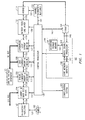
- FIG. 1 is a simplified block diagram of a universal line card 100 serving subscriber line 101. Subscriber line 101 is interconnected to customer premises equipment 103. Universal line card 100 includes core circuitry comprising overvoltage protection element 102, test element 104, ringing current function 106 interconnected to ringing voltage generator 107, coin current function 108, supervision loop current monitor 110, battery feed/line driver 112 and hybrid element 114. The various BORSCHT functional elements of the core circuit are interconnected via bi-directional links 115A through 115G.
- variable termination impedance function 122 which is interconnected to hybrid element 114 via link 123 and to the control processor described below.
- Codec functionality is contained in circuit 124 which is interconnected to hybrid function 114, control processor 130 and processing system 140.
- Control processor 130 is linked to test element 104, ring element 106, coin current element 108, supervision element 110 and battery element 112 via links 131, 133, 135, 137 and 139, respectively. Control processor 130 is also interconnected to variable termination impedance element 122 and codec 124 via links 141 and 143, respectively.
- Control processor 130 is also interconnected to configuration system 200 which provisions the subscriber loop standard line cards.
- control processor 130 is shown interconnected to a single line card but in alternative embodiments, this control processor serves a plurality of line card units.
- control processor 130 determines which elements and protocol should be deployed for the requested subscriber loop standard for a particular line circuit or line card. For example, configuration of a line card to operate in an ISDN mode would require processing system 140 to use an ISDN operating protocol (e.g., ISDN specific bit rates, bandwidth tolerances).
- the ISDN protocol also requires disabling elements 106, 108, 110 of the core circuitry and enabling and configuring elements 102, 104, 112, 114, 122, 124 and 140.
- control processor 130 Upon receiving instructions for ISDN operation of a line card, control processor 130 issues a command to processing system 140 which adopts the appropriate protocols and initiates enablement/disablement of elements in the line card.
- Processing system 140 includes digital signal processor 142 interconnected to algorithm storage memory 144 and core network interface 146 via bi-directional links 145 and 147, respectively.
- Digital signal processor 142 is also interconnected to codec circuit 124 via bi-directional link 149.
- algorithm storage memory 144 stores operational protocols associated with the various subscriber loop standards which the universal line card can deploy. More particularly, digital signal processor 142 operates at different speeds (that is, different bit rates and processing speed) depending on the type of subscriber loop standard being deployed by the universal line card which it serves.
- Algorithm storage memory 144 stores the various protocols associated with each subscriber loop standard and directs a digital signal processor with appropriate instructions.
- the digital signal processor serves a plurality of line cards. Transmissions to the core (or serving telecommunications network) are accomplished via link 147 which could also serve a plurality of line cards.
- FIG. 2 is a more detailed block diagram of a configuration system which serves a plurality of line cards, including universal line card 100 shown in FIG. 1.
- configuration system 200 is interconnected to control processor 130 via link 203.
- Link 203 carries all transmission and requirements issued by the configuration system, and also transmits alarm signals and requests from the universal line card to the configuration system via control processor 130.
- Configuration system 200 comprises central processor 202 interconnected to database 204 via link 205 and a plurality of network interfaces 210, 212 and 214 which are linked to the processor via links 211, 213 and 215, respectively.
- interface 214 is a trunk interface with DTMF processing capability.
- the configuration system receives input from a plurality of sources.
- an end user at personal computer 240 may access the system via a third party server, such as third party host server 220 interconnected to the configuration system via link 221.
- a telecommunications service provider technician may remotely provision and maintain line cards via workstation access to the configuration system.
- workstation 224 is interconnected to the configuration system via link 225 and interface 212.
- the configuration system may be remotely accessed via the public switched telephone network (PSTN) and trunk interface 214.
- PSTN public switched telephone network
- a call from telephone 260 may be placed to configuration system trunk interface 214 via PSTN to input instructions for changing the configuration of a particular universal line card.
- DTMF tones may be used to identify a particular line card and issue responses to a menu driven provisioning protocol so that an end user may request and effect changes to subscriber line services.
- the universal line card can also automatically issue changes when errors or operational problems are detected. For example, if a particular line card is to operate in ADSL mode but some malfunction is occurring, the line card can issue a default mode operation request to the configuration system via the control processor so that the line card can be temporarily configured to operate in POTS mode until the malfunction is corrected. In this manner, configuration system 200 works in conjunction with universal line card 100 to create an intelligent provisioning and operational system which requires minimal labor for maintenance and provisioning.
- FIG. 3 is a flow diagram illustrating the steps performed by configuration system 200 as shown in FIG. 2 to accommodate a subscriber loop standard change request.
- step 300 the configuration system receives a provisioning request for relating to a universal line card which it serves.
- the provisioning request may enter the configuration system via one of a plurality of interfaces such as end user interface 210, telecommunications service provider interface 212, or PSTN interface 214.
- decision step 302 the configuration system determines whether the universal line card identified in the provisioning request is served by this system. If the outcome of decision step 302 is a "NO" determination, the process continues to step 303 in which an error message is provided to the requester. If the outcome of decision step 302 is a "YES" determination, the process continues to step 304 in which the configuration system accesses its internal database for verifying that the requested service can be provided on the universal line card.
- the configuration system processor issues a command to the control processor associated with the identified universal line card (e.g., control processor 130) including instructions for effecting the requested change.
- the command includes configuration instructions for the codec, core network interface and call processing functions.
- the control processor issues the command to the processing system serving the universal line card requesting that a particular subscriber loop standard be implemented on the identified line card.
- the control processor receives confirmation from the processing system that the subscriber loop standard has been implemented.
- the control processor sends a process complete message to the configuration system indicating that the requested provisioning has been accomplished.
- the configuration system issues a provisioning complete message to the requester indicating that the provisioning and maintenance of the identified line card has been accomplished.
- a telecommunications service provider technician is not required to physically access a line card for altering the subscriber loop standard in which the line card operates.
- the universal line card is capable of identifying malfunctions and automatically operating in a default mode when such malfunctions arise.
- the convenience associated with end user capability for universal line card provisioning may also contribute to enhanced efficiency for the telecommunications service provider.
Landscapes
- Engineering & Computer Science (AREA)
- Signal Processing (AREA)
- Interface Circuits In Exchanges (AREA)
- Telephonic Communication Services (AREA)
Abstract
Description
Claims (13)
- A universal line card comprising:core circuitry for performing battery, overvoltage, ringing, supervision, coder/decoder circuit (CODEC), hybrid and test (BORSCHT) functions;a control processor interconnected to selected BORSCHT function circuitry for controlling such circuitry; anda processing system interconnected to the control processor and a coder/decoder circuit (codec) for operating the line card according to at least two subscriber loop standards.
- The universal line card of claim 1 wherein the control processor serves a plurality of universal line cards.
- The universal line card of claim 1 wherein the processing system and codec serves a plurality of universal line cards.
- The universal line card of claim 1 wherein the processing system includes a digital signal processor capable of operating in accordance with each of the subscriber loop standards.
- The universal line card of claim 1 further comprising a memory for storing algorithms relating to the various protocols associated with the subscriber loop standards in which the line card can operate.
- The universal line card of claim 1 further comprising an interface to a core network for establishing connections between customer premises equipment served by the universal line card and the public switched telephone network.
- The universal line card of claim 1 wherein the subscriber loop standards are selected from a group including POTS, ISDN, coin, HDSL, ADSL, VDSL, SDSL and 10 base T.
- The universal line card of claim 6 wherein the interface is a circuit interface.
- The universal line card of claim 6 wherein the interface is a packet interface.
- A configuration system for provisioning a universal telecommunications line card comprising:a link interconnecting the configuration system to a control processor serving the universal telecommunications line card;means for receiving input for provisioning changes associated with a particular line card, wherein the input may come via a data network or the public switched telephone network; andmeans for receiving updates from the telecommunications line card.
- A method for altering a telecommunications line card comprising the steps of:receiving a request for a provisioning change;a configuring system accessing a control processor associated with the line card identified in the request for forwarding instructions relating to the requested change;the configuration receiving confirmation that the provisioning request has been accomplished.
- The method of claim 11 further comprising the control processor accessing a processing system for issuing commands relating to the activation of protocols associated with the requested provisioning change; and
receiving confirmation from the processing system that the changes have been effected. - The method of claim 11 further comprising configuring the telecommunications line card with a plurality of subscriber loop standards.
Applications Claiming Priority (2)
| Application Number | Priority Date | Filing Date | Title |
|---|---|---|---|
| US519813 | 2000-03-06 | ||
| US09/519,813 US6694015B1 (en) | 2000-03-06 | 2000-03-06 | Universal line interface in telecommunications system |
Publications (3)
| Publication Number | Publication Date |
|---|---|
| EP1133137A2 true EP1133137A2 (en) | 2001-09-12 |
| EP1133137A3 EP1133137A3 (en) | 2001-10-17 |
| EP1133137B1 EP1133137B1 (en) | 2003-11-12 |
Family
ID=24069885
Family Applications (1)
| Application Number | Title | Priority Date | Filing Date |
|---|---|---|---|
| EP00308102A Expired - Lifetime EP1133137B1 (en) | 2000-03-06 | 2000-09-18 | Universal line interface in telecommunications system |
Country Status (3)
| Country | Link |
|---|---|
| US (1) | US6694015B1 (en) |
| EP (1) | EP1133137B1 (en) |
| DE (1) | DE60006482T2 (en) |
Cited By (2)
| Publication number | Priority date | Publication date | Assignee | Title |
|---|---|---|---|---|
| FR2870069A1 (en) * | 2004-05-04 | 2005-11-11 | Alcatel Sa | Analog telephone line equipment testing method, involves opening line test relay to isolate line equipment and closing ringing relay to apply ringing signal such that input amplifier is saturated for generating high level harmonics |
| EP1858287A1 (en) | 2006-05-16 | 2007-11-21 | Huawei Technologies Co., Ltd. | A multimode Xdsl line card adaptive activation method and its system |
Families Citing this family (3)
| Publication number | Priority date | Publication date | Assignee | Title |
|---|---|---|---|---|
| EP1053629B1 (en) * | 1998-02-05 | 2002-05-02 | Siemens Aktiengesellschaft | Method for processing telephone signals delivered by an analog telephone terminal and data delivered by a data terminal |
| JP3748723B2 (en) * | 1998-11-24 | 2006-02-22 | 富士通株式会社 | Common package |
| CN108933601B (en) * | 2017-05-23 | 2020-06-19 | 宁德时代新能源科技股份有限公司 | Coding chip and battery monitoring unit |
Family Cites Families (10)
| Publication number | Priority date | Publication date | Assignee | Title |
|---|---|---|---|---|
| US5088089A (en) * | 1989-12-15 | 1992-02-11 | Alcatel Na Network Systems Corp. | Apparatus for programmably accessing and assigning time slots in a time division multiplexed communication system |
| US5253291A (en) * | 1990-10-18 | 1993-10-12 | Ag Communication Systems Corporation | Hybrid balance and combination codec filter circuit |
| US5267309A (en) * | 1990-11-20 | 1993-11-30 | Alcatel Network Systems, Inc. | Telephone line unit having programmable read-only memory |
| JPH04280597A (en) | 1991-03-08 | 1992-10-06 | Nec Corp | Subscriber circuit |
| US5323460A (en) * | 1992-01-07 | 1994-06-21 | Ag Communication Systems Corporation | Enhanced subscriber line interface circuit |
| US5500894A (en) | 1993-12-03 | 1996-03-19 | Silicon Systems, Inc. | Telephone line interface with AC and DC transconductance loops |
| US5881129A (en) * | 1996-05-10 | 1999-03-09 | Chen; Robert Kuo-Wei | Self-monitoring line interface circuit |
| US6195414B1 (en) * | 1997-04-17 | 2001-02-27 | Telecom Analysis Systems | Digital facility simulator with CODEC emulation |
| US6396922B1 (en) | 1997-12-30 | 2002-05-28 | Alcatel Usa Sourcing, L.P. | Telecommunications terminal card |
| US6507585B1 (en) * | 1998-05-27 | 2003-01-14 | 3Com Corporation | Multi-carrier LAN adapter device using frequency domain equalizer |
-
2000
- 2000-03-06 US US09/519,813 patent/US6694015B1/en not_active Expired - Lifetime
- 2000-09-18 DE DE60006482T patent/DE60006482T2/en not_active Expired - Lifetime
- 2000-09-18 EP EP00308102A patent/EP1133137B1/en not_active Expired - Lifetime
Cited By (3)
| Publication number | Priority date | Publication date | Assignee | Title |
|---|---|---|---|---|
| FR2870069A1 (en) * | 2004-05-04 | 2005-11-11 | Alcatel Sa | Analog telephone line equipment testing method, involves opening line test relay to isolate line equipment and closing ringing relay to apply ringing signal such that input amplifier is saturated for generating high level harmonics |
| EP1858287A1 (en) | 2006-05-16 | 2007-11-21 | Huawei Technologies Co., Ltd. | A multimode Xdsl line card adaptive activation method and its system |
| US7672449B2 (en) | 2006-05-16 | 2010-03-02 | Huawei Technologies Co., Ltd. | Multimode xDSL line card adaptive activation method and its system |
Also Published As
| Publication number | Publication date |
|---|---|
| EP1133137B1 (en) | 2003-11-12 |
| DE60006482D1 (en) | 2003-12-18 |
| EP1133137A3 (en) | 2001-10-17 |
| US6694015B1 (en) | 2004-02-17 |
| DE60006482T2 (en) | 2004-09-09 |
Similar Documents
| Publication | Publication Date | Title |
|---|---|---|
| US5668857A (en) | Communication server apparatus and method | |
| US6385203B2 (en) | Communication server apparatus and method | |
| US6160843A (en) | Communication server apparatus providing XDSL services and method | |
| US5898761A (en) | Communication server apparatus using digital signal switching and method | |
| US6169788B1 (en) | Communication server apparatus having distributed switching and method | |
| US5999526A (en) | Method and apparatus for delivering data from an information provider using the public switched network | |
| US5812656A (en) | System for providing prioritized connections in a public switched network | |
| US5905781A (en) | Communication server apparatus and method | |
| US5781617A (en) | Communication server apparatus using frequency multiplexing and method | |
| US6014431A (en) | Communication server apparatus having four-wire switching interface and method | |
| US5086461A (en) | Apparatus and method for providing existing 1ESS and 1AESS telephone switching equipment with the capability of using the SS7 protocol | |
| US6738470B1 (en) | Distributed gateway system for telephone communications | |
| WO1997037458A2 (en) | Communication server apparatus and method | |
| JP4377094B2 (en) | Line card for communication system, method for supporting POTS and asymmetric DS line service and symmetric DS line service based on line card | |
| US6072793A (en) | Electronically controlled main distributing frame | |
| US5995601A (en) | Automatic remote meter reading system and method employing selectable line interface | |
| US5905782A (en) | Facsimile jack for selectively routing transmissions through a facsimile network | |
| US6163599A (en) | Communication server apparatus and method | |
| US20020131401A1 (en) | Sharing remote terminals | |
| AU760623B2 (en) | Local switch | |
| US6694015B1 (en) | Universal line interface in telecommunications system | |
| US5802155A (en) | Method and apparatus for controlling regular and supressed ringing connections in a telecommunications network | |
| EP1021029B1 (en) | Telecommunication network with remotely controllable, line multi-interface and telecommunication method | |
| US6674764B1 (en) | Communications system and method with telemetry device identification capabilities | |
| US6038297A (en) | System for party line suppressed ringing access of subscriber lines |
Legal Events
| Date | Code | Title | Description |
|---|---|---|---|
| PUAI | Public reference made under article 153(3) epc to a published international application that has entered the european phase |
Free format text: ORIGINAL CODE: 0009012 |
|
| PUAL | Search report despatched |
Free format text: ORIGINAL CODE: 0009013 |
|
| 17P | Request for examination filed |
Effective date: 20001003 |
|
| AK | Designated contracting states |
Kind code of ref document: A2 Designated state(s): AT BE CH CY DE DK ES FI FR GB GR IE IT LI LU MC NL PT SE Kind code of ref document: A2 Designated state(s): DE FR GB |
|
| AX | Request for extension of the european patent |
Free format text: AL;LT;LV;MK;RO;SI |
|
| AK | Designated contracting states |
Kind code of ref document: A3 Designated state(s): AT BE CH CY DE DK ES FI FR GB GR IE IT LI LU MC NL PT SE |
|
| AX | Request for extension of the european patent |
Free format text: AL;LT;LV;MK;RO;SI |
|
| 17Q | First examination report despatched |
Effective date: 20011127 |
|
| AKX | Designation fees paid |
Free format text: DE FR GB |
|
| GRAH | Despatch of communication of intention to grant a patent |
Free format text: ORIGINAL CODE: EPIDOS IGRA |
|
| GRAS | Grant fee paid |
Free format text: ORIGINAL CODE: EPIDOSNIGR3 |
|
| GRAA | (expected) grant |
Free format text: ORIGINAL CODE: 0009210 |
|
| AK | Designated contracting states |
Kind code of ref document: B1 Designated state(s): DE FR GB |
|
| REG | Reference to a national code |
Ref country code: GB Ref legal event code: FG4D |
|
| REF | Corresponds to: |
Ref document number: 60006482 Country of ref document: DE Date of ref document: 20031218 Kind code of ref document: P |
|
| ET | Fr: translation filed | ||
| PLBE | No opposition filed within time limit |
Free format text: ORIGINAL CODE: 0009261 |
|
| STAA | Information on the status of an ep patent application or granted ep patent |
Free format text: STATUS: NO OPPOSITION FILED WITHIN TIME LIMIT |
|
| 26N | No opposition filed |
Effective date: 20040813 |
|
| REG | Reference to a national code |
Ref country code: GB Ref legal event code: 732E Free format text: REGISTERED BETWEEN 20131107 AND 20131113 |
|
| REG | Reference to a national code |
Ref country code: FR Ref legal event code: CD Owner name: ALCATEL-LUCENT USA INC. Effective date: 20131122 |
|
| REG | Reference to a national code |
Ref country code: FR Ref legal event code: GC Effective date: 20140410 |
|
| REG | Reference to a national code |
Ref country code: FR Ref legal event code: RG Effective date: 20141015 |
|
| REG | Reference to a national code |
Ref country code: FR Ref legal event code: PLFP Year of fee payment: 16 |
|
| REG | Reference to a national code |
Ref country code: FR Ref legal event code: PLFP Year of fee payment: 17 |
|
| PGFP | Annual fee paid to national office [announced via postgrant information from national office to epo] |
Ref country code: GB Payment date: 20160920 Year of fee payment: 17 Ref country code: DE Payment date: 20160921 Year of fee payment: 17 |
|
| PGFP | Annual fee paid to national office [announced via postgrant information from national office to epo] |
Ref country code: FR Payment date: 20160921 Year of fee payment: 17 |
|
| REG | Reference to a national code |
Ref country code: DE Ref legal event code: R119 Ref document number: 60006482 Country of ref document: DE |
|
| GBPC | Gb: european patent ceased through non-payment of renewal fee |
Effective date: 20170918 |
|
| REG | Reference to a national code |
Ref country code: FR Ref legal event code: ST Effective date: 20180531 |
|
| PG25 | Lapsed in a contracting state [announced via postgrant information from national office to epo] |
Ref country code: GB Free format text: LAPSE BECAUSE OF NON-PAYMENT OF DUE FEES Effective date: 20170918 Ref country code: DE Free format text: LAPSE BECAUSE OF NON-PAYMENT OF DUE FEES Effective date: 20180404 |
|
| PG25 | Lapsed in a contracting state [announced via postgrant information from national office to epo] |
Ref country code: FR Free format text: LAPSE BECAUSE OF NON-PAYMENT OF DUE FEES Effective date: 20171002 |
|
| REG | Reference to a national code |
Ref country code: DE Ref legal event code: R081 Ref document number: 60006482 Country of ref document: DE Owner name: WSOU INVESTMENTS, LLC, LOS ANGELES, US Free format text: FORMER OWNER: LUCENT TECHNOLOGIES INC., MURRAY HILL, N.J., US |
|
| REG | Reference to a national code |
Ref country code: GB Ref legal event code: 732E Free format text: REGISTERED BETWEEN 20201001 AND 20201007 |