EP1133006A2 - Electrical connection box containing bus bars - Google Patents
Electrical connection box containing bus bars Download PDFInfo
- Publication number
- EP1133006A2 EP1133006A2 EP01300550A EP01300550A EP1133006A2 EP 1133006 A2 EP1133006 A2 EP 1133006A2 EP 01300550 A EP01300550 A EP 01300550A EP 01300550 A EP01300550 A EP 01300550A EP 1133006 A2 EP1133006 A2 EP 1133006A2
- Authority
- EP
- European Patent Office
- Prior art keywords
- bus bars
- casings
- bars
- connection box
- electrical connection
- Prior art date
- Legal status (The legal status is an assumption and is not a legal conclusion. Google has not performed a legal analysis and makes no representation as to the accuracy of the status listed.)
- Withdrawn
Links
- 238000009434 installation Methods 0.000 description 5
- 239000000463 material Substances 0.000 description 4
- 230000002950 deficient Effects 0.000 description 3
- 238000006243 chemical reaction Methods 0.000 description 2
- 238000010276 construction Methods 0.000 description 2
- 230000000694 effects Effects 0.000 description 2
- 239000002184 metal Substances 0.000 description 2
- 238000012986 modification Methods 0.000 description 2
- 230000004048 modification Effects 0.000 description 2
- 239000004743 Polypropylene Substances 0.000 description 1
- 230000002159 abnormal effect Effects 0.000 description 1
- 230000004308 accommodation Effects 0.000 description 1
- 238000005452 bending Methods 0.000 description 1
- 230000000994 depressogenic effect Effects 0.000 description 1
- 230000005489 elastic deformation Effects 0.000 description 1
- 230000008030 elimination Effects 0.000 description 1
- 238000003379 elimination reaction Methods 0.000 description 1
- 238000003780 insertion Methods 0.000 description 1
- 230000037431 insertion Effects 0.000 description 1
- 239000004033 plastic Substances 0.000 description 1
- 229920003023 plastic Polymers 0.000 description 1
- -1 polypropylene Polymers 0.000 description 1
- 229920001155 polypropylene Polymers 0.000 description 1
- 238000004080 punching Methods 0.000 description 1
- 229920003002 synthetic resin Polymers 0.000 description 1
- 239000000057 synthetic resin Substances 0.000 description 1
- 239000000454 talc Substances 0.000 description 1
- 229910052623 talc Inorganic materials 0.000 description 1
Images



Classifications
-
- H—ELECTRICITY
- H01—ELECTRIC ELEMENTS
- H01R—ELECTRICALLY-CONDUCTIVE CONNECTIONS; STRUCTURAL ASSOCIATIONS OF A PLURALITY OF MUTUALLY-INSULATED ELECTRICAL CONNECTING ELEMENTS; COUPLING DEVICES; CURRENT COLLECTORS
- H01R9/00—Structural associations of a plurality of mutually-insulated electrical connecting elements, e.g. terminal strips or terminal blocks; Terminals or binding posts mounted upon a base or in a case; Bases therefor
- H01R9/22—Bases, e.g. strip, block, panel
- H01R9/24—Terminal blocks
- H01R9/2458—Electrical interconnections between terminal blocks
Definitions
- the present invention relates to an electrical connection box containing bus bars, particularly such a box which is suitable for use in a vehicle, e.g. an automobile.
- USA Patent 5624280 discloses an electrical branch joint box having identical upper and lower casings in which an array of upright sheet bus bars is mounted, with terminals of the bus bars projecting through the casings into connector sockets at the exterior face of the casings.
- the casings have mutually engageable snap-fit locking components, to lock them together in the assembled condition with the bus bars held between them.
- Figs. 8 and 9 of the present drawings illustrate diagrammatically a problem which arises with casings of such an electrical connection box having snap-fit locking components.
- the box 51 has an upper casing 52 and a lower casing 53. Wires and the like are accommodated in each of the upper and lower casings 52,53.
- Locking projections 54 are formed at the lower edge of the outer side surface of the upper casing 52. At the upper edge of the outer side surface of the lower casing 53, there are locking recesses 55 in which the projections 54 fit. Fitting of the projections 54 in the recesses 55 allows the upper and lower casings 52,53 to be fixedly joined to each other.
- the projection 54 is able to enter the recess 55 owing to its elastic deformation in a direction shown by an arrow F. To allow this reliably, it is necessary to provide a predetermined clearance amount C between the projection 54 and a part of the recess 55. Accordingly, there is looseness or play between the upper casing 52 and the lower casing 53 in correspondence to the length of the clearance C. As a result, due to vibrations generated during travel of a vehicle, the projection 54 and the recess 55 rub against each other to generate abnormal sounds.
- an electrical connection box having an upper casing, a lower casing and mutually engageable locking components on the upper and lower casings for locking the casings together in an assembled condition, the casings defining an interior space when in the assembled condition.
- a plurality of bus bars are mounted upright in the interior space.
- At least one of the casings has at least one abutment pressing on the bus bars, when the casings are in the assembled condition and the locking components are engaged, in a manner so as to maintain the bus bars in position and so that the bus bars urge the casings apart against the restraint of the locking components.
- the abutment or abutments pressing the bus bars are preferably projections or narrow rib-like bars, achieving contact with the bus bars at a small area, in order to provide a pressing force eliminating looseness and play.
- the bus bars have main elongate body portions of flat shape arranged upright in an array alongside each other and extending parallel to each other in a longitudinal direction, and the box has a plurality of the abutments in the form of elongate members each extending across the array of bus bars perpendicularly to the longitudinal direction of the bus bars, the members being spaced apart along the length of the bus bars.
- the reaction force generated by the engagement of the abutment or abutments and the bus bars urges the upper and lower casings apart. This prevents the generation of looseness or play at the locking components although a clearance is provided between the locking components .
- the natural resilience and/or flexibility of the material of the casings permits the locking components to engage each other, while also allowing the bus bars to press the casings apart so as to eliminate looseness. Therefore, it is possible to prevent the generation of looseness between the first and second casings.
- the engagement force between the upright bus bars and the abutment or abutments thus also acts to prevent the bus bars from being loose in the casings.
- the bus bars can be reliably and immovably accommodated at predetermined positions in the casings.
- the casings are typically made of a suitable electrically insulating plastics material having an inherent slight deformability.
- a plurality of abutments are arranged to act on the bus bars and extend transversely to the bus bar array and are disposed at predetermined intervals over the entire length of the bus bars, the array of bus bars are uniformly pressed in position, and the casings are urged apart in a balanced manner.
- Pressure connection blades may be formed on the vertical bus bars, so that by pressing an electrical wire against the pressure connection blades of adjacent or spaced bus bars, the bus bars can be electrically connected to each other. In this way, it is easy to electrically connect the bus bars; and it is easy to design or alter a bus bar circuit.
- bus bars are prevented from loosening, it is also possible to prevent the electric wire from being separated from the pressure connection blade. Accordingly, it is possible to improve the reliability of the connection between electrical wires and the bus bars.
- the invention also extends to use of the electrical connection box in a vehicle, e.g. automobile.
- an electric connection box 11 embodying the invention has an outer case constructed of an upper casing 12 (first casing) and a lower casing 13 (second casing) and an array 14 of bus bars housed in the casings.
- the upper casing 12 and the lower casing 13 are made in one-piece of molded synthetic resin and formed so that they fit to each other. More specifically, locking projections 12a are formed on outer side surfaces of the upper casing 12, and on inner side surfaces of the lower casing 13 there are molded shapes providing locking recesses 13a capable of receiving and locking in a snap-fit manner with the respective projections 12a, to unite the upper and lower casings 12,13.
- the material of the casings 12,13 in this embodiment is PPT (polypropylene + talc).
- the array 14 of the bus bars is comprised of ten bus bars 15a-15j each consisting of a one-piece metal plate or sheet lying vertically.
- the bus bars 15a-15j all have the same shape and configuration and are formed by punching and bending sheet metal.
- each of the bus bars 15a-15j is constructed of a plate-shaped planar main body 21, a plurality of tab terminals 22, and a plurality of pressure connection blades 23.
- the tab terminals 22 project from the upper side of the body 21 at regular intervals.
- the pressure connection blades 23 project at regular intervals from the lower side of the body 21, and each is spaced along the body 21 from the adjacent tab terminals 22. That is, the blade 23 is not formed at a longitudinal position corresponding to that of the tab terminal.
- the tab terminals 22 and the blades 23 are alternately formed along the body 21.
- a plurality of projections 21a are provided at regular intervals on the lower side of the body 21 at positions corresponding to the tab terminal positions.
- the length of the lower edge of each projection 21a is larger than the width of a ridge or bar 27 of the lower casing 13, which will be described later.
- a plurality of connector-receiving housings 4 for installation of components are formed integrally on the upper side of the upper casing 12.
- grooves 25 capable of accommodating the bus bars 15a-15j are formed on the lower side of the upper casing 12, parallel with one another and spaced at regular intervals.
- bus bar accommodation grooves 26 are formed on the upper side of the lower casing 13 at positions corresponding to the grooves 25.
- linear ridges or bars 27 extend perpendicularly to the grooves 26 and are formed at regular intervals parallel with one another. The bars 27 are at positions corresponding to the positions of the projections 21a of the bus bars 15a-15j when assembled in the grooves 25.
- the bus bars 15a-15j are accommodated in the grooves 25, with the tab terminals 22 projecting upwards.
- the main bodies 21 of the bus bars 15a-15j are perpendicular to the bottom surface of the upper casing 12.
- the terminals 22 project through through-holes 24a formed through the bottom surface of each of the connector housings 24, while the projections 21a and the pressure connection blades 23 are located in rows perpendicular to the extension direction of the main bodies 21 of the bus bars.
- the wire core is trapped in and electrically contacts the slots of the blades 23 (see Fig. 7).
- the desired bus bars 15a-15j are electrically connected to one another.
- the wires 31 can run linearly in a direction perpendicular to the extension direction of the bodies 21.
- the bus bars 15a-15c and the bus bars 15g-15i are electrically connected to each other respectively, by the two wires 31.
- the lower casing 13 is installed on the bottom face of the upper casing 12.
- the upper and lower casings 12,13 are non-removably combined with each other by fitting the locking projections 12a of the upper casing 12 on the recesses 13a of the lower casing 13.
- the locking components 12a,13a have an amount of clearance C (see Fig. 5) to permit them to be fitted together.
- the bars 27 of the lower casing 13 press the projections 21a of the bus bars 15a-15j. More specifically, as shown in Fig.
- each bar 27 is higher than the lower edge of the projections 21a by a small amount hl (0.2mm in the embodiment). Therefore, each bar 27 is slightly deformed by the projections 21a at their contact points.
- the natural resilience of the material of the casings maintains a tight contact of the bars 27 during use. Consequently, as shown with the arrow V1 of Fig. 5, the bus bars 15a-15j are urged upward by the force applied by the bars 27, and the lower casing 13 is urged downward by the reaction force, as shown with the arrow V2 of Fig. 5.
- the upper casing 12 is urged upward by the bus bars 15a-15j.
- the upper and lower casings 12,13 are urged apart eliminating any play or looseness at the locking components.
- Fig. 5 shows, mutually abutting faces of the locking components are pressed together to restrain the casings from moving apart.
- bus bar circuit it is possible to alter the bus bar circuit as desired for a particular use, by cutting off parts of the bus bars 15a-15j.
- the body 21 is cut at positions shown by broken lines C1 in Fig. 6, so that the bus bar now consists of two electrically divided component parts.
- Various bus bar circuits can thus be obtained, e.g. as shown in Fig. 7.
Landscapes
- Connection Or Junction Boxes (AREA)
Abstract
An electrical connection box has upper and lower casing (12,13) and locking components (12a,13a) for locking the casings together in an assembled condition. An array of bus bars (15) are mounted upright in the interior space of the casings. At least one of the casings has abutments (27) pressing on the bus bars so as to maintain the bus bars in position and so that the bus bars urge the casings apart against the restraint of the locking components.
Description
- The present invention relates to an electrical connection box containing bus bars, particularly such a box which is suitable for use in a vehicle, e.g. an automobile.
- USA Patent 5624280 discloses an electrical branch joint box having identical upper and lower casings in which an array of upright sheet bus bars is mounted, with terminals of the bus bars projecting through the casings into connector sockets at the exterior face of the casings. The casings have mutually engageable snap-fit locking components, to lock them together in the assembled condition with the bus bars held between them.
- Figs. 8 and 9 of the present drawings illustrate diagrammatically a problem which arises with casings of such an electrical connection box having snap-fit locking components. In Fig. 8, the
box 51 has anupper casing 52 and alower casing 53. Wires and the like are accommodated in each of the upper andlower casings Locking projections 54 are formed at the lower edge of the outer side surface of theupper casing 52. At the upper edge of the outer side surface of thelower casing 53, there arelocking recesses 55 in which theprojections 54 fit. Fitting of theprojections 54 in therecesses 55 allows the upper andlower casings - However, as shown in Fig. 9, the
projection 54 is able to enter therecess 55 owing to its elastic deformation in a direction shown by an arrow F. To allow this reliably, it is necessary to provide a predetermined clearance amount C between theprojection 54 and a part of therecess 55. Accordingly, there is looseness or play between theupper casing 52 and thelower casing 53 in correspondence to the length of the clearance C. As a result, due to vibrations generated during travel of a vehicle, theprojection 54 and the recess 55 rub against each other to generate abnormal sounds. - In an electrical connection box having vertical bus bars disclosed in JP-A-7-135717, two casing are joined by fitting them together. As described above, looseness is generated between the two casings, which causes the vertical bus bars accommodated in the box to loosen. Therefore, due to vibration of the vehicle, there is a possibility that contact of tabs of the vertical bus bars and electric component parts connected to the tabs becomes defective.
- It is an object of the present invention to provide an electrical connection box capable of minimizing or avoiding such looseness between upper and lower casings and looseness of the bus bars.
- According to the invention, there is provided an electrical connection box having an upper casing, a lower casing and mutually engageable locking components on the upper and lower casings for locking the casings together in an assembled condition, the casings defining an interior space when in the assembled condition. A plurality of bus bars are mounted upright in the interior space. At least one of the casings has at least one abutment pressing on the bus bars, when the casings are in the assembled condition and the locking components are engaged, in a manner so as to maintain the bus bars in position and so that the bus bars urge the casings apart against the restraint of the locking components.
- The abutment or abutments pressing the bus bars are preferably projections or narrow rib-like bars, achieving contact with the bus bars at a small area, in order to provide a pressing force eliminating looseness and play.
- In a preferred embodiment the bus bars have main elongate body portions of flat shape arranged upright in an array alongside each other and extending parallel to each other in a longitudinal direction, and the box has a plurality of the abutments in the form of elongate members each extending across the array of bus bars perpendicularly to the longitudinal direction of the bus bars, the members being spaced apart along the length of the bus bars.
- In the invention, the reaction force generated by the engagement of the abutment or abutments and the bus bars urges the upper and lower casings apart. This prevents the generation of looseness or play at the locking components although a clearance is provided between the locking components . The natural resilience and/or flexibility of the material of the casings permits the locking components to engage each other, while also allowing the bus bars to press the casings apart so as to eliminate looseness. Therefore, it is possible to prevent the generation of looseness between the first and second casings. The engagement force between the upright bus bars and the abutment or abutments thus also acts to prevent the bus bars from being loose in the casings. Thus, the bus bars can be reliably and immovably accommodated at predetermined positions in the casings. The casings are typically made of a suitable electrically insulating plastics material having an inherent slight deformability.
- If a plurality of abutments are arranged to act on the bus bars and extend transversely to the bus bar array and are disposed at predetermined intervals over the entire length of the bus bars, the array of bus bars are uniformly pressed in position, and the casings are urged apart in a balanced manner.
- Pressure connection blades may be formed on the vertical bus bars, so that by pressing an electrical wire against the pressure connection blades of adjacent or spaced bus bars, the bus bars can be electrically connected to each other. In this way, it is easy to electrically connect the bus bars; and it is easy to design or alter a bus bar circuit.
- Since the bus bars are prevented from loosening, it is also possible to prevent the electric wire from being separated from the pressure connection blade. Accordingly, it is possible to improve the reliability of the connection between electrical wires and the bus bars.
- The invention also extends to use of the electrical connection box in a vehicle, e.g. automobile.
- In this specification, including the claims, the directional terms "upper", "lower" etc. are used solely for convenience and clarity of description and definition. It is to be understood that the electrical connection box of the invention can be assembled and used in any orientation.
- Embodiments of the invention will now be described by way of non-limitative example with reference to the accompanying drawings, in which:-
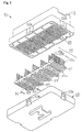
- Fig. 1 is an exploded perspective view of an electrical connection box which is an embodiment of the present invention.
- Fig. 2 is an exploded perspective view from below of the electrical connection box of Fig 1.
- Fig. 3 is a sectional view on line A-A of Fig. 1.
- Fig. 4 is a sectional view showing the assembled state of the electric connection box of Fig. 1.
- Fig. 5 is a sectional view of a part of Fig. 4 enlarged.
- Fig. 6 is a perspective view of a vertical bus bar of the box of Fig. 1, enlarged.
- Fig. 7 is a perspective view showing an example of a modification of the bus bar circuit in the box of Fig. 1.
- Fig. 8 is an exploded perspective view illustrating generally a problem of an electrical connection box having locking components .
- Fig. 9 is a partly enlarged sectional view taken along a line B-B of Fig. 8.
-
- As shown in Figs. 1 and 2, an
electric connection box 11 embodying the invention has an outer case constructed of an upper casing 12 (first casing) and a lower casing 13 (second casing) and anarray 14 of bus bars housed in the casings. Theupper casing 12 and thelower casing 13 are made in one-piece of molded synthetic resin and formed so that they fit to each other. More specifically,locking projections 12a are formed on outer side surfaces of theupper casing 12, and on inner side surfaces of thelower casing 13 there are molded shapes providinglocking recesses 13a capable of receiving and locking in a snap-fit manner with therespective projections 12a, to unite the upper andlower casings casings - The
array 14 of the bus bars is comprised of tenbus bars 15a-15j each consisting of a one-piece metal plate or sheet lying vertically. Thebus bars 15a-15j all have the same shape and configuration and are formed by punching and bending sheet metal. As also shown in Fig. 6, each of thebus bars 15a-15j is constructed of a plate-shaped planarmain body 21, a plurality oftab terminals 22, and a plurality ofpressure connection blades 23. Thetab terminals 22 project from the upper side of thebody 21 at regular intervals. The pressure connection blades 23 project at regular intervals from the lower side of thebody 21, and each is spaced along thebody 21 from theadjacent tab terminals 22. That is, theblade 23 is not formed at a longitudinal position corresponding to that of the tab terminal. Thetab terminals 22 and theblades 23 are alternately formed along thebody 21. A plurality ofprojections 21a are provided at regular intervals on the lower side of thebody 21 at positions corresponding to the tab terminal positions. The length of the lower edge of eachprojection 21a is larger than the width of a ridge orbar 27 of thelower casing 13, which will be described later. - As shown in Fig. 1, a plurality of connector-receiving housings 4 for installation of components are formed integrally on the upper side of the
upper casing 12. As shown in Fig. 2,grooves 25 capable of accommodating thebus bars 15a-15j are formed on the lower side of theupper casing 12, parallel with one another and spaced at regular intervals. - As shown in Fig. 1, bus
bar accommodation grooves 26 are formed on the upper side of thelower casing 13 at positions corresponding to thegrooves 25. On the upper surface of thelower casing 13, linear ridges or bars 27 extend perpendicularly to thegrooves 26 and are formed at regular intervals parallel with one another. Thebars 27 are at positions corresponding to the positions of theprojections 21a of the bus bars 15a-15j when assembled in thegrooves 25. - In the
electrical connection box 11 having the above-described construction, as shown in Figs. 1 to 4, the bus bars 15a-15j are accommodated in thegrooves 25, with thetab terminals 22 projecting upwards. Themain bodies 21 of the bus bars 15a-15j are perpendicular to the bottom surface of theupper casing 12. As shown in Figs. 3 to 5, theterminals 22 project through through-holes 24a formed through the bottom surface of each of theconnector housings 24, while theprojections 21a and thepressure connection blades 23 are located in rows perpendicular to the extension direction of themain bodies 21 of the bus bars. - When it is necessary to design a bus bar circuit by electrically connecting
different bus bars 15a-15j, anelectrical wire 31, e.g. a single-core wire, is pressed against the desiredpressure connection blades 23 by means of a pressing machine (not shown). The wire core is trapped in and electrically contacts the slots of the blades 23 (see Fig. 7). Thereby, the desiredbus bars 15a-15j are electrically connected to one another. Because theblades 23 are arranged in rows, thewires 31 can run linearly in a direction perpendicular to the extension direction of thebodies 21. In the embodiment, the bus bars 15a-15c and the bus bars 15g-15i are electrically connected to each other respectively, by the twowires 31. - The
lower casing 13 is installed on the bottom face of theupper casing 12. The upper andlower casings projections 12a of theupper casing 12 on therecesses 13a of thelower casing 13. The lockingcomponents lower casing 13 on theupper casing 12, as shown in Fig. 5, thebars 27 of thelower casing 13 press theprojections 21a of the bus bars 15a-15j. More specifically, as shown in Fig. 5, upon completion of the installation of thelower casing 13 on theupper casing 12, eachbar 27 is higher than the lower edge of theprojections 21a by a small amount hl (0.2mm in the embodiment). Therefore, eachbar 27 is slightly deformed by theprojections 21a at their contact points. The natural resilience of the material of the casings maintains a tight contact of thebars 27 during use. Consequently, as shown with the arrow V1 of Fig. 5, the bus bars 15a-15j are urged upward by the force applied by thebars 27, and thelower casing 13 is urged downward by the reaction force, as shown with the arrow V2 of Fig. 5. Theupper casing 12 is urged upward by the bus bars 15a-15j. Thus the upper andlower casings - It is possible to alter the bus bar circuit as desired for a particular use, by cutting off parts of the bus bars 15a-15j. For example the
body 21 is cut at positions shown by broken lines C1 in Fig. 6, so that the bus bar now consists of two electrically divided component parts. Various bus bar circuits can thus be obtained, e.g. as shown in Fig. 7. - When it is necessary to electrically connect bus bars which are spaced from each other, for example, the bus bars 15f and 15j,
pressure connection blade 23 of each of the bus bars 15g-15i is cut off, as shown in Fig. 7, e.g. eachblade 23 is cut off at a position shown with a broken line C2 in Fig. 6. In this case, thewire 31 is connected to theblades 23 of only the bus bars 15f and 15j. Thereby, it is possible to electrically connect the bus bars 15f and 15j to each other reliably. - Accordingly, the following effects can be obtained in this embodiment.
- (1) Upon fitting of the
projection 12a on therecess 13a, thebars 27 press the bus bars 15a-15j upward, so that the upper andlower casings lower casings projection 12a and therecess 13a. - (2) The pressing by the
bars 27 of the bus bars 15a-15j also prevents the bus bars 15a-15j from being loosein thebox 11. The bus bars are reliably held at predetermined positions in theelectric connection box 11. - (3) The
bars 27 extend in parallel at regular intervals in the direction perpendicular to the extension direction of the bus bars 15a-15j. Thus, all the bus bars 15a-15j are pressed by thebars 27. The upper andlower casings lower casings - (4) Each
bus bar 15a-15j haspressure connection blades 23. Thus, the bus bars 15a-15j can be electrically connected to each other in a simple manner throughelectric wires 31 by pressing thewires 31 against theblades 23. This eliminates the need for connection terminals on the wires which fit on thetab terminals 22, as in known electrical connection boxes. Thus, it is easy to electrically connect the bus bars 15a-15j. It is also easy to design or alter the bus bar circuit. Further, since the bus bars 15a-15j are prevented from becoming loos, it is possible to reduce the risk that thewire 31 is separated from theblade 23. Accordingly, it is possible to improve the reliability of the connection between theelectric wire 31 and the bus bars 15a-15j. - (5) A plurality of
projections 21a on each of the bus bars 15a-15j contact thebars 27. Therefore, it is possible to check the location state of the bus bars 15a-15j in the upper casing, e.g. by making the lower end of thebody 21 flush with the bottom surface of theupper casing 12, and thereby prevent defective positioning of the bus bars 15a-15j. If theprojections 21a project from the bottom surface of theupper casing 12, they can be reliably brought into contact with thebars 27. Further, because the length of the lower edges of theprojections 21a is larger than the width of thebars 27, thebar 27 can be reliably brought into contact with theprojections 21a. - (6) Each
projection 21a is at a position corresponding to the position of atab terminal 22, and is supported by one of thebars 27. Thus, even when an insertion force of an electrical component is applied to thetab terminal 22 upon installation of the electrical component, the risk that thetab terminal 22 is depressed in thecasings tab terminal 22. - (7) The top of the
bar 27 is higher than the lower edge of theprojection 21a by a small amount h1, e.g. 0.2mm, upon locking of thelower casing 13 to theupper casing 12. If this height h1 is too large, it may be difficult to fitprojection 12a in therecess 13a, whereas if the height h1 is too small, thebar 27 may not be deformed sufficiently for the desired effect. Thus, by setting the height h1 to 0.2mm in this example, it is possible to deform thebars 27 reliably, without making fitting of theprojection 12a in therecess 13a difficult. -
- The following variations of the embodiment may be mentioned:
- (1) In the embodiment, the
projections 21a are formed on the bus bars 15a-15j at positions to contact thebars 27. However, theprojections 21a may be omitted to allow each of the bus bars 15a-15j to have a more simple construction, with thebars 27 contacting thebodies 21 of the bus bars directly. - (2) In the embodiment, the
bars 27 formed on the upper surface of thelower casing 13 serve as the abutments. However, thebars 27 may be omitted and instead, abutments equivalent to thebars 27 may be formed on the bottom surface of theupper casing 12 to act as the abutment portions. That is, the abutments may be on theupper casing 12 or thelower casing 13. - (3) The abutment is not limited to the
bar 27. It is possible to form a narrow projection in correspondence to eachprojection 21a. - (4) In the embodiment, the locking
projections 12a are formed on theupper casing 12 and therecesses 13a on thelower casing 13. However, therecesses 13a may be on theupper casing 12 and the lockingprojection 12a on thelower casing 13. - (5) The
bar 27 is higher than the lower edge of theprojection 21a by a height hl of 0.2mm upon connection of thelower casing 13 on theupper casing 12 and elimination of play at the locking components. However, this height hl is not limited to 0.2mm, but for example may be in the range of 0.1 to 0.5mm. - (6) In the embodiment, the
tab terminals 22 are formed on only one side of thebody 21 of each of the bus bars 15a-15j. However, thetab terminals 22 may be formed on both sides of thebody 21. That is, each of the bus bars 15a-15j may have thetab terminal 22 extending vertically upwards and downwards from thebody 21. -
- While the invention has been described in conjunction with the exemplary embodiments described above, many equivalent modifications and variations will be apparent to those skilled in the art when given this disclosure. Accordingly, the exemplary embodiments of the invention set forth above are considered to be illustrative and not limiting. Various changes to the described embodiments may be made without departing from the spirit and scope of the invention.
Claims (3)
- An electrical connection box having an upper casing (12), a lower casing (13), mutually engageable locking components (12a,13a) on said casings for locking them together in an assembled condition, and a plurality of bus bars (15) mounted upright in an interior space in the assembled casings,
characterised in that:
at least one of said casings has at least one abutment (27) which, when said casings (12,13) are assembled together and said locking components are engaged, presses on said bus bars (15) in a manner so as to maintain said bus bars in position and so that said bus bars (15) urge said casings apart against the restraint of said locking components (12a,13a). - An electrical connection box according to claim 1, wherein said bus bars (15) have main elongate body portions (21) of flat shape arranged upright in an array alongside each other and extending parallel to each other in a longitudinal direction, and there are a plurality of said abutments (27) in the form of elongate members each extending across the array of bus bars perpendicularly to said longitudinal direction of said bus bars, said members (27) being spaced apart from each other along the length of said bus bars.
- An electrical connection box according to claim 1, wherein each said bus bar (15) has at its upper side at least one tab terminal (22) extending upwardly for connection in use to another electrical component, and has at its lower side at least one pressure connection blade (23) for connection to an electrical wire.
Applications Claiming Priority (2)
| Application Number | Priority Date | Filing Date | Title |
|---|---|---|---|
| JP2000017097 | 2000-01-26 | ||
| JP2000017097A JP3498663B2 (en) | 2000-01-26 | 2000-01-26 | Electrical junction box with vertical busbar |
Publications (1)
| Publication Number | Publication Date |
|---|---|
| EP1133006A2 true EP1133006A2 (en) | 2001-09-12 |
Family
ID=18544133
Family Applications (1)
| Application Number | Title | Priority Date | Filing Date |
|---|---|---|---|
| EP01300550A Withdrawn EP1133006A2 (en) | 2000-01-26 | 2001-01-22 | Electrical connection box containing bus bars |
Country Status (3)
| Country | Link |
|---|---|
| US (1) | US6471553B2 (en) |
| EP (1) | EP1133006A2 (en) |
| JP (1) | JP3498663B2 (en) |
Families Citing this family (6)
| Publication number | Priority date | Publication date | Assignee | Title |
|---|---|---|---|---|
| JP4054256B2 (en) * | 2002-12-19 | 2008-02-27 | 住友電装株式会社 | Junction box |
| JP2006311724A (en) * | 2005-04-28 | 2006-11-09 | Yazaki Corp | Electrical junction box |
| JP5756656B2 (en) * | 2011-03-04 | 2015-07-29 | 矢崎総業株式会社 | connector |
| US8662940B2 (en) | 2011-12-28 | 2014-03-04 | General Electric Company | Electrical connectors and methods for coupling the electrical connectors to busbars |
| US8690612B2 (en) | 2011-12-28 | 2014-04-08 | General Electric Company | Electrical connectors and methods for coupling the electrical connectors to busbars |
| US9337595B1 (en) * | 2014-10-15 | 2016-05-10 | Tyco Electronics Corporation | Busbar connection system |
Family Cites Families (7)
| Publication number | Priority date | Publication date | Assignee | Title |
|---|---|---|---|---|
| US5295847A (en) * | 1990-01-16 | 1994-03-22 | Yazaki Corporation | Branch junction box and busbars for branch connection |
| US5501605A (en) * | 1993-06-07 | 1996-03-26 | Yazaki Corporation | Wiring harness assembly for vehicles |
| US5490794A (en) * | 1993-11-05 | 1996-02-13 | Sumitomo Wiring Systems, Ltd. | Branch joint box |
| JP2833448B2 (en) | 1993-11-08 | 1998-12-09 | 住友電装株式会社 | Branch junction box containing busbar and busbar forming material |
| JP2929414B2 (en) | 1994-07-05 | 1999-08-03 | 矢崎総業株式会社 | Electrical junction box |
| JP3226211B2 (en) * | 1996-09-11 | 2001-11-05 | 矢崎総業株式会社 | Busbar wiring board |
| JP3473526B2 (en) | 1999-11-18 | 2003-12-08 | 住友電装株式会社 | Electrical junction box with vertical busbar |
-
2000
- 2000-01-26 JP JP2000017097A patent/JP3498663B2/en not_active Expired - Fee Related
-
2001
- 2001-01-22 EP EP01300550A patent/EP1133006A2/en not_active Withdrawn
- 2001-01-22 US US09/765,353 patent/US6471553B2/en not_active Expired - Fee Related
Also Published As
| Publication number | Publication date |
|---|---|
| US6471553B2 (en) | 2002-10-29 |
| JP2001211530A (en) | 2001-08-03 |
| JP3498663B2 (en) | 2004-02-16 |
| US20010009825A1 (en) | 2001-07-26 |
Similar Documents
| Publication | Publication Date | Title |
|---|---|---|
| US5822189A (en) | Electrical connection box, a connection construction, a busbar fixing construction and a connection terminal | |
| EP1130731B1 (en) | An electrical connection box for an automotive vehicle | |
| CN101552442B (en) | Bus bar mounting assembly | |
| US5011417A (en) | Structure of connection between bus bar and press-connecting branch terminal in electric connection box | |
| EP0829928B1 (en) | An electrical connection box | |
| US7320608B2 (en) | Electric distribution box and method of assembling the same | |
| US6780026B2 (en) | Electrical junction box | |
| EP1596471B1 (en) | Terminal arrangement of electrical apparatus | |
| US6870097B2 (en) | Electrical junction box | |
| US6468091B2 (en) | Electrical distribution center | |
| US6471553B2 (en) | Electrical connection box containing bus bars | |
| EP1102352B1 (en) | Electrical connection box containing bus bars | |
| CN111223730B (en) | Mounting structure between cover and housing and fusible connection unit | |
| US6299471B1 (en) | Press-connecting connector | |
| US6354864B1 (en) | Joint terminal and joint connector including said terminal | |
| US6368118B1 (en) | Electric connection box | |
| EP1718140A2 (en) | Electric connection box | |
| US6077110A (en) | Connector | |
| US6890209B2 (en) | Pressure welding terminal for plate connector | |
| EP1577982B1 (en) | Electrical junction box and continuity inspection jig assembly fitted on the electrical junction box | |
| JP2000083313A (en) | Electrical junction box | |
| JP3243766B2 (en) | Fuse box | |
| JP3146950B2 (en) | Electrical junction box | |
| JP2003037921A (en) | Electrical junction box | |
| JP3085208B2 (en) | Electrical junction box |
Legal Events
| Date | Code | Title | Description |
|---|---|---|---|
| PUAI | Public reference made under article 153(3) epc to a published international application that has entered the european phase |
Free format text: ORIGINAL CODE: 0009012 |
|
| 17P | Request for examination filed |
Effective date: 20010212 |
|
| AK | Designated contracting states |
Kind code of ref document: A2 Designated state(s): AT BE CH CY DE DK ES FI FR GB GR IE IT LI LU MC NL PT SE TR |
|
| AX | Request for extension of the european patent |
Free format text: AL;LT;LV;MK;RO;SI |
|
| STAA | Information on the status of an ep patent application or granted ep patent |
Free format text: STATUS: THE APPLICATION HAS BEEN WITHDRAWN |
|
| 18W | Application withdrawn |
Withdrawal date: 20011130 |