EP1132939A2 - Deflection apparatus for a cathode ray tube, and beam landing adjustment method - Google Patents
Deflection apparatus for a cathode ray tube, and beam landing adjustment method Download PDFInfo
- Publication number
- EP1132939A2 EP1132939A2 EP01400611A EP01400611A EP1132939A2 EP 1132939 A2 EP1132939 A2 EP 1132939A2 EP 01400611 A EP01400611 A EP 01400611A EP 01400611 A EP01400611 A EP 01400611A EP 1132939 A2 EP1132939 A2 EP 1132939A2
- Authority
- EP
- European Patent Office
- Prior art keywords
- coil
- deflection
- adjustment
- landing correction
- landing
- Prior art date
- Legal status (The legal status is an assumption and is not a legal conclusion. Google has not performed a legal analysis and makes no representation as to the accuracy of the status listed.)
- Withdrawn
Links
Images



Classifications
-
- H—ELECTRICITY
- H04—ELECTRIC COMMUNICATION TECHNIQUE
- H04N—PICTORIAL COMMUNICATION, e.g. TELEVISION
- H04N9/00—Details of colour television systems
- H04N9/12—Picture reproducers
- H04N9/16—Picture reproducers using cathode ray tubes
- H04N9/28—Arrangements for convergence or focusing
-
- H—ELECTRICITY
- H01—ELECTRIC ELEMENTS
- H01J—ELECTRIC DISCHARGE TUBES OR DISCHARGE LAMPS
- H01J29/00—Details of cathode-ray tubes or of electron-beam tubes of the types covered by group H01J31/00
- H01J29/46—Arrangements of electrodes and associated parts for generating or controlling the ray or beam, e.g. electron-optical arrangement
- H01J29/70—Arrangements for deflecting ray or beam
- H01J29/701—Systems for correcting deviation or convergence of a plurality of beams by means of magnetic fields at least
- H01J29/706—Deviation correction devices, i.e. having the same action on each beam
-
- H—ELECTRICITY
- H01—ELECTRIC ELEMENTS
- H01J—ELECTRIC DISCHARGE TUBES OR DISCHARGE LAMPS
- H01J29/00—Details of cathode-ray tubes or of electron-beam tubes of the types covered by group H01J31/00
- H01J29/46—Arrangements of electrodes and associated parts for generating or controlling the ray or beam, e.g. electron-optical arrangement
- H01J29/58—Arrangements for focusing or reflecting ray or beam
- H01J29/64—Magnetic lenses
- H01J29/66—Magnetic lenses using electromagnetic means only
Definitions
- the present invention relates to a deflection apparatus, a cathode ray tube apparatus and a beam landing adjustment method which are applicable to a television receiver or a color monitor device and particularly facilitate an adjustment when installing the deflection apparatus in the cathode ray tube.
- a deflection yoke is fitted onto a neck portion of a glass enclosure of the cathode ray tube (hereinafter referred to as CRT) against a funnel portion thereof to be fixed at a predetermined position.
- CRT cathode ray tube
- Each deflection yoke causes some unevenness in its deflection center and when the deflection center of deflection yoke changes, the strike point of an electron beam on a fluorescent screen of a CRT will deviate. Due to the deviation of the strike point, color unevenness will be caused in a picture displayed on a CRT.
- the deflection yoke is manually moved for adjustment in the axial direction of the CRT so as to make the color unevenness minimum and then the deflection yoke is fixed on the glass enclosure. Adjusting to make the color unevenness minimum in this manner is termed “Beam Landing Adjustment” or “Landing Adjustment”. The deflection yoke is manually moved for adjustment in the axial direction of the neck portion.
- a first deflection yoke and a second deflection yoke are provided at a neck portion of a CRT.
- a sawtooth current synchronized with a horizontal deflection cycle and a vertical deflection cycle is made to flow in each coil of the second deflection yoke.
- a velocity modulation coil is provided at the rear of the deflection yoke fitted onto the neck portion of the CRT.
- a sawtooth current is made to flow from a sawtooth current generator circuit provided in the receiver into the velocity modulation coil.
- the beam deflection center position of the deflection yoke is corrected by adjusting the amplitude and polarity of the sawtooth current of the current generator circuit.
- the second deflection yoke is formed by winding a horizontal deflection coil around an annular core to create a parallel magnetic field perpendicular to the axial direction of the neck portion and a horizontal sawtooth current synchronized with a horizontal deflection cycle is made to flow.
- the current of such a polarity as to create an opposite magnetic field to the horizontal deflection magnetic field generated by the first deflection yoke is made to flow, and when the deflection center is to be retreated, the current of the same polarity as that of the horizontal deflection magnetic field is made to flow.
- the present invention has been made in order to solve the above described problem and is characterized by providing a landing correction coil near the deflection yoke and also providing an adjustment coil for adjusting the amplitude of the sawtooth current in a horizontal deflection cycle, which is made to flow in a landing correction coil.
- the present invention provides a deflection apparatus, making cathode ray tube apparatus and beam landing adjustment method capable of the beam landing adjustment to be performed more correctly and easily by the above-mentioned feature.
- a first deflection apparatus comprises a landing correction coil and an adjustment coil for making a sawtooth current of a horizontal deflection cycle flow in the landing correction coil.
- This landing correction coil is provided near a horizontal deflection coil of deflection yoke and generates a magnetic field perpendicular to the axial direction of a neck portion of a CRT.
- the adjustment coil is connected in series with a horizontal deflection coil.
- the adjustment coil is made to be variable e.g. by a knob and the like.
- the sawtooth current of a horizontal deflection cycle flowing in the landing correction coil is variable by means of the knob.
- a second deflection apparatus is such that, in the first apparatus, the adjustment coil is connected so as to form the bridge circuit, and first and second landing correction coils are connected in series between balance positions of the landing adjustment coil connected to form the bridge circuit.
- a third deflection apparatus is such that, in the first apparatus, the landing adjustment coil has a first coil and a second coil connected in parallel with each other, and the landing correction coil is connected in series to either of the first coil and the second coil.
- the landing correction coil has a first coil and a second coil which are different from those described above and connected in series with each other.
- a fourth deflection apparatus is such that, in any of the first to third apparatus, the landing adjustment coils are wound in symmetrical positions on a coil bobbin, and a knob for enabling a magnetic core such as a screw core arranged at the middle of the coil bobbin to move in and out of coils is provided.
- a fifth deflection apparatus is such that, in any of the first to fourth apparatus, the landing adjustment coil is comprised of at least two coils and inductances of the at least two coils are differentially changed by moving the magnetic core such as the screw core.
- a sixth deflection apparatus is such that, in any of the first to fifth apparatus, the landing correction coil is arranged in the rear of (toward the neck) the horizontal deflection coil of the deflection yoke, i.e. on the neck side.
- a seventh deflection apparatus is such that, in any of the first to fifth apparatus, the landing correction coil is provided within a magnetic field of the horizontal deflection coil of the deflection yoke.
- a first cathode ray tube apparatus comprises a deflection yoke, a landing correction coil and an adjustment coil.
- the deflection yoke is fitted on the neck portion of a CRT and is installed at a position where the yoke is pressed toward a funnel portion.
- the landing correction coil is provided at the rear of the horizontal deflection coil of the deflection yoke and generates a magnetic field perpendicular to the axial direction of the neck portion; a landing adjustment coil is connected in series with the horizontal deflection coil and is used to make the sawtooth current of a horizontal deflection cycle flow in the landing correction coil.
- a varying means such as a knob is provided in the adjustment coil. It is possible to make variable the sawtooth current of a horizontal deflection cycle flowing in the landing correction coil by means of the varying means.
- a second cathode ray tube apparatus comprises a deflection yoke, a landing correction coil and an adjustment coil.
- the deflection yoke is fitted on the neck portion of the CRT and is installed at a position where the yoke is pressed toward the funnel portion.
- a landing correction coil is provided within a magnetic field of the horizontal deflection coil of the deflection yoke and generates a magnetic field perpendicular to the axial direction of the neck portion.
- the landing adjustment coil is connected in series with the horizontal deflection coil and is used to make the horizontal sawtooth current flow in the landing correction coil.
- a varying means such as a knob is provided at the adjustment coil. The varying means can make variable the sawtooth current of the horizontal deflection cycle flowing in the landing correction coil.
- a beam landing adjustment method is a method for adjusting electrically a deflection center position of the deflection yoke while fixing the deflection yoke installed in the CRT at a certain point.
- a landing correction coil is provided within a magnetic field of the horizontal deflection coil or at the rear of the horizontal deflection coil and generates a magnetic field perpendicular to the axial direction of the neck portion of the CRT.
- the sawtooth current of a horizontal deflection cycle is made to flow in the landing correction coil through the horizontal deflection coil and an adjustment coil.
- a varying means for varying the current made to flow in the landing correction coil is provided at the adjustment coil. Accordingly the adjustment coil enables the deflection center of the deflection yoke to move electrically in the back and forth direction of the neck portion. Accordingly, the beam landing can be adjusted electrically.
- the CRT apparatus and the beam landing adjustment method, the adjustment coil and the varying means are capable of adjusting the amplitude of the sawtooth current having the horizontal deflection cycle made to flow in the landing correction coil.
- This makes it possible to perform the delicate beam landing adjustment more correctly and easily. Therefore, a satisfactory beam landing characteristic can be obtained and a picture with less color unevenness can be displayed.
- the deflection yoke can be fixed closely to a funnel of a CRT. This enables a deflection sensitivity of the electron beam to be improved and power consumption to be reduced. Furthermore, a long term variation of a mechanical fixed position of the deflection yoke will decrease. Thus, a spacer for fitting the deflection yoke and in turn an adhesive for fixing the deflection yoke spacer will be unnecessary.
- a glass enclosure forming a CRT (Cathode Ray Tube) 8 has a funnel portion 9 flaring at a predetermined angle from the neck portion.
- a panel, not shown, is fitted to an end of the funnel portion 9.
- a color CRT has, e.g. an aperture grill as color selecting mechanism.
- the neck portion 10 has an electron gun not shown, in which three color cathodes for displaying R (red), G (green) and B (blue) are arranged e.g. in line.
- Ahead of the funnel portion, i.e. on the left side of the diagram, the panel not shown is fitted.
- a fluorescent screen is provided inside the panel. Opposite to the fluorescent screen is provided a color selection mechanism, e.g. an aperture grill not shown.
- the deflection yoke 2 is fixed on the rear side, i.e. the side of neck portion 10 of a CRT.
- horizontal deflection coil 5 is wound inside a core 3 such as a ferrite.
- the core 3 has an opening and flares at a predetermined angle.
- a vertical deflection coil 4 is wound in the toroidal form covering the core 3.
- a metal clamp though not shown, is mounted on the rear side of the deflection yoke 2 shown in Figure 1, by which clamp the deflection yoke 2 is fixed to the neck portion 10.
- a landing correction coil 6 is arranged on the rear side of the deflection yoke 2. Specifically, the landing correction coil 6 is arranged in the rear of the horizontal deflection coil 5, i.e. on the right side of the diagram.
- This landing correction coil 6 is formed e.g. as shown in Figure 3A and 3B.
- Figure 3A shows a sectional view of the neck portion 10 looking toward the electron gun taken along a line A-A' in Figure 1.
- the landing correction coil 6 is wound so as to generate a parallel magnetic field 15 perpendicular to the axis direction of the neck portion 10, i.e. vertical in Figure 1.
- the landing correction coil 6 is fixed to the neck portion 10 by an appropriate means.
- the magnetic field 15 may be a pincushion type magnetic field or a barrel type magnetic field.
- the landing correction coil 6 is comprised of coils L 7 and L 8 as shown in Figure 3B.
- the coil L 7 is mounted on the upper side of the neck portion 10 and both ends of the coil are curved downward along the circumference of the neck portion 10.
- the coil L 8 is fixed on the lower side of the neck portion 10 and both ends of the coil are curved upwards along the circumference of the neck portion 10.
- the landing correction coil 6 is formed by connecting the coil L 7 in series with the coil 8.
- a bridge circuit is constructed by four coils L 3 to L 6 as shown in a circuit diagram of Figure 4.
- the coils L 3 to L 6 form the adjustment coil 7 as shown in Figure 5.
- the balance points of the bridge circuit are a connection point of the coils L 5 and L 6 and another connection point of the coils L 3 and L 4 .
- the landing correction coil 6 is connected between the balance points of the bridge circuit.
- the landing correction coil 6 is constructed by directly connecting the coil L 7 and the coil L 8 with each other.
- a connection point of the coils L4 and L 6 is grounded e.g. through a condensor C 1 .
- a connection point of the coils L 3 and L 5 is connected directly with the horizontal deflection coil 5 which is formed e.g. by connecting coils L 1 and L 2 in parallel.
- To the horizontal deflection coil 5 is supplied the sawtooth current 11 for horizontal deflection from a circuit of the receiver (not shown).
- the sawtooth current 11 is a current having a cycle of the
- the landing adjustment coil 7 is constructed by coils L 3 to L 6 as shown in Figure 5.
- a coil bobbin 12 is formed by a coil bobbin 12L on the left side of the diagram and a coil bobbin 12R on the right side of the diagram.
- the coils L 3 to L 6 are wound around the left side coil bobbin 12L and the right side coil bobbin 12R, e.g. in the bifilar form.
- the coils L 4 and L 5 may be formed by winding two lines around the coil bobbin 12L simultaneously.
- the coils L 3 and L 6 may be formed by winding two lines around the coil bobbin 12R simultaneously.
- the coil bobbins 12L and 12R are arranged to be opposite to each other keeping a predetermined distance.
- a circuit board not shown is fitted to the deflection yoke 2 and the adjustment coil 7 may be mounted on the board.
- a screw core 13 is inserted into the inside diameter of the coil bobbin 12.
- An adjustment knob 14 is provided between the coil bobbin 12L and the coil bobbin 12R. It is arranged that the screw core 13 will move in opposite direction within the inside diameter of the left and right coil bobbins 12L, 12R according to a rotative amount of the knob 14.
- the deflection apparatus 1 of this example comprises the deflection yoke 2, the adjustment coil 7 forming the bridge circuit, and the landing correction coil 6.
- the adjustment coil 7 forming the bridge circuit is connected directly in series with the horizontal deflection coil 5.
- the landing correction coil is connected between the balance points of the bridge circuit. Also, the landing correction coil is arranged near the deflection yoke 2.
- the adjustment coil 7 forms the bridge circuit in which the coils L 4 and L 5 as well as the coils L 3 and L 6 are arranged diagonally. If the screw core 13 moves, then two inductances of the opposite pairs of the bridge circuit will change simultaneously. Now, it is assumed that the inductances L 3 to L 6 of the coil are balanced. In this case, the sawtooth current of a horizontal deflection cycle will not flow in the landing correction coil 6 i.e. coils L 7 and L 8 connected between the balance points of the bridge circuit. However, if the balance is lost, then the sawtooth current of a horizontal deflection cycle will flow in the landing correction coil 6, i.e. coils L 7 and L 8 .
- the direction of the current flowing in the landing correction coil 6 changed depending on the balance.
- the sawtooth current of a horizontal deflection cycle flows in the direction of an arrow A in Figure 4.
- the sawtooth current of a horizontal deflection cycle flows in the direction of an arrow B in Figure 4.
- a line CL shown in Figure 1 represents a central position of the magnetic field distribution of entire deflection apparatus 1. Because the magnetic field generated by the horizontal deflection coil 5 is superposed on the magnetic field of the landing correction coil, position of the magnetic field distribution of entire deflection apparatus moves to the side of an arrow C, i.e. the side of neck portion 10.
- Figure 6 shows a side view of the cathode ray tube apparatus in which an embodiment according to the present invention is used.
- Figure 6 is a diagram for describing the layout of the horizontal deflection coil, the vertical deflection coil and the core which form the deflection yoke as well as the layout of the landing correction coil installed in a magnetic field generated by the horizontal coil.
- the landing correction coil 6 is arranged in such a manner that a current may be induced so that a magnetic field is adapted by electromagnetic induction due to the horizontal deflection magnetic field.
- the coils L 7 and L 8 of the landing correction coil 6 such as described with Figure 3B are arranged on the upside of the horizontal deflection coil 5 of the deflection yoke 2 so as to magnetically couple closely with the horizontal deflection coil 5.
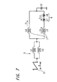
- Figure 7 shows an overall circuit diagram of the deflection apparatus having the above described structure.
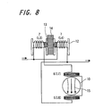
- Figure 8 shows the structure of the adjustment coil 7.
- Like parts in Figures 6 to 8 corresponding to those in Figures 1 to 5 are denoted by like reference numerals to omit repeated descriptions.
- the adjustment coil 7 in this example is comprised of coils L 3 and L 4 connected in parallel to each other as shown in Figure 7.
- the horizontal deflection coil 5 has coils L 1 and L 2 connected in parallel.
- the landing correction coil 6 has coils L 7 and L 8 connected in series with each other. Thus, an induced current I 7 ⁇ 8 will flow in the landing correction coil 6.
- the adjustment coil 7 is connected in series with the horizontal deflection coil 5.
- One end of the coil L 7 of the landing correction coil 6 is connected in series with the coil L 3 .
- the coil L 4 and the coil L 8 are connected to each other and further connected to one end of a capacitor C 1 the other end of which is grounded.
- the landing correction coil 6 is connected in parallel to the coil L 4 of the adjustment coil 7.
- the coils L 3 and L 4 of the adjustment coil 7 are wound around the coil bobbin 12 as shown in Figure 8.
- a screw core 13 will move in the opposite directions by turning a knob 14.
- the current flowing in the landing correction coil 6 is a resultant current of the induced current I 7 ⁇ 8 and the branch current I 3 of the sawtooth current 11 for horizontal deflection.
- the balance of inductances of the coils L 3 and L 4 will change by moving the knob 14 in Figure 8.
- the induced current I 7 ⁇ 8 in the landing correction coil 6 depends on the coupling strength between the horizontal deflection coil 5 and the landing correction coil 6, i.e. an electromagnetic induction coefficient.
- the Figure 9C shows the induced current I 7 ⁇ 8 .
- the current flowing in the landing correction coil 6 is the resultant current of the current I 3 and the induced current I 7 ⁇ 8 .
- waveforms of Figure 9A and Figure 9C are synthesized.
- the current flowing in the landing correction coil 6 has a waveform as shown in Figure 9A and Figure 9C are synthesized. Therefore, the current flowing in the landing correction coil 6 has a waveform as shown in Figure 9D.
- the current flowing in the landing correction coil 6 has a waveform as shown in Figure 9E.
- the magnetic field generated by the landing correction coil 6 fitted on the neck portion affects the CRT in Figure 6. Because the magnetic field generated by the landing correction coil 6 is added to the magnetic field generated by the horizontal deflection coil 5, having the same direction as that of the former magnetic field, the central position of the whole magnetic field distribution of the deflection apparatus 1 will move toward the neck portion 10 as shown by an arrow C in Figure 6. The moving of the center CL of the magnetic field toward the neck portion 10 as shown by an arrow C in Figure 6 brings the same effect that if the whole deflection yoke 2 moves mechanically toward the neck portion 10.
- the amplitude of the sawtooth current of the horizontal deflection cycle made to flow in the landing correction coil can be adjusted by the adjustment coil and the varying means.
Landscapes
- Physics & Mathematics (AREA)
- Electromagnetism (AREA)
- Engineering & Computer Science (AREA)
- Multimedia (AREA)
- Signal Processing (AREA)
- Video Image Reproduction Devices For Color Tv Systems (AREA)
Abstract
Description
Claims (10)
- A deflection apparatus characterized by comprising:a landing correction coil (6) provided near a horizontal deflection coil (5) of a deflection yoke (2) to generate a magnetic field (15) perpendicular to the axial direction of a neck portion (10) of a CRT (8);an adjustment coil (7) connected in series with the horizontal deflection coil (5) to make a sawtooth current synchronized with a horizontal deflection cycle flow in the landing correction coil (6) ; anda varying means (14) for varying the horizontal sawtooth current made to flow in the landing correction coil (6).
- A deflection apparatus according to claim 1, characterized in thatthe adjustment coil (7) is connected so as to form a bridge circuit; andthe landing correction coil (6) comprised of first and second coils (L7, L8) is connected between balance positions of the adjustment coil (7) forming the bridge circuit.
- A deflection apparatus according to claim 1,characterized in that
the adjustment coil (7) has first and second coils connected in parallel with each other, and to either of the first and second coils there is connected the first and second coils of the landing correction coil (6). - A deflection apparatus according to any one of claims 1 to 3, characterized in that
the landing adjustment coil (7) is wound in symmetrical positions on a coil bobbin and has an adjustment knob (14) for enabling a magnetic core arranged at the middle of the coil bobbin to be moved in and out of the symmetrically wound landing adjustment coil (7). - A deflection apparatus according to any one of claims I to 4, characterized in that
the adjustment coil (7) is comprised of at least two coils which are differentially changed by moving the magnetic core. - A deflection apparatus according to any one of claims 1 to 5, characterized in that
the landing correction coil (6) is arranged in the rear of the horizontal deflection coil (5) of the deflection yoke (2). - A deflection apparatus according to any one of claims 1 to 5, characterized in that
the landing correction coil (6) is provided within a magnetic field of the horizontal deflection coil (5) of the deflection yoke (2). - A CRT apparatus having a deflection yoke which is fitted onto a neck portion (10) of a CRT (8) and installed at a position where the yoke is pressed toward a funnel portion (9), characterized by comprising:a landing correction coil (6) provided at the rear of a horizontal deflection coil (5) of the deflection yoke (2) to generate a magnetic field perpendicular to the axial direction of the neck portion (10);an adjustment coil (7) connected in series with the horizontal deflection coil (5) to make a sawtooth current of a horizontal deflection cycle flow in the landing correction coil (6); anda varying means (14) for varying the sawtooth current of the horizontal deflection cycle made to flow in the landing correction coil (6).
- A CRT apparatus having a deflection yoke which is fitted onto a neck portion (10) of a CRT (8) and installed at a position where the yoke is pressed toward a funnel portion (9), characterized by comprising:a landing correction coil (6) provided within a magnetic field of a horizontal deflection coil (5) of the deflection yoke (2) to generate a magnetic field (15) perpendicular to the axial direction of the neck portion (10);an adjustment coil (7) connected in series with the horizontal deflection coil (5) to make a sawtooth current of a horizontal deflection cycle in the landing correction coil (6); anda varying means (14) for varying the sawtooth current of the horizontal deflection cycle flow made to flow in the landing correction coil (6).
- A beam landing adjustment method for adjusting electrically a deflection center position of a deflection yoke (2) which is installed in a CRT (8) and fixed at a certain point, characterized by comprising the steps of:generating a magnetic field (15) perpendicular to the axial direction of a neck portion (10) of the CRT (8) by providing a landing correction coil (6) within a magnetic field of a horizontal deflection coil (5) of the deflection yoke (2) or at the rear of the horizontal deflection coil (5);making a sawtooth current of a horizontal deflection cycle flow in the landing correction coil (6) through the horizontal deflection coil (5) and an adjustment; andadjusting the beam landing by varying the sawtooth current of the horizontal deflection cycle made to flow in the landing correction coil (6) using the adjustment coil (7) to move electrically the deflection center of the deflection yoke (2) in the back and forth direction of the neck portion (10).
Applications Claiming Priority (2)
| Application Number | Priority Date | Filing Date | Title |
|---|---|---|---|
| JP2000063893A JP2001256904A (en) | 2000-03-08 | 2000-03-08 | Deflection device, cathode ray tube device, and beam landing adjustment method |
| JP2000063893 | 2000-03-08 |
Publications (2)
| Publication Number | Publication Date |
|---|---|
| EP1132939A2 true EP1132939A2 (en) | 2001-09-12 |
| EP1132939A3 EP1132939A3 (en) | 2003-03-26 |
Family
ID=18583683
Family Applications (1)
| Application Number | Title | Priority Date | Filing Date |
|---|---|---|---|
| EP01400611A Withdrawn EP1132939A3 (en) | 2000-03-08 | 2001-03-08 | Deflection apparatus for a cathode ray tube, and beam landing adjustment method |
Country Status (4)
| Country | Link |
|---|---|
| US (1) | US6476569B2 (en) |
| EP (1) | EP1132939A3 (en) |
| JP (1) | JP2001256904A (en) |
| KR (1) | KR20010089189A (en) |
Families Citing this family (1)
| Publication number | Priority date | Publication date | Assignee | Title |
|---|---|---|---|---|
| JP2003223855A (en) | 2001-11-22 | 2003-08-08 | Hitachi Ltd | Deflection yoke and cathode ray tube device |
Family Cites Families (14)
| Publication number | Priority date | Publication date | Assignee | Title |
|---|---|---|---|---|
| JPS5271117A (en) | 1975-12-10 | 1977-06-14 | Mitsubishi Electric Corp | Bias device |
| EP0311806B1 (en) * | 1987-09-16 | 1994-02-16 | Kabushiki Kaisha Toshiba | Deflection unit for a colour cathode ray apparatus |
| JPH0355747A (en) * | 1989-07-24 | 1991-03-11 | Mitsubishi Electric Corp | Deflection yoke |
| ATE154468T1 (en) * | 1989-10-31 | 1997-06-15 | Thomson Tubes & Displays | DISPLAY DEVICE HAVING A COLOR IMAGE TUBE |
| JPH0433238A (en) * | 1990-05-29 | 1992-02-04 | Toshiba Corp | Color picture tube device |
| US5028850A (en) * | 1990-07-19 | 1991-07-02 | Rca Licensing Corporation | Deflection system with a controlled beam spot |
| JPH0576018A (en) | 1991-09-11 | 1993-03-26 | Toshiba Corp | Beam landing correcting device |
| JP3334378B2 (en) * | 1994-10-31 | 2002-10-15 | ソニー株式会社 | Deflection yoke |
| JP3399706B2 (en) * | 1995-08-09 | 2003-04-21 | エヌイーシー三菱電機ビジュアルシステムズ株式会社 | Color cathode ray tube display device and color purity adjusting method thereof |
| DE69618564T2 (en) * | 1995-08-29 | 2002-09-05 | Koninklijke Philips Electronics N.V., Eindhoven | COLOR DISPLAY DEVICE WITH ARRANGEMENT FOR CORRECTING LANDING ERRORS |
| JPH09199058A (en) * | 1996-01-23 | 1997-07-31 | Sony Corp | Balance coil |
| JPH1198520A (en) * | 1997-09-17 | 1999-04-09 | Sony Corp | Convergence correction circuit |
| TW445484B (en) * | 1998-07-14 | 2001-07-11 | Samsung Electronics Co Ltd | Linearity correction coil device and video display apparatus using the same |
| JP2000048739A (en) * | 1998-07-31 | 2000-02-18 | Sony Corp | Deflection yoke |
-
2000
- 2000-03-08 JP JP2000063893A patent/JP2001256904A/en active Pending
-
2001
- 2001-03-02 US US09/796,489 patent/US6476569B2/en not_active Expired - Fee Related
- 2001-03-07 KR KR1020010011762A patent/KR20010089189A/en not_active Withdrawn
- 2001-03-08 EP EP01400611A patent/EP1132939A3/en not_active Withdrawn
Also Published As
| Publication number | Publication date |
|---|---|
| KR20010089189A (en) | 2001-09-29 |
| EP1132939A3 (en) | 2003-03-26 |
| JP2001256904A (en) | 2001-09-21 |
| US20020047651A1 (en) | 2002-04-25 |
| US6476569B2 (en) | 2002-11-05 |
Similar Documents
| Publication | Publication Date | Title |
|---|---|---|
| US6215257B1 (en) | Apparatus for correcting misconvergence and geometric distortion of deflection yoke | |
| US4788470A (en) | Deflection yoke apparatus with compensation magnetic field generating means | |
| US6476569B2 (en) | Deflection apparatus, cathode ray tube apparatus and beam landing adjustment method | |
| US6573668B1 (en) | Color cathode ray tube having a convergence correction apparatus | |
| JPH0750935B2 (en) | Deflection-yoke device | |
| JP2001211460A (en) | Deflection yoke and color cathode ray tube receiver using the same | |
| KR100465295B1 (en) | Deflection Yoke for compensating Mis-convergence | |
| US6252359B1 (en) | Deflection apparatus | |
| JP2557854B2 (en) | Deflection device for color cathode ray tube | |
| KR200143631Y1 (en) | Convergence York Coil Unit of Deflection Yoke | |
| JPH06119884A (en) | Correcting coil for deflection yoke | |
| JP3153563B2 (en) | Deflection device for in-line type color picture tube | |
| JPH08190876A (en) | Color cathode-ray tube device | |
| JPH0727736Y2 (en) | In-line color picture tube image correction device | |
| JPH0721942A (en) | Improving method of magnetostriction characteristic of deflection yoke | |
| KR20020077564A (en) | circuit having balance coil and linearity coil on one holder in the deflection yoke for braun tube | |
| JPH11176358A (en) | Deflection yoke for in-line type color picture tube | |
| JP2002170504A (en) | Deflection yoke and display device | |
| JP2003061107A (en) | Apparatus for correcting mis-convergence and geometric distortion in deflection yoke using variable resistance | |
| JPH0389437A (en) | Deflection device for in-line type color picture tube | |
| JPH05328372A (en) | Deflection yoke | |
| JPH01151135A (en) | deflection yoke device | |
| JPH0482143A (en) | Deflecting device for color image-receiving tube | |
| KR19990021637U (en) | Distortion compensator of deflection yoke | |
| JPH0364839A (en) | Deflecting device for in-line color picture tube |
Legal Events
| Date | Code | Title | Description |
|---|---|---|---|
| PUAI | Public reference made under article 153(3) epc to a published international application that has entered the european phase |
Free format text: ORIGINAL CODE: 0009012 |
|
| AK | Designated contracting states |
Kind code of ref document: A2 Designated state(s): AT BE CH CY DE DK ES FI FR GB GR IE IT LI LU MC NL PT SE TR |
|
| AX | Request for extension of the european patent |
Free format text: AL;LT;LV;MK;RO;SI |
|
| PUAL | Search report despatched |
Free format text: ORIGINAL CODE: 0009013 |
|
| AK | Designated contracting states |
Kind code of ref document: A3 Designated state(s): AT BE CH CY DE DK ES FI FR GB GR IE IT LI LU MC NL PT SE TR Designated state(s): AT BE CH CY DE DK ES FI FR GB GR IE IT LI LU MC NL PT SE TR |
|
| AX | Request for extension of the european patent |
Extension state: AL LT LV MK RO SI |
|
| AKX | Designation fees paid | ||
| REG | Reference to a national code |
Ref country code: DE Ref legal event code: 8566 |
|
| STAA | Information on the status of an ep patent application or granted ep patent |
Free format text: STATUS: THE APPLICATION IS DEEMED TO BE WITHDRAWN |
|
| 18D | Application deemed to be withdrawn |
Effective date: 20030927 |