EP1132879A2 - Optical intrusion detection system using mode coupling - Google Patents
Optical intrusion detection system using mode coupling Download PDFInfo
- Publication number
- EP1132879A2 EP1132879A2 EP01301813A EP01301813A EP1132879A2 EP 1132879 A2 EP1132879 A2 EP 1132879A2 EP 01301813 A EP01301813 A EP 01301813A EP 01301813 A EP01301813 A EP 01301813A EP 1132879 A2 EP1132879 A2 EP 1132879A2
- Authority
- EP
- European Patent Office
- Prior art keywords
- optical
- intrusion
- light
- detection system
- detectors
- Prior art date
- Legal status (The legal status is an assumption and is not a legal conclusion. Google has not performed a legal analysis and makes no representation as to the accuracy of the status listed.)
- Granted
Links
Images


Classifications
-
- G—PHYSICS
- G08—SIGNALLING
- G08B—SIGNALLING SYSTEMS, e.g. PERSONAL CALLING SYSTEMS; ORDER TELEGRAPHS; ALARM SYSTEMS
- G08B13/00—Burglar, theft or intruder alarms
- G08B13/18—Actuation by interference with heat, light, or radiation of shorter wavelength; Actuation by intruding sources of heat, light, or radiation of shorter wavelength
- G08B13/181—Actuation by interference with heat, light, or radiation of shorter wavelength; Actuation by intruding sources of heat, light, or radiation of shorter wavelength using active radiation detection systems
- G08B13/183—Actuation by interference with heat, light, or radiation of shorter wavelength; Actuation by intruding sources of heat, light, or radiation of shorter wavelength using active radiation detection systems by interruption of a radiation beam or barrier
- G08B13/186—Actuation by interference with heat, light, or radiation of shorter wavelength; Actuation by intruding sources of heat, light, or radiation of shorter wavelength using active radiation detection systems by interruption of a radiation beam or barrier using light guides, e.g. optical fibres
-
- G—PHYSICS
- G08—SIGNALLING
- G08B—SIGNALLING SYSTEMS, e.g. PERSONAL CALLING SYSTEMS; ORDER TELEGRAPHS; ALARM SYSTEMS
- G08B13/00—Burglar, theft or intruder alarms
- G08B13/18—Actuation by interference with heat, light, or radiation of shorter wavelength; Actuation by intruding sources of heat, light, or radiation of shorter wavelength
- G08B13/181—Actuation by interference with heat, light, or radiation of shorter wavelength; Actuation by intruding sources of heat, light, or radiation of shorter wavelength using active radiation detection systems
- G08B13/183—Actuation by interference with heat, light, or radiation of shorter wavelength; Actuation by intruding sources of heat, light, or radiation of shorter wavelength using active radiation detection systems by interruption of a radiation beam or barrier
Definitions
- the present invention relates to an optical intrusion detection system using mode coupling, and more particularly, to an optical intrusion detection system using mode coupling in a multi-mode optical fiber.
- Optical intrusion detection systems which are to detect intrusion using optical fiber, are installed in the security area or restricted area of military units, airports, power plants and the like to protect their facilities from intruders. These systems can reduce the number of security guards and provide means for stable communications through a built-in optical fiber.
- the following three representative techniques are currently used in products: a method of measuring a change in a dynamic component of an optical signal using optical speckles; a method of measuring a static change in optical loss; and a method of measuring a change using optical time domain reflectometry (OTDR).
- OTDR optical time domain reflectometry
- a system for detecting intrusion using optical speckles determines intrusion or non-intrusion by blocking a part of light transmitted in a continuous wave form via a multi-mode optical fiber and measuring optical speckles or light power resulting from the interference of the remaining unblocked light.
- this system is sensitive to surrounding changes since it senses only a dynamic change component generated by intruders.
- An alternative optical intrusion detection technique is a method of detecting light loss caused when an optical fiber is bent or cut.
- this method is dull to dynamic changes such as shock waves and other physical disturbances of an optical fiber.
- Another alternative optical intrusion detection technique is a method using back scattering of an optical pulse.
- intrusion or non-intrusion is determined by detecting light which is scattered back by a light transmission medium while light is transmitted in a pulse form.
- This method has a feature in that even the position on an optical fiber where disturbance occurs can be detected.
- this method involves complicated signal processing, and has a higher false alarm rate than other techniques.
- an optical intrusion detection system including: a light source; an optical splitter for splitting light emitted from the light source and transmitted via an optical fiber; a plurality of detectors for detecting light power values split by the optical splitter; and a determiner for determining intrusion or non-intrusion by performing a predetermined operation on the output of each of the detectors.
- the invention provides an optical intrusion detection system for determining intrusion or non-intrusion by splitting light emitted from a light source and detecting and comparing the power of the split light.
- FIG. 1 is a block diagram of an optical intrusion detection system according to the present invention.
- an optical signal output from a laser diode which outputs a continuous wave is coupled to a multi-mode optical fiber, it travels in a multi-mode form because of the characteristics of the optical fiber.
- an intruder physically disturbs the multi-mode optical fiber through which the optical signal is traveling, light power transition occurs between the modes of light traveling within the optical fiber. If the modes of light travel into an optical splitter realized of multi-mode optical fibers, the power of each of the split beams of light output from the optical splitter differs from each of the others because each coupling coefficient of the modes differs in the optical splitter.
- the optical intrusion detection system can detect the physical disturbance by measuring changes in power of the split light at the output port.
- the optical intrusion detection system includes a light source 100, a multi-mode optical fiber 101 for transmitting light emitted from the light source 100, an optical splitter 102 for splitting light transmitted by the multi-mode optical fiber 101, first and second detectors 103 and 104 for detecting the powers of lights split by the optical splitter 102, and a determiner 105 for determining intrusion or non-intrusion using the detected powers of lights.
- the light source 100 is a laser diode for continuously outputting laser light.
- the optical intrusion detection system when laser light continuously output from the light source 100 is coupled to the multi-mode optical fiber 101, it proceeds in a multi-mode due to the characteristics of the multi-mode optical fiber 101. At this time, when an intruder physically disturbs the multi-mode optical fiber 101 through which light travels, each mode of the light is transited to another mode (that is, mode coupling occurs), light power split of each mode changes.
- mode coupling denotes power coupling between modes.
- the light power split of each mode is different for each mode since the modes within the optical splitter 102 have different coupling coefficients. Thus, the power of light split and output by the optical splitter 102 is changed.
- the first and second detectors 103 and 104 measure the power of light beams output from the optical splitter 102.
- the determiner 105 can determine the static and dynamic changes of light power by comparing the light power values detected and output from the first and second detectors 103 and 104 with each other through the subtraction and addition of the light power values.
- the optical splitter 102 is designed in consideration of the surrounding environment in order to selectively control the sensitivity to the surrounding environment.
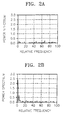
- FIGS. 2A and 2B are graphs showing power spectrums with respect to frequency in a normal state and an intrusion state, respectively. As shown in FIG. 2B, a power spectrum around a low frequency changes in the case that intrusion occurs.
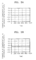
- FIGS. 3A and 3B are graphs showing an alternating current (AC) component varying due to the difference between the output signals of the first and second detectors of FIG. 1, with respect to time, in a normal state and in an intrusion state, respectively. As shown in FIG. 3B, a change occurs in an intrusion state rather than a normal state.
- AC alternating current
- FIGS. 4A and 4B are graphs showing a direct current (DC) component varying due to the sum of the output signals of the first and second detectors of FIG. 1, with respect to time, in a normal state and in an intrusion state, respectively. As shown in FIG. 4B, the DC component is smaller in an intrusion state than in a normal state.
- DC direct current
- an optical splitter can be designed in consideration of the external environment.
Landscapes
- Physics & Mathematics (AREA)
- General Physics & Mathematics (AREA)
- Burglar Alarm Systems (AREA)
- Geophysics And Detection Of Objects (AREA)
- Optical Communication System (AREA)
Abstract
Description
Claims (5)
- An optical intrusion detection system comprising:a light source (100);an optical splitter (102) for splitting light emitted from the light source and transmitted via an optical fiber (101);a plurality of detectors (103;104) for detecting light power values split by the optical splitter; anda determiner (105) for determining intrusion or non-intrusion by performing a predetermined operation on the output of each of the detectors.
- The optical intrusion detection system of claim 1, wherein the light source (100) is a laser diode that continuously outputs laser light.
- The optical intrusion detection system of claim 1 or 2, wherein the optical splitter (102) changes the power split between modes due to mode coupling which occurs within the multi-mode optical fiber (101), when the multi-mode optical fiber is disturbed.
- The optical intrusion detection system of claim 1, 2 or 3, wherein the determiner (105) determines intrusion or non-intrusion by extracting an alternating current (AC) component varying due to the difference between the output signals of the plurality of detectors.
- The optical intrusion detection system of claim 1, 2 or 3, wherein the determiner (105) determines intrusion or non-intrusion by extracting an AC component varying due to the difference between the output signals of the plurality of detectors and a direct current (DC) component varying due to the sum of the output signals thereof.
Applications Claiming Priority (2)
| Application Number | Priority Date | Filing Date | Title |
|---|---|---|---|
| KR2000010061 | 2000-02-29 | ||
| KR1020000010061A KR20010084777A (en) | 2000-02-29 | 2000-02-29 | Fiber optic intrusion system using mode coupling |
Publications (3)
| Publication Number | Publication Date |
|---|---|
| EP1132879A2 true EP1132879A2 (en) | 2001-09-12 |
| EP1132879A3 EP1132879A3 (en) | 2001-10-31 |
| EP1132879B1 EP1132879B1 (en) | 2006-04-19 |
Family
ID=36314058
Family Applications (1)
| Application Number | Title | Priority Date | Filing Date |
|---|---|---|---|
| EP01301813A Expired - Lifetime EP1132879B1 (en) | 2000-02-29 | 2001-02-28 | Optical intrusion detection system using mode coupling |
Country Status (6)
| Country | Link |
|---|---|
| US (1) | US20010024162A1 (en) |
| EP (1) | EP1132879B1 (en) |
| JP (1) | JP2001289960A (en) |
| KR (1) | KR20010084777A (en) |
| CN (1) | CN1311497A (en) |
| DE (1) | DE60118824T2 (en) |
Cited By (2)
| Publication number | Priority date | Publication date | Assignee | Title |
|---|---|---|---|---|
| CN104751585A (en) * | 2015-03-24 | 2015-07-01 | 中国电子科技集团公司第八研究所 | Fiber fence unit |
| RU2760513C1 (en) * | 2020-09-28 | 2021-11-25 | Акционерное Общество "Институт "Оргэнергострой" | Fence with a linear part with an interferometer with two arms |
Families Citing this family (10)
| Publication number | Priority date | Publication date | Assignee | Title |
|---|---|---|---|---|
| EP1649310A4 (en) * | 2003-07-18 | 2009-04-08 | Network Integrity Systems Inc | Multimode fiber optic intrusion detection system |
| US7142737B1 (en) * | 2005-01-12 | 2006-11-28 | Network Integrity Systems Inc. | Intrusion detection system for use on single mode optical fiber using a storage register for data |
| US8515278B2 (en) * | 2008-10-31 | 2013-08-20 | Futurewei Technologies, Inc. | Passive optical networks with mode coupling receivers |
| EP2396761A4 (en) * | 2008-11-14 | 2013-09-25 | Thinkeco Power Inc | System and method of democratizing power to create a meta-exchange |
| US20120177065A1 (en) * | 2011-01-09 | 2012-07-12 | Winzer Peter J | Secure Data Transmission Using Spatial Multiplexing |
| CN107153222A (en) * | 2017-04-28 | 2017-09-12 | 国网上海市电力公司 | A kind of communication platoon pore passage occupies passive on-line monitoring method |
| CN108469277A (en) * | 2018-04-28 | 2018-08-31 | 中国民航大学 | A kind of smart tags line apparatus based on airport security operational monitoring |
| CN110648481B (en) * | 2019-09-12 | 2022-02-15 | 深圳市矽赫科技有限公司 | Calibration method and perimeter alarm device |
| US11460634B2 (en) * | 2020-09-04 | 2022-10-04 | Marvell Asia Pte Ltd. | Method for detecting low-power optical signal with high sensitivity |
| RU2769906C2 (en) * | 2020-09-28 | 2022-04-08 | Акционерное Общество "Институт "Оргэнергострой" | Enclosure with linear part with combined interferometers |
Family Cites Families (3)
| Publication number | Priority date | Publication date | Assignee | Title |
|---|---|---|---|---|
| US5144689A (en) * | 1991-07-30 | 1992-09-01 | Fiber Sensys, Inc. | Multimode fiber sensor system with sensor fiber coupled to a detection fiber by spacer means |
| DE4332621A1 (en) * | 1993-09-24 | 1995-03-30 | Sicom Ges Fuer Sensor Und Vors | Measuring device for monitoring structures, terrain areas or the like |
| DE19713196C1 (en) * | 1997-03-28 | 1998-10-08 | Alv Laser Vertriebsgesellschaf | Fiber detector for a measuring device for determining light scattering |
-
2000
- 2000-02-29 KR KR1020000010061A patent/KR20010084777A/en not_active Ceased
-
2001
- 2001-02-27 JP JP2001051489A patent/JP2001289960A/en active Pending
- 2001-02-28 CN CN01108939A patent/CN1311497A/en active Pending
- 2001-02-28 EP EP01301813A patent/EP1132879B1/en not_active Expired - Lifetime
- 2001-02-28 DE DE60118824T patent/DE60118824T2/en not_active Expired - Fee Related
- 2001-02-28 US US09/794,097 patent/US20010024162A1/en not_active Abandoned
Cited By (2)
| Publication number | Priority date | Publication date | Assignee | Title |
|---|---|---|---|---|
| CN104751585A (en) * | 2015-03-24 | 2015-07-01 | 中国电子科技集团公司第八研究所 | Fiber fence unit |
| RU2760513C1 (en) * | 2020-09-28 | 2021-11-25 | Акционерное Общество "Институт "Оргэнергострой" | Fence with a linear part with an interferometer with two arms |
Also Published As
| Publication number | Publication date |
|---|---|
| JP2001289960A (en) | 2001-10-19 |
| EP1132879A3 (en) | 2001-10-31 |
| CN1311497A (en) | 2001-09-05 |
| DE60118824T2 (en) | 2006-11-30 |
| EP1132879B1 (en) | 2006-04-19 |
| US20010024162A1 (en) | 2001-09-27 |
| KR20010084777A (en) | 2001-09-06 |
| DE60118824D1 (en) | 2006-05-24 |
Similar Documents
| Publication | Publication Date | Title |
|---|---|---|
| US5194847A (en) | Apparatus and method for fiber optic intrusion sensing | |
| CN102292621B (en) | Improvements in Distributed Fiber Optic Sensing | |
| CA1316235C (en) | Methods of and systems for optical fiber sensing | |
| US8947232B2 (en) | Fault-tolerant distributed fiber optic intrusion detection | |
| KR101072747B1 (en) | An intrusion detection system for use on single mode optical fiber using a polarimeter | |
| US9891134B2 (en) | Long distance optical fiber sensing system and method | |
| EP1132879B1 (en) | Optical intrusion detection system using mode coupling | |
| US20080297772A1 (en) | Detecting a Disturbance in the Propagation of Light in an Optical Waveguide | |
| CN102197284A (en) | Fibre optic acoustic sensing | |
| CN104574742B (en) | An optical fiber perimeter security system based on Φ‑OTDR technology | |
| CA2471803A1 (en) | Method and apparatus using polarisation optical time domain reflectometry for security applications | |
| AU607605B2 (en) | Detection of stress applied to an optical fibre | |
| JP2000048269A (en) | Intrusion position detection device | |
| US5567933A (en) | Optical fiber detection system with disturbance and positive cut-loop detection capabilities | |
| EP0462197B1 (en) | A method of detecting and measuring external influence | |
| CN120313648B (en) | Fusion type optical fiber disturbance detection system and method based on multi-mode scattering | |
| FI103367B (en) | A way to detect the external effect of a fiber optic cable | |
| US12136328B2 (en) | Apparatus and method for detecting smoke based on polarization | |
| KR0163243B1 (en) | Invader alarm apparatus by using light fiber | |
| KR100363666B1 (en) | Fiber optic intrusion detection systems using an optical fiber net interwoven with a multiple of optical fibers | |
| KR100490909B1 (en) | Intrusion sensing and intrusion object discriminating method using an optical fiber | |
| WO2026083432A1 (en) | Fiber optic system for monitoring optical fibers and method thereof | |
| JPH0664157B2 (en) | Anomaly detection device using optical fiber | |
| CN113295259A (en) | Distributed optical fiber sensing system | |
| JPH03237313A (en) | Optical fiber distribution type physical quantity detector |
Legal Events
| Date | Code | Title | Description |
|---|---|---|---|
| PUAI | Public reference made under article 153(3) epc to a published international application that has entered the european phase |
Free format text: ORIGINAL CODE: 0009012 |
|
| AK | Designated contracting states |
Kind code of ref document: A2 Designated state(s): AT BE CH CY DE DK ES FI FR GB GR IE IT LI LU MC NL PT SE TR Kind code of ref document: A2 Designated state(s): DE FR GB |
|
| AX | Request for extension of the european patent |
Free format text: AL;LT;LV;MK;RO;SI |
|
| PUAL | Search report despatched |
Free format text: ORIGINAL CODE: 0009013 |
|
| AK | Designated contracting states |
Kind code of ref document: A3 Designated state(s): AT BE CH CY DE DK ES FI FR GB GR IE IT LI LU MC NL PT SE TR |
|
| AX | Request for extension of the european patent |
Free format text: AL;LT;LV;MK;RO;SI |
|
| RIC1 | Information provided on ipc code assigned before grant |
Free format text: 7G 08B 13/183 A, 7G 08B 13/186 B |
|
| 17P | Request for examination filed |
Effective date: 20020313 |
|
| AKX | Designation fees paid |
Free format text: DE FR GB |
|
| GRAP | Despatch of communication of intention to grant a patent |
Free format text: ORIGINAL CODE: EPIDOSNIGR1 |
|
| GRAS | Grant fee paid |
Free format text: ORIGINAL CODE: EPIDOSNIGR3 |
|
| GRAA | (expected) grant |
Free format text: ORIGINAL CODE: 0009210 |
|
| AK | Designated contracting states |
Kind code of ref document: B1 Designated state(s): DE FR GB |
|
| REG | Reference to a national code |
Ref country code: GB Ref legal event code: FG4D |
|
| REF | Corresponds to: |
Ref document number: 60118824 Country of ref document: DE Date of ref document: 20060524 Kind code of ref document: P |
|
| ET | Fr: translation filed | ||
| PLBE | No opposition filed within time limit |
Free format text: ORIGINAL CODE: 0009261 |
|
| STAA | Information on the status of an ep patent application or granted ep patent |
Free format text: STATUS: NO OPPOSITION FILED WITHIN TIME LIMIT |
|
| 26N | No opposition filed |
Effective date: 20070122 |
|
| PGFP | Annual fee paid to national office [announced via postgrant information from national office to epo] |
Ref country code: DE Payment date: 20090123 Year of fee payment: 9 |
|
| PGFP | Annual fee paid to national office [announced via postgrant information from national office to epo] |
Ref country code: GB Payment date: 20090225 Year of fee payment: 9 |
|
| PGFP | Annual fee paid to national office [announced via postgrant information from national office to epo] |
Ref country code: FR Payment date: 20090213 Year of fee payment: 9 |
|
| GBPC | Gb: european patent ceased through non-payment of renewal fee |
Effective date: 20100228 |
|
| REG | Reference to a national code |
Ref country code: FR Ref legal event code: ST Effective date: 20101029 |
|
| PG25 | Lapsed in a contracting state [announced via postgrant information from national office to epo] |
Ref country code: FR Free format text: LAPSE BECAUSE OF NON-PAYMENT OF DUE FEES Effective date: 20100301 |
|
| PG25 | Lapsed in a contracting state [announced via postgrant information from national office to epo] |
Ref country code: DE Free format text: LAPSE BECAUSE OF NON-PAYMENT OF DUE FEES Effective date: 20100901 |
|
| PG25 | Lapsed in a contracting state [announced via postgrant information from national office to epo] |
Ref country code: GB Free format text: LAPSE BECAUSE OF NON-PAYMENT OF DUE FEES Effective date: 20100228 |