BACKGROUND OF THE INVENTION
The present invention relates to a controller of a disk
array apparatus which stores data on multiple hard disk drives.
As compared with the computer main storage which is based
on the semiconductor memory, the disk subsystem (will be termed
simply "subsystem") which is based on the magnetic disk memory
is sluggish in regard to the I/O performance by a degree of the
order of 3-4 digits, and continuous efforts have been paid to
reduce the difference of these memories, i.e., improve the I/O
performance of the subsystem.
A known scheme to improve the I/O performance of the
subsystem is the adoption of a disk array system in which
multiple hard disk drives are organized to form a subsystem,
and data is stored on the multiple hard disk drives.
For example, a prior art system shown in Fig. 2 includes
multiple channel IF units 11 which implement the data transfer
between host computers 50 and disk array controllers 2, multiple
disk IF units 12 which implement the data transfer between
magnetic disk drives 5 and disk array controllers 2, cache memory
units 14 which temporarily store data of the hard disk drives
5, and shared memory units 13 which store control information
for the disk array controllers 2 (e.g., information on data
transfer control between the channel IF units 11 and disk IF
units 12 and the cache memory units 14 and control information
for data stored in the hard disk drives 5). In each disk array
controller 2, the shared memory unit 13 and cache memory unit
14 can be accessed by all channel IF units 11 and disk IF units
12.
In the disk array controller 2, the channel IF units 11
and disk IF units 12 are connected to the shared memory unit
13 by an interconnection 21, and the channel IF units 11 and
disk IF units 12 are connected to the cache memory unit 14 by
another interconnection 22.
The channel IF unit 11 has the interface for the connection
to host computers 50 and a microprocessor (not shown) which
controls the data transaction with the host computers 50. The
disk IF unit 12 has the interface for the connection to hard
disk drives 5 and a microprocessor (not shown) which controls
the data transaction with the hard disk drives 5. The disk IF
units 12 have the RAID function.
This conventional disk array controller 2 has an upper
limit of disk storage capacity which can be connected to it,
and therefore for storing data in excess of the volume of data
manageable by one disk array controller 2, multiple disk array
controllers 2 are installed and channels from the host computers
50 are connected to the disk array controllers 2. Furthermore,
for connecting host computers 50 in excess of the number of host
channels which can be connected to one disk array controller
2, multiple disk array controllers 2 are installed and connected
to the host computers 50 individually.
For data transfer between two disk array controllers 2,
channels from the host computers 50 are connected to the two
disk array controllers 2 and data is transferred via the host
computers 50.
Another prior art system shown in Fig. 3, which is
disclosed in U.S.Patent No.5,680,640, is designed for example
to transfer data between two disk array controllers 3 based on
the connection of part (two lines in Fig. 3) of the computer
interface paths of the disk array controllers 3 and the data
transfer from a hard disk drive 5 which is connected to one disk
array controller 3 to another hard disk drive 5 which is
connected to another disk array controller 3 through the data
transfer path 8.
Another prior art system shown in Fig. 4 is designed for
example to store data in excess of the volume of data manageable
by one disk array controller, connect host computers in excess
of the number of host channels which can be connected to one
disk array controller, or transfer data among multiple disk
array controllers, as shown in Fig. 4, based on the installation
of multiple disk array controllers 4 and the connection of their
computer interface paths to the host computers 50 via a
switch-based interconnection 23.
A disk array processing device disclosed in Japanese
Unexamined Patent Publication No.Hei-11-66693 includes two
director units which use a shared memory to recover data when
a data spindle which forms a disk array runs out of control.
This patent publication, however, does not show the installation
of multiple disk arrays.
In large business enterprises which typically include
banks, stock traders, and telephone companies, there are trends
of cutting the expenditure for the operation, maintenance and
management of computer systems and storage systems based on the
centralized installation of computers and storages which have
been installed distributively in many places. In this movement
with the times, large high-end disk array controllers are
required to bear the channel interface for the connection to
several-hundreds or more host computers and huge storage
capacities of several-hundreds terabytes or more.
At the same time, due to growing open markets in recent
years and storage area networks (SANs) which are expected to
prevail in coming years, there are rising demands of small-scale
(compact) disk array controllers which are comparable in
performance and reliability with large high-end disk array
controllers.
The former requirement will conceivably be met by
connecting multiple conventional large high-end disk array
controllers to build a huge disk array controller. The latter
requirement will conceivably be met by arranging a lowest-level
model (e.g., with small numbers of channel IF units and disk
IF units) of a conventional large high-end disk array controller.
An additional conceivable scheme is to connect a plurality of
this compact disk array controller thereby to build a controller
which supports systems of medium to large scales which have been
supported by a conventional disk array controller.
Accordingly, it becomes necessary for disk array
controllers to have the scalability so as to be constructed to
cover the range from a small to huge-scale controllers based
on the same basic architecture of high performance and high
reliability, and therefore there arises a demand of a disk array
controller, a plurality of which are integrated to operate as
a single disk array controller.
However, although the prior art system shown in Fig. 2
can have an increased number of channels and increased storage
capability for the host computers 50 by simply increasing the
number of disk array controllers 2, the host computers 50 need
to connect channels to all disk array controllers 2 so that one
host computer 50 can transact data with multiple disk array
controllers 2. Moreover, it is necessary for one host computer
50 which is going to make access to data to identify a disk array
controller 2 that is connected to the hard disk drive 5 which
stores the data. On this account, it is difficult to operate
multiple disk array controllers as a single disk array
controller.
The prior art system shown in Fig. 3 has disk array
controllers 3 interconnected by the data transfer path 8,
enabling one host computer 50 which is connected to a certain
disk array controller 3 to make access to data on a hard disk
drive 5 which is connected to other disk array controller 3,
and accordingly it is possible to operate multiple disk array
controllers 3 as a single disk array controller.
However, in case a host computer 50 issues a data read
request to a disk array controller 3 and the data is absent on
the hard disk drives 5 connected to the controller 3, it is
necessary for the disk array controller 3 to send the read
request to other disk array controller 3 over the data transfer
path 8, receive the requested data over the data transfer path
8 from the disk array controller 3 which is connected to the
hard disk drive 5 on which the data is stored, and send the
requested data to the host computer 50. On this account, this
system suffers a degraded performance when a host computer 50
makes access to data which is stored on a hard disk drive 5
connected to a disk array controller 3 other than the disk array
controller 3 connected to itself.
For coping with this matter, if a host computer 50
transfers in advance data of frequent access, which is stored
on a hard disk drive of a disk array controller other than that
connected to itself, to the hard disk drive 5 of the disk array
controller connected to itself, the system also suffers a
degraded performance due to the data transfer over the data
transfer path 8.
In the prior art system shown in Fig. 4, each host computer
50 can access to all disk array controllers 4 via the
switch-based interconnection 23. However, in order to
operate multiple disk array controllers 4 as a single disk array
controller, each switch of the interconnection 23 must have a
map indicating as to which of all disk array controllers 4
connected to the switch stores data, and must have a function
of analyzing the access request from a host computer 50 and
designating a disk array controller 4 which stores the requested
data.
Due to the need of request command analysis by the switches
besides the command analysis by the conventional channel IF
units 11, this system suffers a degraded performance in contrast
to the direct connection of the host computers 50 to the disk
array controllers 4.
The high-end disk array controllers have following
functions.
As a specific operational function, a data set
(corresponding to a logical volume) for one work is duplicated
and stored and both the original and duplicate data sets are
updated simultaneously in the ordinary work. At the emergence
of the need of backup for the data set for example, updating
of the duplicate data set is suspended and it is used for the
backup, while the original data set is used continuously for
the work, and the original and duplicate data sets are rendered
the matching process on completion of backup.
For accomplishing this operational function, with
duplicate data sets being held in different disk array
controllers, the prior art systems shown in Fig. 2 to Fig. 4
all need to transfer data sets among the disk array controllers,
resulting in a significantly deteriorated system performance.
SUMMARY OF THE INVENTION
An object of the present invention is to provide a disk
array controller having the scalability so as to be constructed
to cover the range from a small to huge-scale controllers based
on the same basic architecture of high performance and high
reliability.
More specifically, the present invention is intended to
provide a disk array system which is capable of alleviating the
deterioration of performance caused by the data transfer among
multiple disk array controllers which are designed to operated
as a single disk array controller, and accomplish the function
of a disk array controller based on a plurality of disk array
controllers while alleviating the deterioration of
performance.
In order to achieve the above objectives, the present
invention resides in a disk array controller which includes a
plurality of disk array control units, each having one or more
channel interface units for interfacing with a computer, one
or more disk interface units for interfacing with disk drives,
a cache memory unit which is connected to the channel interface
unit and disk interface unit and adapted to store temporarily
data which is written to or read out of the disk drives, and
a shared memory unit which is connected to the channel interface
unit and disk interface unit and adapted to store control
information of data transfer between the channel interface unit
and disk interface unit and the cache memory unit and control
information for the disk drives, and having a disk control
function for implementing the data read/write operation in
response to a data read/write request from the host computer
by operating on the channel interface unit to transfer data
between the interface with the host computer and the cache memory
unit and operating on the disk interface unit to transfer data
between the disk drive and the cache memory unit, and further
includes means of interconnecting the shared memory units in
the disk array control units and means of interconnecting the
cache memory units in the disk array control units, thereby
enabling the data read/write access from a channel interface
unit or disk interface unit in one disk array control unit to
a shared memory unit or cache memory unit in other disk array
control unit.
BRIEF DESCRIPTION OF THE DRAWINGS
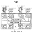
Fig. 1 is a block diagram showing the arrangement of a
disk array controller based on this invention;
Fig. 2 is a block diagram showing the arrangement of a
conventional disk array controller;
Fig. 3 is a block diagram showing the arrangement of
another conventional disk array controller;
Fig. 4 is a block diagram showing the arrangement of still
another conventional disk array controller;
Fig. 5 is a block diagram showing the arrangement of
another disk array controller based on this invention;
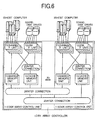
Fig. 6 is a block diagram showing the arrangement of still
another disk array controller based on this invention;
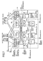
Fig. 7 is a block diagram showing the detailed arrangement
of the disk array control unit shown in Fig. 1;
Fig. 8 is a block diagram showing the arrangement of a
disk array controller made up of two disk array control units
shown in Fig. 7 connected together;
Fig. 9 is a block diagram showing the detailed arrangement
of the disk array control unit shown in Fig. 5;
Fig. 10 is a block diagram showing the arrangement of a
disk array controller made up of two disk array control units
shown in Fig. 9 connected together;
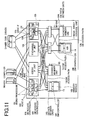
Fig. 11 is a block diagram showing the detailed
arrangement of the disk array control unit shown in Fig. 6;
Fig. 12 is a block diagram showing the arrangement a disk
array controller made up of two disk array control units shown
in Fig. 11 connected together;
Fig. 13 is a block diagram showing the arrangement of a
disk array controller made up of three disk array control units
shown in Fig. 7 connected together;
Fig. 14 is a perspective view showing the structure of
a disk array control unit built on a rack based on this invention;
Fig. 15 is a perspective view showing the structure of
a disk array controller made up of two disk array control units
which are built on racks and interconnected;
Fig. 16 is a perspective view showing the structure of
a disk array control unit built on a different rack based on
this invention;
Fig. 17 is a perspective view showing the structure of
a disk array controller made up of four disk array control units
which are built on one rack based on this invention;
Fig. 18 is a block diagram showing the wiring scheme for
three disk array control units based on inter-rack switches;
Fig. 19 is a perspective view of the structure of the
wiring shown in Fig. 18 based on this invention;
Fig. 20 is a block diagram showing the connection of three
disk array control units based on this invention;
Fig. 21 is a diagram showing an example of the data format
of information of path switching which is given to the switch
box; and
Fig. 22 is a table showing an example of the reference
table of information of path switching provided in the switch
box.
DESCRIPTION OF THE PREFERRED EMBODIMENTS
In the following embodiments of this invention, hard disk
drives are adopted for a large-capacity data storage. However,
it is not confined in this invention to hard disk drives, but
it can be DVDs for example.
As a preferred embodiment of this invention, the channel
interface units and disk interface units and the cache memory
units in the multiple disk array control units are
interconnected by a switch-based interconnection which extends
across the border of disk array control units, and the channel
interface units and disk interface units and the shared memory
units are interconnected by another switch-based
interconnection which extends across the border of disk array
control units.
As another preferred embodiment, the channel interface
units and disk interface units and the cache memory units in
the multiple disk array control units are interconnected by a
switch-based interconnection which extends across the border
of disk array control units, and the channel interface units
and disk interface units and the shared memory units are
connected directly for the portion within each disk array
control unit and interconnected for the portion between the
shared memory units between the disk array control units by a
switch-based interconnection which extends across the border
of disk array control units.
As another preferred embodiment, the channel interface
units and disk interface units and the cache memory units in
the multiple disk array control units are connected directly
for the portion within each disk array control unit and
interconnected for the portion between the cache memory units
between the disk array control units by a switch-based
interconnection which extends across the border of disk array
control units, and the channel interface units and disk
interface units and the shared memory units are connected
directly for the portion within each disk array control unit
and interconnected for the portion between shared memory units
between the disk array control units by a switch-based
interconnection which extends across the border of disk array
control units.
With respect to the data read/write operation between host
computers and the hard disk drives, the inventive disk array
controller includes a plurality of disk array control units,
each having channel interface units for interfacing with the
computers, disk interface units for interfacing with the hard
disk drives, a cache memory unit for storing temporarily data
which is written to or read out of the hard disk drives, a shared
memory unit for storing control information of data transfer
between the channel interface units and disk interface units
and the cache memory unit and control information for the hard
disk drives, means of connecting the channel interface units
and disk interface units to the cache memory unit, and means
of connecting the channel interface units and disk interface
units to the shared memory unit, and implementing data
read/write in response to a data read/write request from the
host computer by operating on the channel interface units to
transfer data between the interface with the host computer and
the cache memory unit and operating on the disk interface units
to transfer data between the hard disk drive and the cache memory
unit, and further includes means of interconnecting the shared
memory units in the disk array control units and means of
interconnecting the cache memory units in the disk array control
units, thereby enabling the data read/write access from a host
computer which is connected only to one disk array control unit
to a hard disk drive which is connected only to other disk array
control unit by way of the interconnection means.
Other problems and schemes of solving the problems based
on the present invention will become apparent from the following
description of embodiments taken in conjunction with the
accompanying drawings.
Embodiments of the present invention will be explained
with respect to the drawings.
[Embodiment 1]
Fig. 1, Fig. 7 and Fig. 8 show an embodiment of this
invention. Although devices of interconnection used in this
embodiment are based on switches, these devices which function
to transfer control information and data between two units may
otherwise be buses for example.
A disk array controller 1 of this embodiment is made up
of multiple disk array control units 1-1 as shown in Fig. 1.
Each disk array control unit 1-1 includes interface units
(channel IF units) 11 for interfacing with host computers 50,
interface units (disk IF units) 12 for interfacing with hard
disk drives 5, shared memory units 13, and cache memory units
14. The channel IF units 11 and disk IF units 12 and the shared
memory units 13 are connected by an interconnection 210 which
is shared by the disk array control units 1-1, and the channel
IF units 11 and disk IF units 12 and the cache memory units 14
are connected by another interconnection 220 which is shared
by the disk array control units 1-1. Accordingly, all channel
IF units 11 and disk IF units 12 can access to all shared memory
units 13 or all cache memory units 14 via the interconnection
210 or 220.
One disk array control unit, which may be either built
on a rack or built as a module, can operate as a stand-alone
disk array controller. Each disk array control unit is assumed
to be built on an individual rack in the explanation of Fig.
7.
Fig. 7 shows a specific internal arrangement of the disk
array control unit 1-1.
The disk array control unit 1-1 includes two channel IF
units 11 for interfacing with host computers 50, two disk IF
units 12 for interfacing with the hard disk drives 5, two shared
memory path switches (SM-SWs) 110, two cache memory path
switches (CM-SWs) 111, two shared memory units 13, two cache
memory units 14, shared memory (SM) access paths 135 and 136,
cache memory (CM) access paths 137 and 138, inter-unit SM paths
141, and inter-unit CM paths 142. The inter-unit SM paths and
inter-unit CM paths connect between the disk array control
units.
The channel IF unit 11 includes two host IFs 102 for
interfacing with the host computers 50, two microprocessors 101
which control the data transaction with the host computers 50,
an SM access controller 104 which controls the access to the
shared memory units 13, and a CM access controller 105 which
controls the access to the cache memory units 14. It implements
the data transfer between the host computers 50 and the cache
memory units 14 and the transfer of control information between
the microprocessors 101 and the shared memory units 13. The
microprocessors 101 and host IFs 102 are connected by an internal
bus 106. The CM access controller 105 is connected directly
to the two host Ifs 102. The SM access controller 104 is
connected directly to the two microprocessors 101.
The disk IF unit 12 includes two drive IFs 103 for
interfacing with hard disk drives 5, two microprocessors 101
which control the data transaction with the hard disk drives
5, an SM access controller 104 which controls the access to the
shared memory units 13, and a CM access controller 105 which
controls the access to the cache memory units 14. It implements
the data transfer between the hard disk drives 5 and the cache
memory units 14 and the transfer of control information between
the microprocessors 101 and the shared memory units 13. The
microprocessors 101 and drive IFs 103 are connected by an
internal bus 106, the CM access controller 105 is connected
directly to the drive IFs 103, and the SM access controller 104
is connected directly to the microprocessors 101. The disk IF
unit 12 also implement the RAID function.
The shared memory unit 13 includes a shared memory (SM)
controller 107 and a memory module 109, and it stores control
information of the disk array control unit 1-1 (e.g.,
information on data transfer control between the channel IF
units 11 and disk IF units 12 and the cache memory units 14,
and control information for data recorded on the hard disk drives
5).
The cache memory unit 14 includes a cache memory (CM)
controller 108 and a memory module 109, and it temporarily stores
data to be recorded on the hard disk drives 5.
The SM access controller 104 is connected to the two SM-SWs
110 which is different from each other by two SM access paths
135, and the SM-SWs 110 are connected to the two SM controllers
107 which is different from each other by two access paths 136.
Accordingly, each SM controller 107 has the connection of two
access paths 136 coming from the two SM-SWs 110, enabling each
SM controller 104 to have two access routes to each SM controller
107. In consequence, in the event of a fault on one access path
or in one SM-SW 110, the shared memory units 13 are kept
accessible through another route.
The CM access controller 105 is connected to the two CM-SWs
111 by two CM access paths 137, and the CM-SWs 111 are connected
to the two CM controllers 108 by two access paths 138.
Accordingly, each CM controller 108 has the connection of two
access paths 138 coming from the two CM-SWs 111, enabling each
CM controller 105 to have two access routes to each CM controller
108. In consequence, in the event of a fault on one access path
or in one CM-SW 111, the cache memory units 14 are kept accessible
through another route.
The SM-SW 110 has the connection of four SM access paths
135 coming from the two channel IF units 11 and two disk IF units
12, and also has the connection of two access paths 136 going
to the two shared memory units 13. The SM-SW 110 also has the
connection of two inter-unit SM paths 141 for the connection
with SM-SWs 110 of other disk array control unit 1-1. These
inter-unit SM paths 141 may be designed differently for input
and output, or may be designed equally for the bidirectional
information transfer.
The CM-SW 111 has the connection of four CM access paths
137 coming from the two channel IF units 11 and two disk IF units
12, and also has the connection of two access paths 138 going
to the two cache memory units 14. The CM-SW 111 also has the
connection of two inter-unit CM paths 142 for the connection
with CM-SWs 111 of other disk array control unit 1-1. These
inter-unit CM paths 142 have the same design as the inter-unit
SM paths 141.
Based on the above-mentioned access path connection of
the SM-SWs 110 and CM-SWs 111, these SWs 110 and 111 have a
function of directing access requests from the channel IF units
11 and disk IF units 12 over the four access paths to the two
access paths of the shared memory units 13 or cache memory units
14 within the self disk array control unit 1-1 and the two
inter-unit access paths of the shared memory units 13 or cache
memory units 14 of other disk array control unit 1-1.
In the arrangement of Fig. 7, the SM-SWs 110 are connection
nodes between the channel IF units 11 and disk IF units 12 and
the shared memory units 13, and the CM-SWs 111 are connection
nodes between the channel IF units 11 and disk IF units 12 and
the cache memory units 14.
Fig. 8 shows an example of the disk array controller 1
which is configured by connecting two disk array control units
1-1 shown in Fig. 7. The two disk array control units 1-1-1
and 1-1-2 have their SM-SWs 110 interconnected by inter-unit
SM paths 141 via inter-unit SM-SWs 121. Similarly, the CM-SWs
111 of the disk array control units 1-1-1 and 1-1-2 are
interconnected by inter-unit CM paths 142 via inter-unit CM-SWs
122. The SWs 121 and 122 are mounted as switch boxes.
In case, as in this embodiment, the disk array controller
is made up of two disk array control units 1-1, these units can
be connected directly through the inter-unit paths instead of
using the inter-unit SWs 121 and 122 without imposing any problem
on this invention, while eliminating the overhead process of
data transfer in the inter-unit SWs 121 and 122.
The disk array controller 1 shown in Fig. 8 will be able
to include three or more disk array control units 1-1 by
designing the inter-unit SWs 121 and 122 to have an increased
number of path connection. The number of the path, which can
be mounted to the inter-unit SWs 121 and 122, is physically
limited. For connecting disk array control units 1-1 in excess
of the limit in the number of path connection of the inter-unit
SWs 121 and 122, they cannot be connected by one inter-unit
SW. In the case, the inter-units SWs are used in multiple stages
to increase the number of the disk array controller connected.
Fig. 19 shows an example of a disk array controller which
is made up of three disk array control units built on individual
racks and interconnected through a switch box, as will be
explained in detail later.
For connecting three or more disk array control units 1-1,
the SM-SWs 110 and CM-SWs 111 in all units 1-1 are each connected
in a loop fashion as shown in Fig. 13. This interconnecting
scheme enables the loop connection of multiple disk array
control units 1-1 without using the inter-unit SWs 121 and 122.
Specifically, the inter-unit SM paths of adjacent units 1-1 and
the inter-unit CM paths of adjacent units 1-1 are each connected
by connectors. Preferably, these connectors of the inter-unit
SM paths 141 and inter-unit CM paths are fixed on the exterior
wall of the disk array control units 1-1 for the convenience
of the additional installation of units 1-1, although it is not
shown in the figure.
In the arrangement of Fig. 8, the SM-SWs 110, inter-unit
SM paths 141 and inter-unit SM-SWs 121 in unison constitute the
interconnection 210 shown in Fig. 1, and the CM-SWs 111,
inter-unit CM paths 142 and inter-unit CM-SWs 122 in unison
constitute the interconnection 220.
An example of the operation of the arrangement shown in
Fig. 8 for reading out data from a host computer 50 which is
connected to the disk array control unit 1-1-1 will be explained.
Initially, the host computer 50 issues a data read-out
request to the channel IF unit 11 in the disk array control unit
1-1-1 to which it is connected. The microprocessors 101 in the
channel IF unit 11 which has received the request makes access
to both shared memory units 13 in both disk array control units
1-1-1 and 1-1-2 thereby to find as to which hard disk drive 5
stores the requested data. The search is executed based on the
conversion table stored in the shared memory units 13 indicative
of the correspondence of the address of the requested data and
hard disk drives which stores the data.
Subsequently, the microprocessors 101 in the channel IF
unit 11 which has received the request makes access to both
shared memory units 13 in both disk array control units 1-1-1
and 1-1-2 thereby to find as to whether or not the requested
data is present in the cache memory units 14 in the disk array
control units 1-1-1 and 1-1-2. The search is based on
information stored in the shared memory units 13 indicative of
the directory of data of the cache memory units 14.
In one case of finding the requested data in the cache
memory unit 14 of the disk array control unit 1-1-1, the data
is transferred to the channel IF unit 11 via the CM-SW 111 within
the unit 1-1-1, and then it is sent to the host computer 50.
In other case of finding the data in the cache memory unit 14
of the disk array control unit 1-1-2, the data is transferred
to the channel IF unit 11 by way of the CM-SW 111 within the
unit 1-1-2, the inter-unit CM-SW 122 and the self CM-SW 111,
and then it is sent to the host computer 50.
In case the request data does not exist in any cache memory
unit 14, the microprocessor 101 issues a command to another
microprocessor 101 in the disk IF units 12 which is connected
with the hard disk drive 5 where the requested data is stored,
thereby operating it to read out and store the data from the
hard disk drive 5 into one cache memory unit 14. On receiving
the command, the microprocessor 101 in the disk IF unit 12 reads
the requested data out of the hard disk drive 5 and stores the
data in the cache memory unit 14 of the disk array control unit
1-1-1 or 1-1-2.
In one case of storing the data in the cache memory unit
14 in the disk array control unit 1-1-2 which is connected to
the hard disk drive 5 where the requested data is stored, the
data is transferred to the cache memory unit 14 via the CM-SW
111 in the disk array control unit 1-1-2. In another case
of storing the requested data in the cache memory unit 14 in
another disk array control unit 1-1-1 which is different from
the disk array control unit 1-1-2 connected with the hard disk
drives 5 in which the requested data is stored, the data is
transferred by way of the CM-SWs 111 of both units 1-1-2 and
1-1-1 and the inter-unit CM-SW 122.
After the requested data has been stored in the cache
memory unit 14, the microprocessor 101 in the disk IF unit 12
indicates the cache memory unit 14 where the data has been stored
to the command-issuing microprocessor 101 in the channel IF unit
11. In response to this indication, the microprocessor 101 in
the channel IF unit 11 read the data out of the cache memory
unit 14 where the data has been stored and sends it to the host
computer 50.
According to this embodiment, a host computer 50 can
transact data with a hard disk drive 5 by simply issuing an access
request to the disk array control unit 1-1 to which it is
connected without being concerned with as to which hard disk
drive 5 of which disk array control unit 1-1 is stored the data
in need. Namely, the host computer 50 can deal with the multiple
disk array control units 1-1 virtually as a single disk array
controller 1.
Furthermore, in the case of reading out data from a hard
disk drive 5 connected to a disk array control unit 1-1 which
is different from the unit 1-1 that has received the request,
the data can be read out by way of the internal interconnection
and cache memory unit 14, instead of moving the data through
the channel IF units 11 of both disk array control units 1-1,
whereby the deterioration of data read/write performance can
be alleviated.
[Embodiment 2]
Fig. 5, Fig. 9 and Fig. 10 show another embodiment of this
invention.
In Fig. 5, a disk array controller 1 which is made up of
multiple disk array control units 1-2 is arranged identically
to the preceding Embodiment 1 shown in Fig. 1 except for the
connection between the channel IF units 11 and disk IF units
12 and the shared memory units 13. In each disk array control
unit 1-2, the channel IF units 11 and disk IF units 12 and the
shared memory units 13 are connected directly. The shared
memory units 13 are interconnected via an interconnection 24
between the disk array control units 1-2. Connecting the
channel IF units 11 and disk IF units 12 and the shared memory
units 13 directly in each disk array control unit 1-2 reduces
the access time to the shared memory units 13 as compared with
the connection via the interconnection 210 which is the case
of Embodiment 1.
Fig. 9 shows a specific internal arrangement of the disk
array control unit 1-2. The internal arrangement of the disk
array control unit 1-2 is identical to the preceding Embodiment
1 shown in Fig. 7 except for the connection between the channel
IF units 11 and disk IF units 12 and the shared memory units
13.
The disk array control unit 1-2 includes two channel IF
units 11 for interfacing with computers 50, two disk IF units
12 for interfacing with hard disk drives 5, two cache memory
path switches (CM-SWs) 111, two shared memory units 13, two cache
memory units 14, shared memory (SM) access paths 139, a cache
memory (CM) access paths 137 and 138, inter-unit SM paths 143,
and inter-unit CM paths 142.
The SM access controller 104 is connected to two SM
controllers 107 which is different from each other by two SM
access paths 139. Accordingly, the SM controller 107 has the
connection of four SM access paths 139 coming from the two
channel IF units 11 and two disk IF units 12. The SM controller
107 also has the connection of two inter-unit SM paths 143 for
the connection with SM controllers 107 of other disk array
control unit 1-2.
Based on the above-mentioned access path connection of
the SM controller 107, it has a function of directing access
requests from the channel IF units 11 and disk IF units 12 over
the four access paths to the access paths of the memory modules
109 and the two inter-unit access paths 143 of the shared memory
units 13 in other disk array control unit 1-2.
Fig. 10 shows an example of the disk array controller 1
which is configured by connecting two disk array control units
1-2 shown in Fig. 9. The two disk array control units 1-2 have
their shared memory units 13 interconnected by inter-unit SM
paths 143 via inter-unit SM-SWs 121. The SM controllers 107
work for the connection nodes of the channel IF units and disk
IF units and the shared memory units. The remaining portion
is identical to the arrangement of Embodiment 1 shown in Fig.
8.
In case the disk array controller is made up of two disk
array control units 1-2, these units can be connected directly
through the inter-unit paths instead of using the inter-unit
SWs 121 and 122 without imposing any problem on this invention,
while eliminating the overhead process of data transfer in the
inter-unit SWs 121 and 122 to improve the performance, as in
the case of Embodiment 1.
The disk array controller 1 shown in Fig. 10 will be able
to include three or more disk array control units 1-2 by
designing the inter-unit SWs 121 and 122 to have an increased
number of path connection, as in the preceding Embodiment 1.
The number of the path, which can be mounted to the inter-unit
SWs 121 and 122, is physically limited. For connecting disk
array control units 1-2 in excess of the limit in the number
of path connection of the inter-unit SWs 121 and 122, they cannot
be connected by one inter-unit SW. In the case, the inter-units
SWs are used in multiple stages. These inter-unit SWs
are built in a switch box, as in the preceding Embodiment 1.
Three or more disk array control units 1-2 can be chained
in a loop fashion similar to the preceding Embodiment 1 shown
in Fig. 13. The plural disk array control units 1-2 can be
connected without using the inter-unit SWs 121 and 122.
The operation of the functional units in the disk array
control unit 1-2 for writing or reading out data to/from the
hard disk drives 5 by the host computers 50 is identical to the
preceding Embodiment 1 except that the access to the shared
memory unit 13 in other disk array control unit 1-2 takes place
via the shared memory unit 13 in the self unit 1-2 and the
interconnection 24.
The inter-unit SM paths 143, inter-unit SM-SWs 121, and
SM controller 107 in unison constitute the interconnection 24.
According to this embodiment, a host computer 50 can
transact data with a hard disk drive 5 by simply issuing an access
request to the disk array control unit 1-2 to which it is
connected without being concerned with as to which hard disk
drive 5 of which disk array control unit 1-2 is stored the data
in need. Namely, the host computer 50 can deal with the multiple
disk array control units 1-2 virtually as a single disk array
controller 1.
Furthermore, in the case of reading out data from a hard
disk drive 5 connected to a disk array control unit 1-2 which
is different from the unit 1-2 that has received the request,
the data can be read out by way of the internal interconnection
and cache memory unit 14, instead of moving the data through
the channel IF units 11 of both disk array control units 1-2,
whereby the deterioration of data read/write performance can
be alleviated.
[Embodiment 3]
Fig. 6, Fig. 11 and Fig. 12 show another embodiment of
this invention.
In Fig. 6, a disk array controller 1 which is made up of
multiple disk array control units 1-3 is arranged identically
to the preceding Embodiment 2 shown in Fig. 5 except for the
connection between the channel IF units 11 and disk IF units
12 and the cache memory units 14. In each disk array control
unit 1-3, the channel IF units 11 and disk IF units 12 and the
cache memory units 14 are connected by an interconnection 22.
The cache memory units 14 are interconnected between disk array
control units 1-3 by an interconnection 25. The channel IF
units 11 and disk IF units 12 and the shared memory units 13
are connected directly, whereas the channel IF units 11 and disk
IF units 12 and the cache memory units 14 are connected by the
interconnection 22, as in the case of the preceding Embodiment
2, by the following reason. The shared memory unit 13 deals
with control data having a size of several bytes for example,
whereas the cache memory unit 14 deals with data having a size
of several kilobytes for example. Therefore, it is intended
to raise the throughput based on the connection through the
interconnection 22 with a limited number of pins.
By the separate provision of the interconnection 22 which
connects the channel IF units 11 and disk IF units 12 and the
cache memory units 14 and the interconnection 25 which connects
the cache memory units 14 between the disk array control units
1-3, data transfer between cache memory units 14 of different
disk array control units 1-3 does not preclude the host computers
50 from making access to the cache memory units 14.
The disk IF unit implements the data transfer between
cache memories. The function of data transfer between cache
memory units 14 of different disk array control units 1-3 is
necessary for moving data to a disk array control unit of
less-frequent access in dealing with concentrated accesses from
host computers 50 to one disk array control unit 1-3.
Fig. 11 shows a specific internal arrangement of the disk
array control unit 1-3. The internal arrangement of the disk
array control unit 1-3 is identical to the preceding Embodiment
2 shown in Fig. 9 except for the connection between the channel
IF units 11 and disk IF units 12 and the cache memory units 14.
The CM controllers 108 work for the connection nodes of the
channel IF units, disk IF units and cache memory units.
The disk array control unit 1-3 includes two channel IF
units 11 for interfacing with host computers 50, two disk IF
units 12 for interfacing with hard disk drives 5, two cache
memory path switches (CM-SWs) 111, two shared memory units 13,
two cache memory units 14, shared memory (SM) access paths 139,
cache memory (CM) access paths 137 and 138, inter-unit SM paths
143, and inter-unit CM paths 144.
The CM access controller 105 is connected to two CM-SWs
111 by two CM access paths 137, and the CM-SW 111 is connected
to two CM controllers 108 by two access paths 138. Accordingly,
the CM controller 108 has the connection of two access paths
138 coming from the two CM-SWs 111, and it also has the connection
of two inter-unit CM paths 144 for the connection with CM
controllers 108 of other disk array control unit 1-3.
Based on the above-mentioned access path connection of
the CM controller 108, it has a function of directing access
requests from the CM-SWs 111 over the two CM access paths 138
to the access paths of the memory modules 109 and the two
inter-unit CM access paths 144 of the cache memory units 14 in
other disk array control unit 1-3.
The CM-SW 111 has the connection of four CM access paths
137 coming from the two channel IF units 11 and two disk IF units
12, and also has the connection of two access paths 138 going
to the two cache memory units 14.
Based on this access path connection of the CM-SW 111,
it has a function of directing access requests from the channel
IF units 11 and disk IF units 12 over the four CM access paths
137 to the two CM access paths 138 of the cache memory units
14.
Fig. 12 shows an example of the disk array controller 1
which is configured by connecting two disk array control units
1-3 shown in Fig. 11. The two disk array control units 1-3 have
their cache memory units 14 interconnected by inter-unit CM
paths 144 via inter-unit CM-SWs 122. The remaining portion is
identical to the arrangement of Embodiment 2 shown in Fig. 10.
In case the disk array controller is made up of two disk
array control units 1-3, these units can be connected directly
through the inter-unit paths instead of using the inter-unit
SWs 121 and 122 without imposing any problem on this invention,
while eliminating the overhead process of data transfer in the
inter-unit SWs 121 and 122 to improve the performance, as in
the case of Embodiment 2.
The disk array controller 1 shown in Fig. 12 will be able
to include three or more disk array control units 1-3 by
designing the inter-unit SWs to have an increased number of path
connection, as in the preceding Embodiment 2. The number of
the path, which can be mounted to the inter-unit SWs 121 and
122, is physically limited. For connecting disk array control
units 1-3 in excess of the limit in the number of path connection
of the inter-unit SWs 121 and 122, they cannot be connected by
one inter-unit SW. In the case, the inter-units SWs are used
in multiple stages.
Three or more disk array control units 1-3 can be chained
in a loop fashion similar to the preceding Embodiment 1 shown
in Fig. 13. The plural disk array control units 1-3 can be
connected without using the inter-unit SWs 121 and 122.
The operation of the functional units in the disk array
control unit 1-3 for transacting data with the hard disk drives
5 by the host computers 50 is identical to the preceding
Embodiment 2 except that the access to the cache memory unit
14 in other disk array control unit 1-3 takes place via the cache
memory unit 14 in the self unit 1-3 and the interconnection 25.
According to this embodiment, a host computer 50 can
transact data with a hard disk drive 5 by simply issuing an access
request to the disk array control unit 1-3 to which it is
connected without being concerned with as to which hard disk
drive 5 of which disk array control unit 1-3 is stored the data
in need. Namely, the host computer 50 can deal with the multiple
disk array control units 1-3 virtually as a single disk array
controller 1.
Furthermore, in the case of reading out data from a hard
disk drive 5 connected to a disk array control unit 1-3 which
is different from the unit 1-3 that has received the request,
the data can be read out by way of the internal interconnection
and cache memory unit 14, instead of moving the data through
the channel IF units 11 of both disk array control units 1-3,
whereby the deterioration of data read/write performance can
be alleviated.
Next, examples of the usage of the embodiments of this
invention will be explained.
High-end disk array controllers have the following
function. In the function, a data set (corresponding to a
logical volume) for one work is duplicated and stored, and both
the original and duplicate data sets are updated simultaneously
in the ordinary work. At the emergence of the need of backup
for the data set for example, updating of the duplicate data
set is suspended and it is used for the backup, while the original
data set is used continuously for the work, and the original
and duplicate data sets are rendered the matching process on
completion of backup.
In a disk array controller 1, which have been explained
as Embodiment 1, a method of accomplishing this function for
storing a duplicate data set in the different disk array control
units 1-1 will be explained with reference to Fig. 8. It is
assumed that an original data set is stored on the hard disk
drive 5 connected to the disk array control unit 1-1-1 and a
duplicate data set is stored on the hard disk drive 5 connected
to the disk array control unit 1-1-2 in Fig. 8. It is also
assumed that the host computer 50 connected to the disk array
control unit 1-1-1 works for the ordinary work and the host
computer 50 connected to the disk array control unit 1-1-2 works
to backup data on a tape storage unit (not shown) connected to
it.
In the ordinary work, in the event of a request of the
host computer 50, which is connected to the disk array control
unit 1-1-1, to write data to an intended data set, the
microprocessor 101 in the channel IF unit 11, which is connected
to the host computer 50 connected to the disk array control unit
1-1-1, transfers and writes the data which is sent from the host
computer 50 into the cache memory unit 14 of the disk array
control unit 1-1-1. Subsequently, the microprocessor 101
issues a command by way of the shared memory unit 13 of the disk
array control unit 1-1-1 to the microprocessor 101 in the disk
IF unit 12 which is connected to the hard disk drive 5 where
the original data set is stored, thereby operating on it to read
out data from the cache memory unit 14 of the disk array control
unit 1-1-1, transfers the data to the disk IF unit 12 which is
connected to the hard disk drive 5 where the original data set
is stored, and operates on the disk IF unit 12 to transfer and
write the data onto the hard disk drive 5.
The microprocessor 101 in the channel IF unit 11 of the
disk array control unit 1-1-1, which monitors the updating of
data of the original data set, stores in the shared memory units
13 of the disk array control unit 1-1-1 the control information
indicative of the quantity of updated data of the original data
set. When the quantity of updated data exceeds a predetermined
value, the microprocessor 101 issues a command to the
microprocessor 101 in the disk IF unit 12 which is connected
with the hard disk drive 5 where the original data set is stored,
thereby operating on it to revise the duplicate data set to match
with the updated content of the original data set.
The command receiving microprocessor 101 reads out the
updated data from the hard disk drive 5 and converts the
addresses of updated data into addresses of the duplicate data
set. It transfers and writes the updated data via the CM-SW
111 of the disk array control unit 1-1-1, inter-unit CM-SW 122
and CM-SW 111 of the disk array control unit 1-1-2 into the cache
memory unit 14 of the disk array control unit 1-1-2.
Subsequently, the microprocessor 101 reads out the
updated data from the cache memory unit 14, transfers the data
to the disk IF unit 12 which is connected to the hard disk drive
5 where the duplicate data set is stored, and the data is
transferred and stored onto the hard disk drive 5.
Based on the foregoing operation, the disk array
controller maintains the original data set and duplicate data
set during the ordinary work.
In the event of a request of the host computer 50, which
is connected to the disk array control unit 1-1-2, to backup
data for an intended data set, the microprocessor 101 in the
channel IF unit 11 connected to the host computer 50 issues a
command by way of the shared memory unit 13 of the disk array
control unit 1-1-1 to the microprocessor 101 in the channel IF
unit 11 which is connected to the host computer 50 having the
ordinary work, thereby operating on it to halt the updating of
the duplicate data set. The command receiving microprocessor
101 halts the updating of duplicate data set. The
microprocessor 101 in the channel IF unit 11, which is connected
to the backup requesting host computer 50, issue a command by
way of the shared memory unit 13 of the disk array control unit
1-1-2 to the microprocessor 101 in the disk IF unit 12 which
is connected to the hard disk drive 5 where the duplicate data
set is stored, thereby operating on it to read out and transfer
the duplicate data set from the hard disk drive 5 to the disk
IF unit 12, from which it is transferred and written into the
cache memory unit 14 of the disk array control unit 1-1-2.
Subsequently, the microprocessor 101 in the channel IF
unit 11 reads out the duplicate data set from the cache memory
unit 14 of the disk array control unit 1-1-2 and transfers it
to the channel IF unit 11, from which it is sent to the backup
requesting host computer 50.
On completion of backup of data set, the microprocessor
101 in the channel IF unit 11, which is connected to the backup
requesting host computer 50, issues a command to the
microprocessor 101 in the channel IF unit 11 which is connected
to the host computer 50 having the ordinary work through the
shared memory units 13 of the disk array control unit 1-1-1,
thereby operating on it to revise the duplicate data set to match
with the content of the original data set which has been updated
during the backup process. This operation is identical to the
data updating in the ordinary work explained previously.
In accomplishing the above-mentioned function, this
operational scheme enables the movement of data between the two
disk array control units 1-1-1 and 1-1-2 via the internal
interconnections and cache memory units 14, eliminating the need
of data transfer via the channel IF units of both disk array
control units 1-1-1 and 1-1-2, whereby the deterioration of
system performance during the implementation of this function
is alleviated and thus the deterioration of efficiency of the
user's ordinary work is prevented.
This operational scheme can be carried out equally in the
disk array controller 1 of Embodiment 2 and Embodiment 3 without
problems, and the same effectiveness is attained.
Other usages include the following.
In the disk array controllers 1 of Embodiment 1,
Embodiment 2 and Embodiment 3, when a host computer 50 sends
a data read request, for example, to a disk array control unit
and if the data is absent on the hard disk drive 5 connected
to the unit, it is necessary to read out the data via an
interconnection from another disk array control unit connected
with a hard disk drive 5 where the data is stored and send the
data to the requesting host computer 50. The data read/write
operation across the border of disk array control units, as in
this case, results in the deterioration of performance as
compared with the operation within a unit.
For avoiding the data transfer between units, it is
necessary for the system to have a function of moving data, which
is accessed frequently by one host computer 50 and is stored
on a hard disk drive connected to a disk array control unit other
than the control unit connected to the one host computer 50,
to the hard disk drive 5 of the control unit connected to the
one host computer 50.
This data moving function implemented by the disk array
controller 1 of Embodiment 1 will be explained with reference
to Fig. 8.
The microprocessor 101 in the channel IF unit 11 monitors
the frequency of access to data sets (corresponding to logical
volumes) on all hard disk drives 5, and stores control
information indicative of the access frequency of the data sets
in the shared memory units 13 within the same disk array control
unit 1-1-1.
If the host computer 50 connected to the disk array control
unit 1-1-1 makes access to the data set on the hard disk drive
5 connected to another disk array control unit 1-1-2 to
concentrate the access on the data set, the access frequency
is exceed a predetermined rate, the microprocessor 101 in the
channel IF unit 11 of the disk array control unit 1-1-1 issues
a command through the shared memory unit 13 in the other disk
array control unit 1-1-2 to the microprocessor 101 in the disk
IF unit 12 which is connected with the hard disk drive 5 where
the data set is stored, thereby operating on it to read out the
data set and transfer and write the data set into the cache memory
unit 14 of the disk array control unit 1-1-2.
Subsequently, the microprocessor 101 in the channel IF
unit 11 of the disk array control unit 1-1-1 reads out and
transfers the relevant data from the cache memory unit 14 of
the disk array control unit 1-1-2 to the cache memory unit 14
of the disk array control unit 1-1-1. The microprocessor 101
subsequently issues a command by way of the shared memory unit
13 in the disk array control unit 1-1-1 to the microprocessor
101 in the disk IF unit 12 of the disk array control unit 1-1-1,
thereby operating on it to read out, transfer and write the
relevant data from the cache memory unit 14 of the disk array
control unit 1-1-1 onto the hard disk drive 5.
This operational scheme enables the movement of data
between two disk array control units 1-1 via the internal
interconnections and cache memory units 14, eliminating the need
of data transfer via the channel IF units of both disk array
control units, whereby the deterioration of system performance
during the data movement is alleviated and thus the
deterioration of efficiency of the user's ordinary work is
prevented.
This operational scheme can be carried out equally in the
disk array controller 1 of Embodiment 2 and Embodiment 3 without
problems, and the same effectiveness is attained.
Next, the structure of the disk array controllers of
Embodiment 1, Embodiment 2 and Embodiment 3 will be explained.
Fig. 14 shows an example of the structure of the disk array
control unit 1-1 of Embodiment 1 shown in Fig. 7 built on a rack
201. The channel IF units 11 are arranged in channel IF packages
(PKs) 311, the disk IF units 12 are arranged in disk IF packages
312, the SM-SWs 110 and CM-SWs 111 are arranged in switch
packages 320, and the shared memory units 13 and cache memory
units 14 are arranged in memory packages 330. These packages
are plugged into the sockets on a back board 340, which has the
wiring of the SM access paths 135 and 136 and the CM access paths
137 and 138.
The switch packages 320 has the connection of cables of
the inter-unit SM paths 141 and cables of the inter-unit CM paths
142, and these cables have other ends connected to connectors
221 and 222, respectively, on the side wall of the rack 201.
The cables are not shown. A power unit 350 supplies electric
power to the packages. The disk array control unit built on
a rack as shown operates as a stand-alone disk array controller.
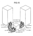
Fig. 15 shows an example of the interconnection of two
sets of the disk array control unit built on the rack 201 shown
in Fig. 14.
A switch box 210 houses the inter-unit SM-SWs 121 and
inter-unit CM-SWs 122 shown in Fig. 8. The inter-unit SM paths
141 coming from the inter-unit SM-SWs 121 are connected to
connectors 221, and the inter-unit CM paths 142 coming from the
inter-unit CM-SWs 122 are connected to connectors 222.
For interconnecting the two disk array control units on
the racks 201 and 202, the inter-unit SM path connectors 221
on the rack 201 are connected to the connectors 221 on the switch
box 210 with cables 231, and the inter-unit CM path connectors
222 on the rack 201 are connected to the connectors 222 on the
switch box 210 with cables 232. Similarly, the connectors 221
on the rack 202 are connected to the connectors 221 on the switch
box 210 with cables 231, and the inter-unit CM path connectors
222 on the rack 202 are connected to the connectors 222 on the
switch box 210 with cables 232.
The disk array controller built on two racks in this manner
can deal with an increased number of host computer channels and
an increased storage capability.
By designating the racks 201 and 202 to be a basic and
extension racks, respectively, and accommodating the switch box
210 inside the extension rack 202, it becomes possible to
eliminate the floor space for the switch box 210 without
increasing the manufacturing cost of the basic rack 201.
This structural scheme can also be applied to the disk
array controllers of Embodiment 2 and Embodiment 3 without any
problem.
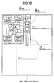
Fig. 18 shows the interconnection of three disk array
control units by inter-unit SM-SWs 121 and CM-SWs 122. Each
switch (SW) which connects three disk array control units must
have a larger capability as compared with the case of connecting
two units. Specifically, disk array control units 1-1-1,1-1-2
and 1-1-3 are interconnected through inter-unit SM paths
141 and inter-unit CM paths 142 via the inter-unit SM-SWs 121
and CM-SWs 122, and function as a disk array controller.
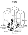
Fig. 19 shows the structure of this disk array controller.
The switch box 210 has a separate rack. The disk array control
units built on individual racks 201,202 and 203 are
interconnected by inter-unit SM path cables 231 and connectors
221 and inter-unit CM path cables 232 and connectors 222.
Providing more capability and more connectors for the switch
box 210 for connecting four or more disk array control units
facilitates the additional installation in the future.
Fig. 21 shows the format of data which is transferred
through the switch box 210. Data has a form of packet, and it
consists of a destination address field 401, command field 402
and data field 403. The address is of the shared memory and
cache memory.
Fig. 22 shows a reference table 410 for path switching
provided in the switch box 210. This table contains the
correspondence between the destination address and the port
number of the disk array control unit. The switch box 210 makes
reference to the path switching table to determine a destination
unit based on the address 401 in the packet data 400 and
implements the path switching.
Additional installation of disk array control units is
carried out based on the following procedure. If the switch
box 210 has spare connectors for additional disk array control
units, cables 231 and 232 are connected to these connectors.
If there are no spare connectors, another switch box is added
in a multi-stage configuration and cables 231 and 232 are
connected to it. The path switching table 410 in the switch
box 210 is revised to include the addresses and port numbers
for the additional disk array control units. An alternative
design of the table is to preset additional addresses with flags
so that address flags are turned on for the additional unit
installation.
Fig. 20 shows another unit interconnection scheme. In
a disk array controller, three disk array control units are
interconnected in series. SM-SWs 110 and CM-SWs 111 have a
bridge function of transferring incoming data intact to other
disk array control unit. These SM-SWs 110 and CM-SWs 111 may
be replaced with common buses, by which multiple disk array
control units are interconnected.
Further the other embodiment will be shown as follows.
As shown in Fig. 16, a disk array control unit made up
of a minimal number of packages (PKs), which are used in the
unit rack 201 shown in Fig. 14, is built on a rack 205.
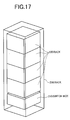
As shown in Fig. 17, two or more unit racks 205 and a switch
box 210 are built on a large rack 206, and the units on the racks
205 are interconnected via the switch box 210 based on the
interconnection scheme of the sixth embodiment. This structure
is suitable for middle-scale to large-scale disk array
controllers. The rack 205 has the same role for the disk array
control unit as of the foregoing one, or alternatively the disk
array control unit may have a module structure. Each disk array
control unit on the rack 206 may include an individual power
unit, or all units may be supplied with power from a single power
unit.
According to the present invention, it becomes possible
to construct a disk array system which is based on the operation
of multiple disk array control units as a single disk array
controller and is capable of alleviating the deterioration of
performance caused by the movement of data between the disk array
control units.