EP1132759A1 - Optical fiber - Google Patents
Optical fiber Download PDFInfo
- Publication number
- EP1132759A1 EP1132759A1 EP00944261A EP00944261A EP1132759A1 EP 1132759 A1 EP1132759 A1 EP 1132759A1 EP 00944261 A EP00944261 A EP 00944261A EP 00944261 A EP00944261 A EP 00944261A EP 1132759 A1 EP1132759 A1 EP 1132759A1
- Authority
- EP
- European Patent Office
- Prior art keywords
- optical fiber
- covering layer
- layer
- filler
- covering
- Prior art date
- Legal status (The legal status is an assumption and is not a legal conclusion. Google has not performed a legal analysis and makes no representation as to the accuracy of the status listed.)
- Withdrawn
Links
- 239000013307 optical fiber Substances 0.000 title claims abstract description 316
- 239000011521 glass Substances 0.000 claims abstract description 38
- 238000005253 cladding Methods 0.000 claims abstract description 36
- 239000011347 resin Substances 0.000 claims description 49
- 229920005989 resin Polymers 0.000 claims description 49
- 239000000945 filler Substances 0.000 claims description 40
- 238000000034 method Methods 0.000 claims description 26
- 239000012530 fluid Substances 0.000 claims description 24
- 239000007788 liquid Substances 0.000 claims description 21
- 239000007787 solid Substances 0.000 claims description 18
- 239000004925 Acrylic resin Substances 0.000 claims description 12
- 239000000463 material Substances 0.000 claims description 11
- 229920001296 polysiloxane Polymers 0.000 claims description 10
- 229920002545 silicone oil Polymers 0.000 claims description 10
- 230000035515 penetration Effects 0.000 claims description 7
- 239000003112 inhibitor Substances 0.000 claims description 5
- 238000009529 body temperature measurement Methods 0.000 claims description 2
- 230000002401 inhibitory effect Effects 0.000 claims 1
- 230000005540 biological transmission Effects 0.000 abstract description 55
- 238000005259 measurement Methods 0.000 abstract description 28
- 238000009864 tensile test Methods 0.000 abstract description 3
- 239000010410 layer Substances 0.000 description 167
- 239000006185 dispersion Substances 0.000 description 43
- 230000001419 dependent effect Effects 0.000 description 37
- 239000000835 fiber Substances 0.000 description 26
- 230000003287 optical effect Effects 0.000 description 19
- 238000000691 measurement method Methods 0.000 description 13
- 230000000994 depressogenic effect Effects 0.000 description 11
- 238000012360 testing method Methods 0.000 description 11
- 230000000694 effects Effects 0.000 description 9
- -1 isocyanate compound Chemical class 0.000 description 8
- 238000004804 winding Methods 0.000 description 8
- 238000005452 bending Methods 0.000 description 7
- 238000006073 displacement reaction Methods 0.000 description 7
- UHESRSKEBRADOO-UHFFFAOYSA-N ethyl carbamate;prop-2-enoic acid Chemical compound OC(=O)C=C.CCOC(N)=O UHESRSKEBRADOO-UHFFFAOYSA-N 0.000 description 7
- 235000019589 hardness Nutrition 0.000 description 7
- 239000012948 isocyanate Substances 0.000 description 7
- 238000009826 distribution Methods 0.000 description 6
- BASFCYQUMIYNBI-UHFFFAOYSA-N platinum Chemical compound [Pt] BASFCYQUMIYNBI-UHFFFAOYSA-N 0.000 description 5
- 239000000853 adhesive Substances 0.000 description 4
- 230000001070 adhesive effect Effects 0.000 description 4
- 238000004519 manufacturing process Methods 0.000 description 4
- 230000010287 polarization Effects 0.000 description 4
- 229910052691 Erbium Inorganic materials 0.000 description 3
- 229910000831 Steel Inorganic materials 0.000 description 3
- 239000003054 catalyst Substances 0.000 description 3
- 238000002474 experimental method Methods 0.000 description 3
- 229910052697 platinum Inorganic materials 0.000 description 3
- 239000002904 solvent Substances 0.000 description 3
- 239000010959 steel Substances 0.000 description 3
- CSCPPACGZOOCGX-UHFFFAOYSA-N Acetone Chemical compound CC(C)=O CSCPPACGZOOCGX-UHFFFAOYSA-N 0.000 description 2
- KAKZBPTYRLMSJV-UHFFFAOYSA-N Butadiene Chemical compound C=CC=C KAKZBPTYRLMSJV-UHFFFAOYSA-N 0.000 description 2
- LFQSCWFLJHTTHZ-UHFFFAOYSA-N Ethanol Chemical compound CCO LFQSCWFLJHTTHZ-UHFFFAOYSA-N 0.000 description 2
- 239000002390 adhesive tape Substances 0.000 description 2
- 229910052782 aluminium Inorganic materials 0.000 description 2
- XAGFODPZIPBFFR-UHFFFAOYSA-N aluminium Chemical compound [Al] XAGFODPZIPBFFR-UHFFFAOYSA-N 0.000 description 2
- 239000007809 chemical reaction catalyst Substances 0.000 description 2
- 239000003795 chemical substances by application Substances 0.000 description 2
- UYAHIZSMUZPPFV-UHFFFAOYSA-N erbium Chemical compound [Er] UYAHIZSMUZPPFV-UHFFFAOYSA-N 0.000 description 2
- 238000003825 pressing Methods 0.000 description 2
- 239000002356 single layer Substances 0.000 description 2
- 125000006850 spacer group Chemical group 0.000 description 2
- 229920000178 Acrylic resin Polymers 0.000 description 1
- UFWIBTONFRDIAS-UHFFFAOYSA-N Naphthalene Chemical compound C1=CC=CC2=CC=CC=C21 UFWIBTONFRDIAS-UHFFFAOYSA-N 0.000 description 1
- 239000005062 Polybutadiene Substances 0.000 description 1
- 238000001069 Raman spectroscopy Methods 0.000 description 1
- VYPSYNLAJGMNEJ-UHFFFAOYSA-N Silicium dioxide Chemical compound O=[Si]=O VYPSYNLAJGMNEJ-UHFFFAOYSA-N 0.000 description 1
- 238000006243 chemical reaction Methods 0.000 description 1
- 239000003822 epoxy resin Substances 0.000 description 1
- 230000005284 excitation Effects 0.000 description 1
- 229910052751 metal Inorganic materials 0.000 description 1
- 239000002184 metal Substances 0.000 description 1
- 239000011259 mixed solution Substances 0.000 description 1
- 239000000203 mixture Substances 0.000 description 1
- 230000009022 nonlinear effect Effects 0.000 description 1
- 239000004033 plastic Substances 0.000 description 1
- 150000003057 platinum Chemical class 0.000 description 1
- 229920002857 polybutadiene Polymers 0.000 description 1
- 229920000647 polyepoxide Polymers 0.000 description 1
- 230000001681 protective effect Effects 0.000 description 1
- 230000005855 radiation Effects 0.000 description 1
- 229920002050 silicone resin Polymers 0.000 description 1
- 229920002379 silicone rubber Polymers 0.000 description 1
- 239000004945 silicone rubber Substances 0.000 description 1
- 239000007858 starting material Substances 0.000 description 1
- 230000003068 static effect Effects 0.000 description 1
- 230000008961 swelling Effects 0.000 description 1
- 229920003002 synthetic resin Polymers 0.000 description 1
- 239000000057 synthetic resin Substances 0.000 description 1
- 238000012546 transfer Methods 0.000 description 1
- XLYOFNOQVPJJNP-UHFFFAOYSA-N water Substances O XLYOFNOQVPJJNP-UHFFFAOYSA-N 0.000 description 1
Images


Classifications
-
- G—PHYSICS
- G02—OPTICS
- G02B—OPTICAL ELEMENTS, SYSTEMS OR APPARATUS
- G02B6/00—Light guides; Structural details of arrangements comprising light guides and other optical elements, e.g. couplings
-
- G—PHYSICS
- G02—OPTICS
- G02B—OPTICAL ELEMENTS, SYSTEMS OR APPARATUS
- G02B6/00—Light guides; Structural details of arrangements comprising light guides and other optical elements, e.g. couplings
- G02B6/02—Optical fibres with cladding with or without a coating
- G02B6/02395—Glass optical fibre with a protective coating, e.g. two layer polymer coating deposited directly on a silica cladding surface during fibre manufacture
-
- G—PHYSICS
- G02—OPTICS
- G02B—OPTICAL ELEMENTS, SYSTEMS OR APPARATUS
- G02B6/00—Light guides; Structural details of arrangements comprising light guides and other optical elements, e.g. couplings
- G02B6/02—Optical fibres with cladding with or without a coating
- G02B6/02214—Optical fibres with cladding with or without a coating tailored to obtain the desired dispersion, e.g. dispersion shifted, dispersion flattened
- G02B6/02219—Characterised by the wavelength dispersion properties in the silica low loss window around 1550 nm, i.e. S, C, L and U bands from 1460-1675 nm
- G02B6/02252—Negative dispersion fibres at 1550 nm
- G02B6/02261—Dispersion compensating fibres, i.e. for compensating positive dispersion of other fibres
-
- G—PHYSICS
- G02—OPTICS
- G02B—OPTICAL ELEMENTS, SYSTEMS OR APPARATUS
- G02B6/00—Light guides; Structural details of arrangements comprising light guides and other optical elements, e.g. couplings
- G02B6/02—Optical fibres with cladding with or without a coating
- G02B6/036—Optical fibres with cladding with or without a coating core or cladding comprising multiple layers
- G02B6/03616—Optical fibres characterised both by the number of different refractive index layers around the central core segment, i.e. around the innermost high index core layer, and their relative refractive index difference
- G02B6/03622—Optical fibres characterised both by the number of different refractive index layers around the central core segment, i.e. around the innermost high index core layer, and their relative refractive index difference having 2 layers only
- G02B6/03627—Optical fibres characterised both by the number of different refractive index layers around the central core segment, i.e. around the innermost high index core layer, and their relative refractive index difference having 2 layers only arranged - +
-
- G—PHYSICS
- G02—OPTICS
- G02B—OPTICAL ELEMENTS, SYSTEMS OR APPARATUS
- G02B6/00—Light guides; Structural details of arrangements comprising light guides and other optical elements, e.g. couplings
- G02B6/44—Mechanical structures for providing tensile strength and external protection for fibres, e.g. optical transmission cables
- G02B6/4401—Optical cables
- G02B6/4429—Means specially adapted for strengthening or protecting the cables
- G02B6/443—Protective covering
- G02B6/4432—Protective covering with fibre reinforcements
-
- G—PHYSICS
- G02—OPTICS
- G02B—OPTICAL ELEMENTS, SYSTEMS OR APPARATUS
- G02B6/00—Light guides; Structural details of arrangements comprising light guides and other optical elements, e.g. couplings
- G02B6/44—Mechanical structures for providing tensile strength and external protection for fibres, e.g. optical transmission cables
- G02B6/4439—Auxiliary devices
- G02B6/4457—Bobbins; Reels
Definitions
- This invention relates to an optical fiber which has excellent transmission characteristics and can be used ideally in an optical fiber cable and an optical fiber coil.
- An optical fiber has inside it a glass part made up of a core and a cladding, and has outside this cladding a resin covering layer made up of one layer or a plurality of layers. It is well known that when an optical fiber suffers a side pressure it undergoes local bending, and this bending results in a worsening of transmission loss. Transmission loss caused by bending is called 'bend loss'. There are two different types of bend loss: 'micro bend loss', which occurs at local minute bend parts resulting for example from adjacent optical fibers overlapping and exerting side pressures on each other; and 'macro bend loss', which occurs as a result of an optical fiber itself describing an arc when it is laid. If the radius of curvature of the arc described by an optical fiber itself is large, macro bend loss does not occur (or is small enough to be ignored).
- bend loss occurs at various locations on an optical transmission path, even if the loss at any one location is not that large, over the whole optical transmission path it may become too large to be ignored. Consequently, optical fibers which are resistant to bend loss are being sought after. And also in the case of optical fiber cables having optical fibers inside them, cables which are resistant to bend loss are being sought after.
- optical fiber coils which are formed by winding an optical fiber into a coil, tend to have increased bend loss.
- An optical fiber coil is an optical component used in optical amplifiers and wavelength-dependent dispersion compensators, polarization mode dispersion compensators and optical fiber gyros and the like.
- optical fiber coils of this kind there is a tendency for the above-mentioned resin covering layer to be made thin in order to make the optical fiber in the coiled state compact, and in this case micro bending is more liable to occur. Consequently, in optical fiber coils there is a tendency for worsening of transmission loss caused by bend loss to occur readily.
- a known optical fiber coil is disclosed for example in Japanese Patent Application Laid-open No. H10-123342. And specific products include for example Sumitomo Electric Co., Ltd. coils of type numbers DCFM-340, DCFM-680, DCFM-1020 and DCFM-1360.
- An optical fiber coil exerts a desired effect on an optical signal along its optical path.
- an optical fiber coil used in an optical amplifier is an optical fiber doped with erbium (Erbium Doped optical Fiber, or EDF) made into a coil, and amplifies an optical signal along the optical path of the optical fiber.
- EDF Erbium Doped optical Fiber
- optical fiber coils used in other optical components besides optical amplifiers, such as wavelength-dependent dispersion compensators, polarization mode dispersion compensators and optical fiber gyros.
- Optical fiber coils have generally been made by winding an optical fiber onto a bobbin.
- An optical fiber provided by the present invention comprises a glass part having a core and at least one cladding and at least one covering layer formed around the glass part, and the Young's modulus at 23°C of the covering layer, after the glass part is removed from it, is not greater than 400MPa.
- the optical fiber referred to here is not only a single core optical fiber and also includes multi-core optical fibers (for example tape-form optical fibers).
- the covering layer is made two layers, an inner layer covering and an outer layer covering, and the Young' s modulus measured by the PIM method of this inner layer covering is made not greater than 0.8MPa. If this is done, transmission loss can be reduced by an effect of the inner layer covering absorbing side pressures acting on the outer layer covering so that they do not reach the glass part.
- the sliding friction coefficient of the outermost layer of the covering layer is preferably made not greater than 0.20.
- This sliding friction coefficient is a sliding friction coefficient relating to a covering layer of an optical fiber having inside it a glass part. The method by which the sliding friction coefficient is measured will be discussed later.
- optical fiber cable having the optical fiber described above inside it is desirable.
- the optical fiber cable referred to here is an optical fiber cable having inside it an optical fiber and having outside that a protective covering sheath or the like. Inside the optical fiber cable, besides the optical fiber, there may also be provided a steel wire (high-tensile wire) for taking tensile forces acting on the optical fiber cable, and a spacer having a groove for receiving the optical fiber.
- the optical fiber cable referred to here includes both cables having inside them a plurality of optical fibers and cables having only one optical fiber, and each optical fiber may be single-core or multi-core.
- each optical fiber inside the optical fiber cable is a dispersion-compensating optical fiber.
- the dispersion-compensating optical fiber (hereinafter also called a DCF) referred to here is an optical fiber having a wavelength-dependent dispersion characteristic of the opposite sign to an optical fiber for transmission path use such as a single mode optical fiber, and is capable of canceling out wavelength-dependent dispersion in an optical transmission path. Normally, it is modulized and used as a DCFM (Dispersion-Compensating optical Fiber Module).
- an optical fiber coil made by coiling the optical fiber described above is desirable.
- the optical fiber is a dispersion-compensating optical fiber.
- An optical fiber coil using a dispersion-compensating optical fiber is as discussed above.
- the coiled optical fiber is surrounded with a filler and the filler is a resin whose undisturbed penetration as prescribed in JIS K 2220 is in the range of 5 to 200 over the entire measurement temperature range of -40°C to 100°C and packs the whole coiled optical fiber and holds it in the coiled state.
- Undisturbed penetration is prescribed in Japanese Industrial Standards JIS K 2220-1993 (JIS K 2220-1993 2.(14), 5.3.1(4), 5.3.6 etc.).
- JIS K 2220-1993 JIS K 2220-1993 2.(14), 5.3.1(4), 5.3.6 etc.
- the measurement temperature is 25°C
- a resin whose undisturbed penetration is in the above-mentioned range over the entire measurement temperature range of -40°C to 100°C is used.
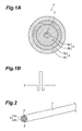
- Fig. 1A is a sectional view of the optical fiber 1 of this embodiment.
- the optical fiber 1 of this embodiment has inside it a glass part (a core 2 and a cladding 3) made of vitreous silica.
- a resin covering layer 4 is formed on the outside of this glass part, and the resin covering layer 4 protects the glass part inside it.
- the cladding 3 is made up of a depressed cladding 3a positioned immediately outside the core 2 and an outer layer cladding 3b outside the depressed cladding 3a. That is, the optical fiber 1 of this embodiment is a double-cladded DCF.
- the diameter of the core 2 is 2.7 ⁇ m
- the outer diameter of the depressed cladding 3a is 6.6 ⁇ m
- the outer diameter of the outer layer cladding 3b (that is, the outer diameter of the glass part) is 120 ⁇ m.
- the resin covering layer 4 is made up of a primary covering layer 4a positioned immediately outside the cladding 3 and a secondary covering layer 4b positioned outside the primary covering layer 4a.
- the thickness of the primary covering layer 4a is 10 ⁇ m
- the thickness of the secondary covering layer 4b is 20 ⁇ m. That is, the outer diameter of the secondary covering layer 4b (the outer diameter of the optical fiber 1) is 180 ⁇ m.
- the primary covering layer 4a and the secondary covering layer 4b of the resin covering layer 4 on the optical fiber 1 are each made of a UV curable resin such as a urethane acrylate, and the primary covering layer 4a is made of a relatively soft resin while the secondary covering layer 4b is made of a relatively hard resin.
- Fig. 1B shows the refractive index distribution of the optical fiber 1 of this embodiment.
- the distribution graph shown in Fig. 1B shows the variation of the refractive index of the core 2 and the depressed cladding 3a with respect to the outer layer cladding 3b.
- the relative index difference (increase) ⁇ + of the core 2 with respect to the outer layer cladding 3b is 1.9%
- the relative index difference (decrease) ⁇ - of the depressed cladding 3a with respect to the outer layer cladding 3b is -0.4%.
- the wavelength-dependent dispersion in the 1.55 ⁇ m wavelength band of this optical fiber 1 is -120ps ⁇ nm -1 ⁇ km -1
- the wavelength-dependent dispersion slope in the 1.55 ⁇ m wavelength band is -0.28ps ⁇ nm -2 ⁇ km -1
- the wavelength-dependent dispersion slope shows the wavelength dependence of the wavelength-dependent dispersion value, and is the gradient of the curve (or straight line) showing the wavelength-dependent dispersion value on a graph in which the horizontal axis is wavelength (nm) and the vertical axis is wavelength-dependent dispersion value (ps ⁇ nm -1 ⁇ km -1 ).
- the transmission loss in the 1.55 ⁇ m wavelength band is 0.40dB/km.
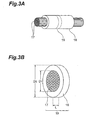
- Fig. 2 is a perspective view of this optical fiber 1.
- the Young's modulus at 23°C of the resin covering layer 4 of the optical fiber 1 of this embodiment was measured by a measurement method which will be discussed hereinafter, it was not greater than 400MPa.
- the Young's modulus measurement method will be explained below. In the following Young's measurement method, if an actual optical fiber is available, the Young's modulus of its covering layer can be measured without a sheet-form sample of the covering layer having to be obtained for the measurement.
- This test tube is then put in an ultrasonic cleaner containing water, for 30 seconds to 3 minutes.
- the length of this time is made the minimum length of time after which it is possible to remove the glass part of the optical fiber from inside the covering layer. This is because if even after it has become possible to remove the glass part of the optical fiber from inside the covering layer the optical fiber is left in the ultrasonic cleaner for longer, the covering layer will break up.
- the optical fiber is taken out of the test tube, which has been taken out of the ultrasonic cleaner, and the glass part is removed from the covering layer. At this time, ample care is taken not to scratch the covering layer. If the covering layer becomes scratched, the procedure must be started again from the beginning.
- the covering layer without the glass part is then held for 30 minutes in a thermostat vacuum tank held at pressure 10kPa (76mmHg) or below, temperature 60°C, to evaporate the solvent. After that, the covering layer is held overnight in a desiccator, and then a tensile test is carried out with the following conditions.
- This Young's modulus measurement method has the object of measuring the Young's modulus of the covering layer from an actual optical fiber. If the covering layer is a single layer, the Young' s modulus obtained by the measurement method described above and the Young's modulus measured using a sheet-form sample are approximately equal. When the covering layer has a multi-layer structure extending from an inner layer to an outer layer in the optical fiber, the Young's modulus obtained by the measurement method described above becomes approximately equal to the Young's modulus of the outermost, hardest covering layer. The reason for this is as follows.
- the Young's modulus obtained is approximately equal to the sheet test value of the material of the covering, and if the covering layer is multi-layer, it is approximately equal to the sheet test value of the material of the hardest, outer covering layer among the multiple layers.
- the Young' s modulus of the primary covering layer (inner layer covering) 4a of the optical fiber 1 of this embodiment was measured by the PIM method, it was not greater than 0.8MPa.
- the PIM Young's modulus measurement method will be explained below. In this case also, if an actual optical fiber is available, the Young's modulus of its covering layer can be measured without a sheet-form sample of the covering layer having to be obtained for the measurement.
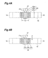
- Fig. 3A is a perspective view illustrating a method for preparing a sample for PIM-method Young's modulus measurement
- Fig. 3B is a perspective view of the sample.
- 17 is an optical fiber to be the object of measurement
- 18 a pipe
- 19 the sample.
- the pipe 18 is made of acrylic resin. Enough optical fibers 17 to substantially fill the pipe 18 are inserted into the pipe 18, and an adhesive consisting of an epoxy resin is poured into the gaps between the optical fibers 17 and between the inner wall of the pipe 18 and the optical fibers 17, and hardened. Then, the pipe 18 is cut perpendicularly to its axis at two intermediate locations along the pipe 18, to make a disc-shaped sample 19. Both sides of the sample 19 are polished.
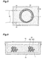
- Fig. 4 is a sectional view illustrating a method for obtaining a relationship between load and displacement for any one of the optical fibers clustered in the sample 19, Fig. 4A showing a state before a load is applied and Fig. 4B showing a state during load application.
- 20 is an optical fiber; 20a the glass part of the optical fiber; 20b an inner layer covering; 20c an outer layer covering; 21 a load-applying pin; and 21a the end face of the load-applying pin 21.
- the load-applying pin 21 is shaped like an inverted truncated cone, and the diameter of its end face 21a is 50 ⁇ m.
- the outer diameter Df of the glass part 20a of the optical fiber 20 is normally 100 ⁇ m, and the outer diameter Dp of the covering 20b is normally 140 ⁇ m.
- the end face 21a of the load-applying pin 21 is brought to abut with the upper end face of the glass part 20a of any of the optical fibers 20 in the sample 19 and a load is applied.
- the glass part 20a and the outer layer covering 20c are made of a material hard enough for their deformation to be negligible compared to that of the inner layer covering 20b, and the amount of deformation caused to them by the applied load is amply small, only the inner layer covering 20b part deforms under the load applied with the load-applying pin 21. As a result, as shown in Fig. 4B, the load-applying pin 21 and the glass part 20a displace downward.
- the Young's modulus of the inner layer covering is obtained using the following formula.
- E (1+.) ⁇ S ⁇ ln(Dp/Df)/( ⁇ L ⁇ Z)
- the sliding friction coefficient of the outermost layer (the secondary covering layer 4b) of the resin covering layer 4 of this embodiment was measured by a measurement method which will be discussed below, it was not greater than 0.20. In this case also, if the following measurement method is used, as long as an actual optical fiber is available, this sliding friction coefficient can be measured without a sheet-form sample of the covering layer having to be obtained for the measurement.
- a specific method for making the sliding friction coefficient of the secondary covering layer 4b less than 0.20 is to add a reactive silicone or a silicone oil such as silicone acrylate resin or the like to the secondary covering layer 4b to make its surface slippery.
- a reactive silicone and a silicone oil may be added.
- the content of the reactive silicone or silicone oil or the like is preferably at least 3%. When it is less than 3%, it is difficult to effectively make the covering layer surface slippery.
- Figs. 5A through 5C are views illustrating a sliding friction coefficient measurement method, Fig. 5A being a top view, Fig. 5B a front view and Fig. 5C a side view.
- 11 is a base member; 12 a base side fiber; 13 a slide member; 14 a slide side fiber; 15 a weight; and 16 a thread.
- the base member 11 has a horizontal, flat upper face and is made of a hard material such as a metal like aluminum or a hard plastic.
- the slide member 13 is a glass plate of length 77mm ⁇ width 28mm ⁇ thickness 1mm and mass 4.9g.
- the weight 15 is of mass 50g.
- the slide side fibers 14 are arranged in parallel without gaps within the groups with their length direction oriented in the width direction of the slide member 13 and affixed to one face of the slide member 13 using double-sided adhesive tape or an adhesive.
- the two groups of slide side fibers 14 are disposed in positions 5mm away from the length direction ends of the slide member 13.
- the refractive index distribution of this optical fiber 1 was similar to that shown in Fig. 2, but the relative index difference (increase) ⁇ + of the core 2 with respect to the outer layer cladding 3b was 1.9%.
- the relative index difference (decrease) ⁇ - of the depressed cladding 3a with respect to the outer layer cladding 3b was -0.4%.
- the Young's modulus of the primary covering layer 4a was 0.98MPa and the Young's modulus of the secondary covering layer 4b was 784MPa (the Young's modulus here was measured using a sheet sample).
- the wavelength-dependent dispersion of this optical fiber 1 in the 1.55 ⁇ m wavelength band was -120ps ⁇ nm -1 ⁇ km -1
- the wavelength-dependent dispersion slope in the 1.55 ⁇ m wavelength band was -0.28ps ⁇ nm -2 ⁇ km -1
- the transmission loss in the 1.55 ⁇ m wavelength band was 0.33dB/km.
- the sliding friction coefficient of the outermost layer (the secondary covering layer 4a) of the optical fiber 1 described above was varied and an experiment was carried out.
- 5km of the optical fiber with its sliding friction coefficient varied was wound on a bobbin of diameter 120mm and then the bobbin was removed and the transmission loss of the coiled optical fiber was measured.
- the signal light used at the time of the measurement was 1.6 ⁇ m, and the temperature at the time of measurement was room temperature (23°C) and -20°C.
- optical fiber cable 10 is shown in Fig. 7.
- the optical fiber cable 10 has inside it the optical fiber 1 described above.
- the optical fiber cable 10 of this embodiment is a cable having one single core optical fiber 1 of the kind described above and is also known as an optical fiber cord.
- the optical fiber cable 10 has at its center the optical fiber 1 described above, and around that is formed a cushioning layer 10a.
- the cushioning layer 10a is made of fibers or the like, and on the outside of this is a covering layer 10b made out of a synthetic resin.
- an optical fiber cable having inside it only a single optical fiber is being taken as an example here, such cables sometimes have a steel wire (high-tensile wire) for taking tensile forces acting on the optical fiber cable and a spacer having a groove for receiving the optical fiber.
- the optical fiber cable may have inside it a plurality of optical fibers, or an optical fiber inside it may be a multi-core optical fiber (a tape-form optical fiber, or optical fiber ribbon).
- An optical fiber cable may with its covering sheath or steel wire exert side pressures and distortion on the optical fiber. And when there are multiple optical fibers, the optical fibers may exert side pressures on each other. However, because as described above the optical fiber 1 does not readily suffer transmission loss increases caused by side pressures and has superior transmission characteristics, the optical fiber cable 10 of this embodiment can also have excellent transmission characteristics.
- the coiled optical fiber 1 is embedded within the filler 84.
- transmission loss increases are also prevented by the optical fiber coil having being removed from the bobbin. Because it has been removed from the bobbin, micro bends forming as a result of the optical fiber 1 being pressed against the bobbin under the winding tension or by adjacent winds of the optical fiber 1 exerting side pressures on each other also tend to be eliminated. And because its coiled state is held by the filler 84, changes in transmission characteristics caused by uncoiling of the optical fiber 1 do not occur either.
- the filler 84 is made up of a fluid part 84a and an elastic solid part 84b.
- the part making contact with the optical fiber 1 is the fluid part 84a, which is liquid or semi-liquid, and outside of this is the elastic solid part 84b, which has some elasticity.
- liquid or semi-liquid refers to a state such that the optical fiber 1 can change its position freely inside the fluid part 84a and such that after it changes its position it essentially is not subjected to a force from the liquid or semi-liquid part tending to return it to the original position.
- a hardening inhibitor in the secondary covering layer 4b of the optical fiber 1 makes it easy to reduce the hardness of only the parts where the fluid part 84a is to be formed, and is very convenient in the manufacture of the optical fiber coil.
- platinum is included in the filler 84 as a hardening reaction catalyst, and an isocyanate compound is used as the hardening inhibitor.
- the combination of a hardening reaction catalyst and a hardening inhibitor for canceling out the action of the catalyst like this utilizes the process of hardening the filler 84 of the optical fiber coil effectively and makes it possible to form the fluid part 84a well.
- the wavelength-dependent dispersion and wavelength-dependent dispersion slope of this DCF were respectively -120ps ⁇ nm -1 ⁇ km -1 and -0.28ps ⁇ nm -2 ⁇ km -1 at wavelength 1.55 ⁇ m, and the transmission loss was 0.40dB/km.
- the Young's modulus of the covering layer 4 was not necessarily 400MPa or less and the Young's modulus of the primary covering layer 4a measured by the PIM method was not necessarily 0.8MPa or less.
- the elastic solid part 84b after hardening is a material whose undisturbed penetration as prescribed by JIS K 2220 is in the range of 5 to 200 over the entire temperature measurement range of -40°C to 100°C.
- the temperature range of -40°C to 100°C is the range of temperatures over which the optical fiber coil is actually used.
- the receiving case may alternatively be doughnut-shaped in form and its bottom may be curved instead of flat.
- the method by which it is manufactured does not have to be the manufacturing method of the embodiment described above.
- the whole of the coiled optical fiber may be dipped in oil to coat the optical fiber with oil and then this may be molded with a filler in the normal way.
- liquid part just the close proximity of the optical fiber may be the liquid part, as described above, or alternatively a single, large, doughnut-shaped liquid part in which the whole coiled optical fiber can be received may be formed.
- An optical fiber coil using a filler having the liquid part or semi-liquid part described above can improve the transmission characteristics of any kind of optical fiber.
- the optical fiber 1 is not limited to an optical fiber having a double cladding type refractive index distribution. It can also be an optical fiber having a refractive index distribution called matched cladding type, double core type or segment core type. And a structure wherein the refractive index of a groove part between a central core and a segment core is made smaller than that of a cladding part can be employed.
- the dispersion-compensating optical fiber was taken to be one having a negative wavelength-dependent dispersion at wavelength 1.55 ⁇ m
- the wavelength-dependent dispersion of the dispersion-compensating optical fiber should be made the opposite sign, i.e. a positive wavelength-dependent dispersion.
- the optical fiber 1 described above was a dispersion-compensating optical fiber (DCF), it may be some other type of optical fiber.
- DCF dispersion-compensating optical fiber
- it may be a single mode optical fiber or a wavelength-dependent dispersion-shifted optical fiber, an NZ wavelength-dependent dispersion-shifted optical fiber, an erbium-doped optical fiber, or a polarization-maintaining optical fiber.
- an optical fiber coil having superior transmission characteristics can be obtained.
- the dispersion-shifted optical fiber is an optical fiber designed for the main purpose of transmitting optical signals in the 1.55 ⁇ m wavelength band. It has the characteristic that its wavelength-dependent dispersion value in the 1.55 ⁇ m wavelength band is zero, but when transmitting with wavelength division multiplexing (hereinafter also referred to as WDM) it suffers the wavelength-dependent dispersion phenomenon on the long and short wavelength sides of this wavelength band.
- a DSF is sometimes used as an optical fiber for Raman scattering excitation. It is sometimes modulized for use.
- the NZ (Non-Zero) dispersion-shifted optical fiber is an optical fiber designed with the center wavelength at which its wavelength-dependent dispersion is zero somewhat shifted from 1.55 ⁇ m to reduce nonlinear effects arising in the case of the above-mentioned DSF. It is the same as the above-mentioned DSF in that the wavelength-dependent dispersion phenomenon occurs in transmission with WDM. It is sometimes modulized for use.
- the erbium-doped optical fiber is an optical fiber whose core has been doped with erbium ions.
- EDF erbium-doped optical fiber
- it is used in a modulized state as an optical amplifier (Erbium-Doped optical Fiber Amplifier, or EDFA) or the like.
- the polarization-maintaining optical fiber is an optical fiber which transmits linearly polarized light with its polarization maintained, and is used in optical fiber gyros and polarization mode dispersion compensators and the like. It is normally used modulized as a PMFM (Polarization-Maintaining optical Fiber Module).
- the Young' s modulus of the covering layer is made not greater than 400MPa, side forces acting on the optical fiber are moderated by the covering layer and their transfer to the glass part is lessened. As a result, it is possible to prevent worsening of transmission loss caused by side pressures and realize superior transmission loss performance.
- the covering of the optical fiber is made double-layer and the Young's modulus of the inner layer covering measured by the PIM method is made not greater than 0.8MPa, because side pressures acting on the outer layer covering are absorbed by the inner layer covering and are not readily transmitted to the glass part, increases in transmission loss caused by coiling can be further reduced.
Landscapes
- Physics & Mathematics (AREA)
- General Physics & Mathematics (AREA)
- Optics & Photonics (AREA)
- Optical Fibers, Optical Fiber Cores, And Optical Fiber Bundles (AREA)
- Surface Treatment Of Glass Fibres Or Filaments (AREA)
- Light Guides In General And Applications Therefor (AREA)
Abstract
Description
- E :
- Young's modulus of inner layer covering (N/mm2)
- ΔS :
- change in load on load-applying pin (mN) (in this case, 75mN-5mN=70mN)
- Dp :
- outer diameter of inner layer covering (µm) =140µm
- Df :
- outer diameter of optical fiber (µm) =100µm
- L :
- thickness of sample (mm) =2mm
- ΔZ :
- change in displacement of load-applying pin(µm)
- · :
- Poisson's ratio (in this case, 0.45)
| Young's Modulus (MPa) | Sliding Friction Coefficient | Transmission Loss (dB/km) | ||
| RoomTemp. (23°C) | -20° | |||
| Embodiment | ||||
| 1 | 400 | 0.18 | 0.33 | 0.38 |
| | 200 | 0.18 | 0.33 | 0.35 |
| | 400 | 0.25 | 0.35 | 0.39 |
| Comp. Ex. 1 | 800 | 0.25 | 0.50 | 1.0 |
| Comp. Ex. 2 | 800 | 0.18 | 0.33 | 0.83 |
- UV resin a:
- relatively soft urethane acrylate resin (Young' s modulus by PIM method: 1.2MPa)
- UV resin b:
- urethane acrylate resin softer still than
UV resin a
(Young's modulus by PIM method: 0.7MPa) - UV resin A:
- relatively hard urethane acrylate resin with silicone acrylate resin added
- UV resin B:
- relatively hard urethane acrylate resin with silicone oil added
- UV resin C:
- relatively hard urethane acrylate resin (no
silicone acrylate resin or silicone oil
added)
Covering Material Sliding Friction Coefficient of Outer Layer Covering Surface Coil State Transmission Loss Increase (dB/km) Inner Layer Covering Outer Layer Covering Ref. Ex. 1 UV resin a UV resin A 0.18 bobbin 0.08 Ref. Ex. 2 UV resin a UV resin A 0.18 no bobbin; filler 0.03 Ref. Ex. 3 UV resin b UV resin A filler 0.18 no bobbin; 0.02 Ref. Ex. 4 UV resin a UV resin B 0.18 no bobbin; filler 0.03 Comp. Ex. 3 UV resin a UV resin C 0.25 bobbin 0.35 Comp. Ex. 4 UV resin a UV resin C 0.25 no bobbin 0.15
| Sliding Friction Coefficient of Outer Layer Covering Surface | Transmission Loss (dB/km) | ||
| RoomTemp. (23°C) | -20°C | ||
| Ref. Ex. 5 | 0.18 | 0.33 | 0.40 |
| Ref. Ex. 6 | 0.17 | 0.33 | 0.39 |
| Comp. Ex. 5 | 0.25 | 0.50 | 0.53 |
Claims (13)
- An optical fiber comprisinga glass part having a core and at least one cladding andat least one covering layer formed around the glass part,wherein the Young's modulus at 23°C of the covering layer, after the glass part is removed from it, is not greater than 400MPa.
- An optical fiber according to claim 1, wherein the covering layer is a double layer made up of an inner layer covering and an outer layer covering and the Young's modulus of the inner layer covering measured by the PIM method is not greater than 0.8MPa.
- An optical fiber according to claim 1, wherein the sliding friction coefficient of the outermost layer of the covering layer is not greater than 0.20.
- An optical fiber according to claim 1, wherein the outermost layer of the covering layer is made of an UV curable resin to which has been added one or both of a silicone oil and a silicone acrylate resin.
- An optical fiber cable having inside it an optical fiber according to claim 1.
- An optical fiber cable according to claim 5, wherein the optical fiber is a dispersion-compensating optical fiber.
- An optical fiber coil made by coiling an optical fiber according to claim 1.
- An optical fiber coil according to claim 7, wherein the optical fiber is a dispersion-compensating optical fiber.
- An optical fiber coil according to claim 7, wherein a filler surrounds the coiled optical fiber and the filler is a resin whose undisturbed penetration prescribed by JIS K 2220 is in the range of 5 to 200 over the entire temperature measurement range of -40°C to 100°C and the filler packs the whole of the optical fiber and holds its coiled state.
- An optical fiber coil comprising an optical fiber, a receiving case receiving the optical fiber in a coiled state, and a filler packed in the receiving case, wherein a part of the filler in contact with the optical fiber is a liquid or semi-liquid fluid part.
- An optical fiber coil according to claim 10, wherein the filler outside the fluid part of the filler is an elastic solid part.
- An optical fiber coil according to claim 11, wherein the fluid part and the elastic solid part of the filler are made from the same material and each have a different hardness.
- An optical fiber coil according to claim 12, wherein the optical fiber has a covering layer and included in the covering layer is a hardening inhibitor for inhibiting hardening of the filler.
Applications Claiming Priority (13)
| Application Number | Priority Date | Filing Date | Title |
|---|---|---|---|
| JP26228199 | 1999-09-16 | ||
| JP26228199 | 1999-09-16 | ||
| JP31521699 | 1999-11-05 | ||
| JP31521699 | 1999-11-05 | ||
| WOPCT/JP00/00026 | 2000-01-06 | ||
| PCT/JP2000/000026 WO2000041011A1 (en) | 1999-01-06 | 2000-01-06 | Dispersion compensating optical fiber |
| JP2000193259 | 2000-06-27 | ||
| JP2000193272 | 2000-06-27 | ||
| JP2000193281 | 2000-06-27 | ||
| JP2000193281A JP3988360B2 (en) | 1999-09-16 | 2000-06-27 | Optical fiber coil |
| JP2000193272 | 2000-06-27 | ||
| JP2000193259A JP2001194564A (en) | 1999-11-05 | 2000-06-27 | Optical fiber, optical fiber cable and optical fiber coil |
| PCT/JP2000/004464 WO2001020384A1 (en) | 1999-09-16 | 2000-07-05 | Optical fiber |
Publications (2)
| Publication Number | Publication Date |
|---|---|
| EP1132759A1 true EP1132759A1 (en) | 2001-09-12 |
| EP1132759A4 EP1132759A4 (en) | 2006-07-19 |
Family
ID=27530406
Family Applications (1)
| Application Number | Title | Priority Date | Filing Date |
|---|---|---|---|
| EP00944261A Withdrawn EP1132759A4 (en) | 1999-09-16 | 2000-07-05 | OPTICAL FIBER |
Country Status (5)
| Country | Link |
|---|---|
| US (1) | US6597846B1 (en) |
| EP (1) | EP1132759A4 (en) |
| KR (1) | KR100709496B1 (en) |
| CN (1) | CN1214266C (en) |
| WO (1) | WO2001020384A1 (en) |
Cited By (2)
| Publication number | Priority date | Publication date | Assignee | Title |
|---|---|---|---|---|
| US6707977B2 (en) | 2001-03-15 | 2004-03-16 | Corning Incorporated | All fiber polarization mode dispersion compensator |
| US6785455B2 (en) | 2001-01-23 | 2004-08-31 | Sumitomo Electric Industries, Ltd. | Dispersion compensation unit and method of producing the same |
Families Citing this family (6)
| Publication number | Priority date | Publication date | Assignee | Title |
|---|---|---|---|---|
| AU2001289943A1 (en) * | 2000-10-09 | 2002-04-22 | Bayer Aktiengesellschaft | Complexes for transferring nucleic acids into cells |
| GB0204309D0 (en) * | 2002-02-25 | 2002-04-10 | Ibm | Usage charging |
| US7272289B2 (en) * | 2005-09-30 | 2007-09-18 | Corning Incorporated | Low bend loss optical fiber |
| JP5638745B2 (en) * | 2008-08-07 | 2014-12-10 | 古河電気工業株式会社 | Fiber optic cable |
| JP4653213B2 (en) | 2008-12-25 | 2011-03-16 | 古河電気工業株式会社 | Fiber optic cable |
| US9766420B2 (en) | 2013-03-15 | 2017-09-19 | Joe Denton Brown | Apparatus and method for absorbing laser energy that fails to couple into the core of a laser fiber, and for absorbing the energy that has been transmitted to the cladding of the laser |
Family Cites Families (15)
| Publication number | Priority date | Publication date | Assignee | Title |
|---|---|---|---|---|
| JPS58116502A (en) * | 1981-12-29 | 1983-07-11 | Fujitsu Ltd | Fiber for optical transmission |
| JPH0629888B2 (en) * | 1984-07-23 | 1994-04-20 | 古河電気工業株式会社 | Coated optical fiber |
| JPS632008A (en) * | 1986-06-23 | 1988-01-07 | Sumitomo Electric Ind Ltd | Resin coated optical fiber strand |
| JPH0425685Y2 (en) * | 1986-09-09 | 1992-06-19 | ||
| JPS63306406A (en) * | 1987-06-08 | 1988-12-14 | Nippon Telegr & Teleph Corp <Ntt> | Coated optical fiber and its production |
| JP2536236B2 (en) * | 1990-05-17 | 1996-09-18 | 三菱電機株式会社 | solenoid valve |
| US5546482A (en) * | 1993-04-19 | 1996-08-13 | Litton Systems, Inc. | Potted fiber optic gyro sensor coil for stringent vibration and thermal enviroments |
| JPH1010378A (en) * | 1996-06-25 | 1998-01-16 | Toshiba Corp | Optical fiber core, optical fiber coil, and method of manufacturing optical fiber core |
| JPH10115727A (en) * | 1996-08-20 | 1998-05-06 | Furukawa Electric Co Ltd:The | Dispersion compensating optical fiber |
| JPH10123342A (en) | 1996-10-24 | 1998-05-15 | Sumitomo Electric Ind Ltd | Chromatic dispersion compensator and method of manufacturing chromatic dispersion compensator |
| JPH10307240A (en) * | 1997-05-06 | 1998-11-17 | Furukawa Electric Co Ltd:The | Optical fiber |
| JPH11149020A (en) * | 1997-11-17 | 1999-06-02 | Fujikura Ltd | Optical fiber cord |
| JPH11194242A (en) * | 1998-01-07 | 1999-07-21 | Fujikura Ltd | Optical fiber |
| WO2000041011A1 (en) * | 1999-01-06 | 2000-07-13 | Sumitomo Electric Industries, Ltd. | Dispersion compensating optical fiber |
| CA2440938A1 (en) * | 2001-03-16 | 2002-09-26 | Sumitomo Electric Industries, Ltd. | Optical fiber and method of manufacturing the same |
-
2000
- 2000-07-05 WO PCT/JP2000/004464 patent/WO2001020384A1/en not_active Ceased
- 2000-07-05 KR KR1020017006116A patent/KR100709496B1/en not_active Expired - Fee Related
- 2000-07-05 EP EP00944261A patent/EP1132759A4/en not_active Withdrawn
- 2000-07-05 CN CNB008022631A patent/CN1214266C/en not_active Expired - Fee Related
- 2000-08-05 US US09/831,308 patent/US6597846B1/en not_active Expired - Lifetime
Cited By (2)
| Publication number | Priority date | Publication date | Assignee | Title |
|---|---|---|---|---|
| US6785455B2 (en) | 2001-01-23 | 2004-08-31 | Sumitomo Electric Industries, Ltd. | Dispersion compensation unit and method of producing the same |
| US6707977B2 (en) | 2001-03-15 | 2004-03-16 | Corning Incorporated | All fiber polarization mode dispersion compensator |
Also Published As
| Publication number | Publication date |
|---|---|
| KR100709496B1 (en) | 2007-04-20 |
| US6597846B1 (en) | 2003-07-22 |
| CN1335942A (en) | 2002-02-13 |
| WO2001020384A1 (en) | 2001-03-22 |
| KR20010101009A (en) | 2001-11-14 |
| CN1214266C (en) | 2005-08-10 |
| EP1132759A4 (en) | 2006-07-19 |
Similar Documents
| Publication | Publication Date | Title |
|---|---|---|
| JP4010113B2 (en) | Dispersion compensator and manufacturing method thereof | |
| US20040213531A1 (en) | Optical fiber, optical fiber tape, optical cable and optical connector with optical fiber | |
| EP3868728A1 (en) | Optical fiber | |
| US20120189257A1 (en) | Optical fiber, optical fiber ribbon and optical fiber cable | |
| US7043131B2 (en) | Optical device and a making method thereof | |
| JPWO2000041011A1 (en) | Dispersion compensator and manufacturing method thereof | |
| US6597846B1 (en) | Optical fiber | |
| US20230393332A1 (en) | Optical fiber cable | |
| EP3869252A1 (en) | Optical fiber | |
| US7233728B2 (en) | Dispersion compensating optical fiber | |
| AU772564B2 (en) | Optical fiber | |
| KR100589301B1 (en) | Dispersion compensator | |
| JP4861181B2 (en) | High performance index dispersion compensating fiber for standard single mode fiber and transmission system using the dispersion compensating fiber | |
| CA2350457A1 (en) | Optical fiber | |
| US6608954B2 (en) | Optical fiber coil and manufacturing method thereof | |
| JP3988360B2 (en) | Optical fiber coil | |
| JP2002082263A (en) | Optical fiber, optical fiber coil, dispersion compensating fiber, dispersion compensator, and optical fiber transmission line | |
| JP2001194564A (en) | Optical fiber, optical fiber cable and optical fiber coil | |
| EP4231072A1 (en) | Optical fiber cable | |
| JP2004020854A (en) | Optical components | |
| JP2001194565A (en) | Optical fiber, optical fiber cable and optical fiber coil | |
| JP2002333555A (en) | Optical fiber, optical fiber coil, optical fiber coil unit, optical fiber transmission line, and method for manufacturing optical fiber | |
| JP2001290031A (en) | Optical fiber coil and method of manufacturing the same | |
| US20040001681A1 (en) | Optical fiber, dispersion compensator, and optical transmission system | |
| JP2001194537A (en) | Optical fiber coil |
Legal Events
| Date | Code | Title | Description |
|---|---|---|---|
| PUAI | Public reference made under article 153(3) epc to a published international application that has entered the european phase |
Free format text: ORIGINAL CODE: 0009012 |
|
| 17P | Request for examination filed |
Effective date: 20010613 |
|
| AK | Designated contracting states |
Kind code of ref document: A1 Designated state(s): AT BE CH CY DE DK ES FI FR GB GR IE IT LI LU MC NL PT SE |
|
| AX | Request for extension of the european patent |
Free format text: AL;LT;LV;MK;RO;SI |
|
| RBV | Designated contracting states (corrected) |
Designated state(s): DE DK FR GB IT SE |
|
| A4 | Supplementary search report drawn up and despatched |
Effective date: 20060616 |
|
| RIC1 | Information provided on ipc code assigned before grant |
Ipc: G02B 6/44 20060101AFI20010329BHEP Ipc: G02B 6/36 20060101ALI20060609BHEP |
|
| 17Q | First examination report despatched |
Effective date: 20060630 |
|
| GRAP | Despatch of communication of intention to grant a patent |
Free format text: ORIGINAL CODE: EPIDOSNIGR1 |
|
| STAA | Information on the status of an ep patent application or granted ep patent |
Free format text: STATUS: THE APPLICATION IS DEEMED TO BE WITHDRAWN |
|
| 18D | Application deemed to be withdrawn |
Effective date: 20091229 |