EP1132738B1 - Evaporative light scattering device - Google Patents
Evaporative light scattering device Download PDFInfo
- Publication number
- EP1132738B1 EP1132738B1 EP01105606A EP01105606A EP1132738B1 EP 1132738 B1 EP1132738 B1 EP 1132738B1 EP 01105606 A EP01105606 A EP 01105606A EP 01105606 A EP01105606 A EP 01105606A EP 1132738 B1 EP1132738 B1 EP 1132738B1
- Authority
- EP
- European Patent Office
- Prior art keywords
- nebulizer
- impactor
- flow
- drift tube
- retractable
- Prior art date
- Legal status (The legal status is an assumption and is not a legal conclusion. Google has not performed a legal analysis and makes no representation as to the accuracy of the status listed.)
- Expired - Lifetime
Links
- 238000000105 evaporative light scattering detection Methods 0.000 title claims abstract description 23
- 239000006199 nebulizer Substances 0.000 claims abstract description 39
- 238000004891 communication Methods 0.000 claims abstract description 6
- 238000001704 evaporation Methods 0.000 claims description 11
- 239000012530 fluid Substances 0.000 claims description 4
- 238000006243 chemical reaction Methods 0.000 claims description 3
- 239000002245 particle Substances 0.000 description 18
- 238000004587 chromatography analysis Methods 0.000 description 17
- 230000008020 evaporation Effects 0.000 description 10
- 238000001514 detection method Methods 0.000 description 8
- 239000007789 gas Substances 0.000 description 8
- 238000002663 nebulization Methods 0.000 description 7
- IJGRMHOSHXDMSA-UHFFFAOYSA-N Atomic nitrogen Chemical compound N#N IJGRMHOSHXDMSA-UHFFFAOYSA-N 0.000 description 6
- 238000009833 condensation Methods 0.000 description 4
- 230000005494 condensation Effects 0.000 description 4
- 239000002699 waste material Substances 0.000 description 4
- 239000000443 aerosol Substances 0.000 description 3
- 238000000149 argon plasma sintering Methods 0.000 description 3
- 238000000034 method Methods 0.000 description 3
- 229910052757 nitrogen Inorganic materials 0.000 description 3
- 230000003287 optical effect Effects 0.000 description 3
- 229910001220 stainless steel Inorganic materials 0.000 description 3
- 239000010935 stainless steel Substances 0.000 description 3
- CURLTUGMZLYLDI-UHFFFAOYSA-N Carbon dioxide Chemical compound O=C=O CURLTUGMZLYLDI-UHFFFAOYSA-N 0.000 description 2
- 230000008901 benefit Effects 0.000 description 2
- 230000001427 coherent effect Effects 0.000 description 2
- 238000005227 gel permeation chromatography Methods 0.000 description 2
- 229920000642 polymer Polymers 0.000 description 2
- 230000001105 regulatory effect Effects 0.000 description 2
- 230000035945 sensitivity Effects 0.000 description 2
- XUIMIQQOPSSXEZ-UHFFFAOYSA-N Silicon Chemical compound [Si] XUIMIQQOPSSXEZ-UHFFFAOYSA-N 0.000 description 1
- 239000004809 Teflon Substances 0.000 description 1
- 229920006362 Teflon® Polymers 0.000 description 1
- 239000003570 air Substances 0.000 description 1
- XAGFODPZIPBFFR-UHFFFAOYSA-N aluminium Chemical compound [Al] XAGFODPZIPBFFR-UHFFFAOYSA-N 0.000 description 1
- 229910052782 aluminium Inorganic materials 0.000 description 1
- 235000001014 amino acid Nutrition 0.000 description 1
- 150000001413 amino acids Chemical class 0.000 description 1
- 150000001720 carbohydrates Chemical class 0.000 description 1
- 235000014633 carbohydrates Nutrition 0.000 description 1
- 229910002092 carbon dioxide Inorganic materials 0.000 description 1
- 239000001569 carbon dioxide Substances 0.000 description 1
- 239000000356 contaminant Substances 0.000 description 1
- 238000010586 diagram Methods 0.000 description 1
- 235000014113 dietary fatty acids Nutrition 0.000 description 1
- 239000003814 drug Substances 0.000 description 1
- 150000004665 fatty acids Chemical class 0.000 description 1
- 238000001825 field-flow fractionation Methods 0.000 description 1
- 230000005484 gravity Effects 0.000 description 1
- 239000001307 helium Substances 0.000 description 1
- 229910052734 helium Inorganic materials 0.000 description 1
- SWQJXJOGLNCZEY-UHFFFAOYSA-N helium atom Chemical compound [He] SWQJXJOGLNCZEY-UHFFFAOYSA-N 0.000 description 1
- 238000004128 high performance liquid chromatography Methods 0.000 description 1
- 150000002632 lipids Chemical class 0.000 description 1
- 238000012986 modification Methods 0.000 description 1
- 230000004048 modification Effects 0.000 description 1
- 239000003921 oil Substances 0.000 description 1
- 238000004810 partition chromatography Methods 0.000 description 1
- 229910052710 silicon Inorganic materials 0.000 description 1
- 239000010703 silicon Substances 0.000 description 1
- 239000007787 solid Substances 0.000 description 1
- 239000000126 substance Substances 0.000 description 1
- 238000004808 supercritical fluid chromatography Methods 0.000 description 1
- 239000004094 surface-active agent Substances 0.000 description 1
- BFKJFAAPBSQJPD-UHFFFAOYSA-N tetrafluoroethene Chemical compound FC(F)=C(F)F BFKJFAAPBSQJPD-UHFFFAOYSA-N 0.000 description 1
- 150000003626 triacylglycerols Chemical class 0.000 description 1
- 238000009423 ventilation Methods 0.000 description 1
- XLYOFNOQVPJJNP-UHFFFAOYSA-N water Substances O XLYOFNOQVPJJNP-UHFFFAOYSA-N 0.000 description 1
Images


Classifications
-
- G—PHYSICS
- G01—MEASURING; TESTING
- G01N—INVESTIGATING OR ANALYSING MATERIALS BY DETERMINING THEIR CHEMICAL OR PHYSICAL PROPERTIES
- G01N30/00—Investigating or analysing materials by separation into components using adsorption, absorption or similar phenomena or using ion-exchange, e.g. chromatography or field flow fractionation
- G01N30/02—Column chromatography
- G01N30/62—Detectors specially adapted therefor
- G01N30/74—Optical detectors
-
- G—PHYSICS
- G01—MEASURING; TESTING
- G01N—INVESTIGATING OR ANALYSING MATERIALS BY DETERMINING THEIR CHEMICAL OR PHYSICAL PROPERTIES
- G01N15/00—Investigating characteristics of particles; Investigating permeability, pore-volume or surface-area of porous materials
- G01N15/06—Investigating concentration of particle suspensions
- G01N15/065—Investigating concentration of particle suspensions using condensation nuclei counters
-
- G—PHYSICS
- G01—MEASURING; TESTING
- G01N—INVESTIGATING OR ANALYSING MATERIALS BY DETERMINING THEIR CHEMICAL OR PHYSICAL PROPERTIES
- G01N15/00—Investigating characteristics of particles; Investigating permeability, pore-volume or surface-area of porous materials
- G01N15/02—Investigating particle size or size distribution
- G01N15/0255—Investigating particle size or size distribution with mechanical, e.g. inertial, classification, and investigation of sorted collections
- G01N2015/0261—Investigating particle size or size distribution with mechanical, e.g. inertial, classification, and investigation of sorted collections using impactors
-
- G—PHYSICS
- G01—MEASURING; TESTING
- G01N—INVESTIGATING OR ANALYSING MATERIALS BY DETERMINING THEIR CHEMICAL OR PHYSICAL PROPERTIES
- G01N30/00—Investigating or analysing materials by separation into components using adsorption, absorption or similar phenomena or using ion-exchange, e.g. chromatography or field flow fractionation
- G01N30/02—Column chromatography
- G01N30/84—Preparation of the fraction to be distributed
- G01N2030/8447—Nebulising, aerosol formation or ionisation
- G01N2030/847—Nebulising, aerosol formation or ionisation by pneumatic means
-
- G—PHYSICS
- G01—MEASURING; TESTING
- G01N—INVESTIGATING OR ANALYSING MATERIALS BY DETERMINING THEIR CHEMICAL OR PHYSICAL PROPERTIES
- G01N30/00—Investigating or analysing materials by separation into components using adsorption, absorption or similar phenomena or using ion-exchange, e.g. chromatography or field flow fractionation
- G01N30/02—Column chromatography
- G01N30/84—Preparation of the fraction to be distributed
- G01N2030/8447—Nebulising, aerosol formation or ionisation
- G01N2030/8494—Desolvation chambers
Definitions
- Evaporative light scattering detection is a method of detecting samples that have been previously separated in various chromatography methods such as, for example, High Performance Liquid Chromatography (HPLC), Gel-Permeation Chromatography (GPC), High Performance Centrifugal Partition Chromatography (HPCPC), Field Flow Fractionation (FFF), and Supercritical Fluid Chromatography (SFC).
- HPLC High Performance Liquid Chromatography
- GPC Gel-Permeation Chromatography
- HPPC High Performance Centrifugal Partition Chromatography
- FFF Field Flow Fractionation
- SFC Supercritical Fluid Chromatography
- Evaporative light scattering detection is preferably used when the sample components (e.g., components to be detected) have lower volatility than the mobile phase.
- sample components e.g., components to be detected
- sample types include, for example, lipids, triglycerides, surfactants, polymers, underivatized fatty and amino acids, carbohydrates and pharmaceuticals.
- evaporative light scattering detection involves four main steps: 1) nebulization of the chromatography effluent, (which consists of the mobile phase and the sample), into an aerosol of particles, 2) evaporation of the mobile phase, 3) directing a light beam at the dry sample particles to scatter the light, and 4) detection of the scattered light. The amount of sample is determined based upon on how much light is scattered.
- a single flow design the nebulized chromatography effluent is immediately introduced into a heated drift tube where the mobile phase is evaporated. The sample particles are then flowed from the heated drift tube to an optical cell where light scattering and detection occurs.
- the Alltech Model 500 ELSD is sold by the assignee of this application, ALLTECH ASSOCIATES, INC.
- the nebulized chromatography effluent is first flowed through a nebulization chamber before entering the heated drift tube.
- the nebulized chromatography effluent is split, namely, the larger droplets are eliminated by condensation/impaction on the walls of the nebulization chamber. This condensate is drained to waste. Only the smaller nebulized droplets are subsequently flowed to the heated drift tube where the mobile phase (which is now free of the larger droplets) is more easily evaporated. Thereafter, the sample particles are flowed to the optical cell for light scattering and detection.
- Devices of this design type are available from, for example, POLYMER LABORATORIES, SEDERE or EUROPSEP INSTRUMENTS.
- the above-described design types have particular advantages depending on the mobile phase and the sample type.
- the single flow design is preferred for use in applications involving the detection of relatively non-volatile samples in relatively volatile organic mobile phases. Moreover, because the entire sample enters the optical cell in this design, response and sensitivity is maximized.
- the single flow design is not especially preferred when detecting relatively volatile samples in relatively non-volatile mobile phases (such as aqueous mobile phases).
- Highly aqueous mobile phases generally require higher evaporation temperatures. If the sample is volatile at these higher evaporation temperatures, sample loss is incurred during the evaporation step resulting in poorer sensitivity.
- the split-flow design i.e., passing the chromatography effluent through a nebulization chamber to remove the larger droplets of mobile phase prior to the heated drift tube
- the evaporation temperature of the mobile phase can be reduced.
- the mobile phase may be evaporated at a lower temperature in the drift tube, which leads to less sample loss from evaporation.
- a smaller and more uniform particle size distribution is achieved in the mobile phase, which enables evaporation of the mobile phase at lower evaporation temperatures.
- the split-flow design is generally less preferred because (1) loss of the relatively non-volatile sample during evaporation at lower temperatures of the relatively volatile mobile phase is not a concern (2) the relatively non-volatile sample may be lost during the splitting of the chromatography effluent in the nebulization chamber.
- Another problem with devices of the split-flow design is that the split ratio of the sample (i.e., the amount that goes to waste versus the amount that is ultimately detected) is affected by, among other things, the laboratory temperature. In other words, fluctuations in laboratory temperatures may lead to fluctuations in droplet size in the nebulized chromatography effluent. Thus, as ambient and/or laboratory temperatures fluctuate, the split ratio and corresponding reproducibility of sample detection may vary from run to run.
- Fig 1 illustrates an evaporative light scattering detection device of the single flow configuration.
- Fig. 1 provides an overview of the principal of operation of an evaporative light scattering detection device 10.
- the evaporative light scattering device 10 has a connector 12.
- the connector 12 provides a fluid connection between the chromatography column (not shown) and the evaporative light scattering device 10.
- the connector 12 is preferably made from stainless steel and is threadingly engaged to nebulizer bracket 16. Chromatography effluent is flowed into the evaporative light scattering device 10 through channel 13 in connector 12.
- Nebulizer bracket 16 removably attaches nebulizer 14 to drift tube assembly 18.
- the nebulizer 14 contains a nebulizer needle (not shown).
- the drift tube assembly 18 surrounds a central heated drift tube channel 11.
- a laser light source 20, a photodetector 22 and amplifier 24 are provided.
- the chromatography effluent is flowed through connector 12 to nebulizer 14.
- the chromatography effluent is directed through the nebulizer needle (not shown).
- the chromatography effluent is impacted by nebulizer gas to form an aerosol of droplets, preferably of generally uniform size.
- the nebulizing gas may Include any gas that is Inert to the sample such as helium, carbon dioxide, air or nitrogen, and is preferably nitrogen.
- the nebulized chromatography effluent is then flowed through channel 11 in the drift tube assembly 18.
- the mobile phase is evaporated leaving behind the relatively non-volatile sample particles.
- the sample particles are flowed through channel 11 to the light scattering zone 19 for detection.
- a light source 20 emits light, which the sample particles scatter.
- the scattered light Is then detected at the photodetector 22.
- the photodetector 22 then produces a signal, which Is sent to an amplifier 24 though analog outputs In the photodetector.
- the light source 20 Is preferably a Class IIIA laser product with 650 nm laser diode, 5mW maximum power, collimating optics, and polarized.
- a preferred laser light source is available from COHERENT, as part no. VLM3-5L.
- the photodetector 22 is preferably made from a silicon photodiode.
- a preferred photodetector 22 Is available from HAMAMATSU, as part no. S2386-8K.
- the photodetector 22 is preferably located at a 90-degree angle from the light source 20.
- a light trap (not shown) is also preferably located at a 180-degree angle from the light source 20 to collect any light not scattered by the sample particles In the aerosol stream. After detection in the detection zone, the sample particles are flowed to waste.
- the exhaust is flowed to a fumed hood or other ventilation device located close to the detector to remove the detector exhaust from the laboratory.
- the nitrogen nebulizing gas is preferably regulated from 310-552 kPa (Gauge) (45-80 psig) with 99.9% purity or better. A stable gas flowrate and pressure are necessary for reproducible results.
- the gas is preferably free of contaminants, such as oil, water, particulate or any other non-volatile substances.
- the droplet size in the nebulized chromatography effluent may be regulated by varying the flow rate of either the chromatography effluent and/or the nebulizing gas. The lower the flow rate of the chromatography effluent, the less gas and heat necessary for nebulization and subsequent evaporation
- a device for evaporative light scattering detection wherein a sample to be detected is flowed through the device, the device comprising a nebuliser, a drift tube in flow communication with the nebulizer, the drift tube positioned downstream in the direction of flow from the nebuliser, a light source positioned downstream of the drift tube, and a detector to detect the sample by evaporative light scattering, the detector characterized by a retractable impactor for easy conversion between a single flow configuration and a split flow configuration positioned in the drift tube, and the drift tube further comprising a drain outlet.
- the device comprises a nebulizer 102.
- the nebulizer is preferably as disclosed in co-pending application serial no. 08/932,262 and is available from ALL TECH ASSOCIATES, part no. 600514. Downstream in the direction of flow from the nebulizer is a tube 104.
- the drift tube may preferably be constructed as set forth in co-pending application serial no. 08/932,262.
- the drift tube has two sections, a nebulizer block 106 and a mid-section 108.
- the nebulizer block 106 connects the nebulizer 102 to the drift tube.
- the nebulizer 102 is in flow communication with the drift tube 104.
- the drift tube 104 further has a drain outlet 110, which is preferably located on the nebulizer block 106.
- the drift tube also has a retractable impactor 105, which is also preferably located on the nebulizer block 106.
- the impactor 105 preferably comprises a planar, solid section 105a mounted on a pin 105b. By retractable, it is meant that the planar section 105a may be rotated from a position where the face of the planar section is parallel to the direction of fluid flow (parallel mode) to a position in which the face of the planar section is at a 90 degree angle to the path of flow (perpendicular mode) through the drift tube 104.
- the planar section When in the perpendicular mode, the planar section provides an impact surface for the nebulized mobile phase particles to strike, which leads to condensation of those particles.
- the drift tube is positioned at an angle such that the drain outlet is below the impactor relative a plane X-X through the device between the impactor and the drain outlet, condensed mobile phase is removed from the device by gravity through the drain outlet 110.
- the planar section 105a is tapered (see Fig. 4 ) and is constructed from TEFLON coated stainless steel.
- the outer edges of the planar section 105 c and generally correspond to the contour of the inner wall 104a of the drift tube.
- the impactor pin is preferably constructed from stainless steel.
- the impactor In the perpendicular mode, the impactor preferably blocks about 70% of the flow path in the plane through the drift tube in which the impactor planar section 105a resides.
- the impactor In the parallel mode, the impactor preferably blocks about 18% of the flow path in the plane through the drift tube in which the impactor planar section 105a resides.
- the impactor is preferably tapered (see Figure 5 ), most of the mobile phase and sample will flow past the impactor when it is in its parallel mode.
- the impactor is preferably rotated between the parallel and perpendicular modes by a motor (not shown), such as a direct drive solenoid motor.
- a motor such as a direct drive solenoid motor.
- the impactor may be rotated manually if desired.
- rotation of the impactor may be programmed by the user and driven by logic.
- the device may be constructed such that the impactor is inserted and retracted from the fluid flow channel instead of rotated between the perpendicular and parallel modes as described above.
- the impactor may be inserted into the flow channel of the drift tube and positioned in the perpendicular mode and removed from the flow channel all together by appropriate means.
- the term "retractable” is meant to include the above described impactor that may be rotated between the perpendicular and parallel modes as well as to an impactor that may be inserted into the flow channel and positioned in the perpendicular mode and removed from the flow channel all together.
- the shape of the impactor may be varied.
- the only critical aspect of the impactor is that it provide a sufficient impact surface for the nebulized mobile phase when the device is in the split flow configuration and that this impact surface may be easily removed from the path of flow for converting to the single flow configuration.
- the drift tube 104 is in flow communication with an optics block 112.
- the optics block comprises a light source 114, which is preferably a laser available from COHERENT as part VLMIII-5L, and a light trap 116.
- the light trap is preferably an insulated block of black anodized aluminum of suitable curvature to funnel light to its end.
- the device further comprises a detector 118, which comprises a photo diode and amplifier available from ELECTRO-OPTICAL SYSTEMS as part no. S-050-E8.
- the drift tube 104 and optics block 112 are in flow communication with an exhaust tube 122.
- the impactor 105 is in the parallel mode ( Fig 3 ).
- the sample and mobile phase are introduced into the nebulizer 102 where the sample and mobile phase are nebulized.
- the sample and mobile phase particles are then flowed to the drift tube where the mobile phase is evaporated.
- the sample particles are then flowed to the optics block where the sample particles are detected.
- the sample particles are then flowed to the exhaust tube 122 and then to waste.
- the device may be quickly and easily converted to the split flow configuration by placing the impactor in the perpendicular mode ( Fig. 4 ).
- sample and mobile phase are nebulized in the nebulizer.
- the nebulized sample and mobile phase strike the planar section 105a of the impactor, which removes a portion of the nebulized mobile phase (and possible a portion of the sample) from the flow stream by condensation.
- This condensate is flowed out of the drift tube through drain outlet 110.
- the remaining portion of the sample and mobile phase is flowed through the drift tube where the mobile phase is evaporated.
- the sample particles are then flowed to the optics block where the sample is detected.
- the device has four zones in which the temperature is controlled independently of the other zones.
- the first zone is located between the nebulizer 102 and the impactor 105.
- the second zone is located between the impactor 105 and the optics block 112.
- the third zone is the optics block 112.
- the fourth zone is the exhaust tube.
- the zones are heated by using heat tape embedded in the nebulizer block, drift tube, optics block and the exhaust tube as well known in the art.
- each of these zones is connected to their own power source for independent temperature control. As those skilled in the art will appreciate, optimum temperature conditions for the particular sample and mobile phase are more easily achieved by dividing the device into four temperature zones.
- the evaporative light scattering device may have the following dimensions.
- the distance between the tip of the nebulizer needle to the end of the exhaust tube 122 is 600,13 mm (23,627 inches).
- the distance from the tip of the nebulizer needle to the impactor 105 is 68,89 mm (2,594 inches).
- the nebulizer block 106 is 90,78 mm (3,574 inches) in length.
- the mid-section of the drift tube 104 is about 330,2 mm (13 inches) in length.
- the length of the exhaust tube is 10,19 mm (4,388 inches).
- the internal diameter of the drift tube 104 is about 22,10 mm (0,87 inches).
- the impactor 105 preferably has the following dimensions.
- edges 105f are about 0,40 mm (0,016 inches) in length.
- the impactor has a thickness of about 2,31 mm (0,091 inches) along line 105g.
- Bore 105h has an internal diameter of about 71,01 mm (0,276 inches) for receiving mounting needle 105b.
- the impactor 105 further has a width of about 14,02 mm (0,552 inches) along line 105i.
Landscapes
- Physics & Mathematics (AREA)
- Spectroscopy & Molecular Physics (AREA)
- Health & Medical Sciences (AREA)
- Life Sciences & Earth Sciences (AREA)
- Chemical & Material Sciences (AREA)
- Analytical Chemistry (AREA)
- Biochemistry (AREA)
- General Health & Medical Sciences (AREA)
- General Physics & Mathematics (AREA)
- Immunology (AREA)
- Pathology (AREA)
- Investigating Or Analysing Materials By Optical Means (AREA)
- Examining Or Testing Airtightness (AREA)
- Optical Measuring Cells (AREA)
Abstract
Description
- Evaporative light scattering detection is a method of detecting samples that have been previously separated in various chromatography methods such as, for example, High Performance Liquid Chromatography (HPLC), Gel-Permeation Chromatography (GPC), High Performance Centrifugal Partition Chromatography (HPCPC), Field Flow Fractionation (FFF), and Supercritical Fluid Chromatography (SFC). Evaporative light scattering detection is preferably used when the sample components (e.g., components to be detected) have lower volatility than the mobile phase. A wide variety of sample types can be detected in evaporative light scattering detection. Such sample types include, for example, lipids, triglycerides, surfactants, polymers, underivatized fatty and amino acids, carbohydrates and pharmaceuticals.
- Generally, evaporative light scattering detection involves four main steps: 1) nebulization of the chromatography effluent, (which consists of the mobile phase and the sample), into an aerosol of particles, 2) evaporation of the mobile phase, 3) directing a light beam at the dry sample particles to scatter the light, and 4) detection of the scattered light. The amount of sample is determined based upon on how much light is scattered. There are two principal types of devices used in evaporative light scattering detection known in the art. In the first type (the "single flow" design), the nebulized chromatography effluent is immediately introduced into a heated drift tube where the mobile phase is evaporated. The sample particles are then flowed from the heated drift tube to an optical cell where light scattering and detection occurs. One such example of this type of device (the Alltech Model 500 ELSD) is sold by the assignee of this application, ALLTECH ASSOCIATES, INC.
- In the second type of device, (the "split-flow" design), the nebulized chromatography effluent is first flowed through a nebulization chamber before entering the heated drift tube. In the nebulization chamber, the nebulized chromatography effluent is split, namely, the larger droplets are eliminated by condensation/impaction on the walls of the nebulization chamber. This condensate is drained to waste. Only the smaller nebulized droplets are subsequently flowed to the heated drift tube where the mobile phase (which is now free of the larger droplets) is more easily evaporated. Thereafter, the sample particles are flowed to the optical cell for light scattering and detection. Devices of this design type are available from, for example, POLYMER LABORATORIES, SEDERE or EUROPSEP INSTRUMENTS.
- The above-described design types have particular advantages depending on the mobile phase and the sample type. The single flow design is preferred for use in applications involving the detection of relatively non-volatile samples in relatively volatile organic mobile phases. Moreover, because the entire sample enters the optical cell in this design, response and sensitivity is maximized.
- However, the single flow design is not especially preferred when detecting relatively volatile samples in relatively non-volatile mobile phases (such as aqueous mobile phases). Highly aqueous mobile phases generally require higher evaporation temperatures. If the sample is volatile at these higher evaporation temperatures, sample loss is incurred during the evaporation step resulting in poorer sensitivity. By using the split-flow design (i.e., passing the chromatography effluent through a nebulization chamber to remove the larger droplets of mobile phase prior to the heated drift tube), the evaporation temperature of the mobile phase can be reduced. Thus, the mobile phase may be evaporated at a lower temperature in the drift tube, which leads to less sample loss from evaporation. In other words, by removing the larger droplets, a smaller and more uniform particle size distribution is achieved in the mobile phase, which enables evaporation of the mobile phase at lower evaporation temperatures.
- However, for relatively non-volatile sample types in relatively volatile organic mobile phases, the split-flow design is generally less preferred because (1) loss of the relatively non-volatile sample during evaporation at lower temperatures of the relatively volatile mobile phase is not a concern (2) the relatively non-volatile sample may be lost during the splitting of the chromatography effluent in the nebulization chamber. Another problem with devices of the split-flow design is that the split ratio of the sample (i.e., the amount that goes to waste versus the amount that is ultimately detected) is affected by, among other things, the laboratory temperature. In other words, fluctuations in laboratory temperatures may lead to fluctuations in droplet size in the nebulized chromatography effluent. Thus, as ambient and/or laboratory temperatures fluctuate, the split ratio and corresponding reproducibility of sample detection may vary from run to run.
- As is evident from the above-discussion, depending on the mobile phase and the sample type being detected, one evaporative light scattering detection design and method is advantageous over the other. However, laboratories often work with both aqueous and organic mobile phases and various sample types with different volatilities. Ideally, laboratories would have available both design types for evaporative light scattering detection. However, in order to have this benefit, the laboratory would need to purchase two separate devices, which can be expensive. It would be advantageous and constitute an improvement in the art if an evaporative light scattering detection device and system were developed which could be quickly and inexpensively converted between the single flow and split flow configuration.
- To address this need, Applicants previously developed a device and system for easy and quick conversion between the single flow and the split flow configuration. That system and design is disclosed in Patent
WO 99/14556 -
Fig 1 illustrates an evaporative light scattering detection device of the single flow configuration.Fig. 1 provides an overview of the principal of operation of an evaporative light scattering detection device 10. The evaporative light scattering device 10 has aconnector 12. Theconnector 12 provides a fluid connection between the chromatography column (not shown) and the evaporative light scattering device 10. Theconnector 12 is preferably made from stainless steel and is threadingly engaged tonebulizer bracket 16. Chromatography effluent is flowed into the evaporative light scattering device 10 throughchannel 13 inconnector 12.Nebulizer bracket 16 removably attachesnebulizer 14 todrift tube assembly 18. Thenebulizer 14 contains a nebulizer needle (not shown). Thedrift tube assembly 18 surrounds a central heateddrift tube channel 11. Finally, a laser light source 20, aphotodetector 22 andamplifier 24 are provided. - In operation, and with reference to
Fig. 1 , the chromatography effluent is flowed throughconnector 12 tonebulizer 14. The chromatography effluent is directed through the nebulizer needle (not shown). Upon exiting the nebulizer needle, the chromatography effluent is impacted by nebulizer gas to form an aerosol of droplets, preferably of generally uniform size. The nebulizing gas may Include any gas that is Inert to the sample such as helium, carbon dioxide, air or nitrogen, and is preferably nitrogen. - The nebulized chromatography effluent is then flowed through
channel 11 in thedrift tube assembly 18. Inchannel 11, the mobile phase is evaporated leaving behind the relatively non-volatile sample particles. The sample particles are flowed throughchannel 11 to thelight scattering zone 19 for detection. A light source 20 emits light, which the sample particles scatter. The scattered light Is then detected at thephotodetector 22. Thephotodetector 22 then produces a signal, which Is sent to anamplifier 24 though analog outputs In the photodetector. - The light source 20 Is preferably a Class IIIA laser product with 650 nm laser diode, 5mW maximum power, collimating optics, and polarized. A preferred laser light source is available from COHERENT, as part no. VLM3-5L. The
photodetector 22 is preferably made from a silicon photodiode. Apreferred photodetector 22 Is available from HAMAMATSU, as part no. S2386-8K. Thephotodetector 22 is preferably located at a 90-degree angle from the light source 20. A light trap (not shown) is also preferably located at a 180-degree angle from the light source 20 to collect any light not scattered by the sample particles In the aerosol stream. After detection in the detection zone, the sample particles are flowed to waste. Preferably the exhaust is flowed to a fumed hood or other ventilation device located close to the detector to remove the detector exhaust from the laboratory. - in operation, the nitrogen nebulizing gas is preferably regulated from 310-552 kPa (Gauge) (45-80 psig) with 99.9% purity or better. A stable gas flowrate and pressure are necessary for reproducible results. The gas is preferably free of contaminants, such as oil, water, particulate or any other non-volatile substances. The droplet size in the nebulized chromatography effluent may be regulated by varying the flow rate of either the chromatography effluent and/or the nebulizing gas. The lower the flow rate of the chromatography effluent, the less gas and heat necessary for nebulization and subsequent evaporation
- A device for evaporative light scattering detection wherein a sample to be detected is flowed through the device, the device comprising a nebuliser, a drift tube in flow communication with the nebulizer, the drift tube positioned downstream in the direction of flow from the nebuliser, a light source positioned downstream of the drift tube, and a detector to detect the sample by evaporative light scattering, the detector characterized by a retractable impactor for easy conversion between a single flow configuration and a split flow configuration positioned in the drift tube, and the drift tube further comprising a drain outlet.
-
-
Fig. 1 is a schematic diagram illustrating the principles of operation of an evaporative light scattering detection device. -
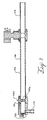
Fig. 2 is a perspective view of a preferred embodiment of the device of the present invention. -
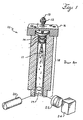
Fig. 3 is a cross-section along line A-A offigure 2 with the retractable impactor in the parallel mode. -
Fig. 4 is a cross-section along line A-A offigure 2 with the retractable in the perpendicular mode. -
Fig. 5 is an end perspective view of the retractable impactor. -
Fig. 6 is a top plan view of the retractable impactor. - With reference to
Figure 2 , a preferred embodiment of the evaporativelight scattering device 100 of the present invention is illustrated. The device comprises anebulizer 102. The nebulizer is preferably as disclosed in co-pending application serial no. 08/932,262 and is available from ALL TECH ASSOCIATES, part no. 600514. Downstream in the direction of flow from the nebulizer is atube 104. The drift tube may preferably be constructed as set forth in co-pending application serial no. 08/932,262. The drift tube has two sections, anebulizer block 106 and a mid-section 108. Thenebulizer block 106 connects thenebulizer 102 to the drift tube. Thenebulizer 102 is in flow communication with thedrift tube 104. Thedrift tube 104 further has adrain outlet 110, which is preferably located on thenebulizer block 106. The drift tube also has aretractable impactor 105, which is also preferably located on thenebulizer block 106. Theimpactor 105 preferably comprises a planar,solid section 105a mounted on apin 105b. By retractable, it is meant that theplanar section 105a may be rotated from a position where the face of the planar section is parallel to the direction of fluid flow (parallel mode) to a position in which the face of the planar section is at a 90 degree angle to the path of flow (perpendicular mode) through thedrift tube 104. When in the perpendicular mode, the planar section provides an impact surface for the nebulized mobile phase particles to strike, which leads to condensation of those particles. By directing the mobile phase against the impactor in this fashion, a portion of the mobile phase undergoes condensation and is separated from the nebulized sample particles. Moreover, because the drift tube is positioned at an angle such that the drain outlet is below the impactor relative a plane X-X through the device between the impactor and the drain outlet, condensed mobile phase is removed from the device by gravity through thedrain outlet 110. - Preferably, the
planar section 105a is tapered (seeFig. 4 ) and is constructed from TEFLON coated stainless steel. The outer edges of the planar section 105 c and generally correspond to the contour of the inner wall 104a of the drift tube. The impactor pin is preferably constructed from stainless steel. In the perpendicular mode, the impactor preferably blocks about 70% of the flow path in the plane through the drift tube in which the impactorplanar section 105a resides. In the parallel mode, the impactor preferably blocks about 18% of the flow path in the plane through the drift tube in which the impactorplanar section 105a resides. However, because the impactor is preferably tapered (seeFigure 5 ), most of the mobile phase and sample will flow past the impactor when it is in its parallel mode. The impactor is preferably rotated between the parallel and perpendicular modes by a motor (not shown), such as a direct drive solenoid motor. However, the impactor may be rotated manually if desired. Also, rotation of the impactor may be programmed by the user and driven by logic. - Alternatively, the device may be constructed such that the impactor is inserted and retracted from the fluid flow channel instead of rotated between the perpendicular and parallel modes as described above. Thus, the impactor may be inserted into the flow channel of the drift tube and positioned in the perpendicular mode and removed from the flow channel all together by appropriate means. The term "retractable" is meant to include the above described impactor that may be rotated between the perpendicular and parallel modes as well as to an impactor that may be inserted into the flow channel and positioned in the perpendicular mode and removed from the flow channel all together.
- Additionally, the shape of the impactor may be varied. The only critical aspect of the impactor is that it provide a sufficient impact surface for the nebulized mobile phase when the device is in the split flow configuration and that this impact surface may be easily removed from the path of flow for converting to the single flow configuration.
- With further reference to
Figures 2-4 , thedrift tube 104 is in flow communication with anoptics block 112. The optics block comprises alight source 114, which is preferably a laser available from COHERENT as part VLMIII-5L, and alight trap 116. The light trap is preferably an insulated block of black anodized aluminum of suitable curvature to funnel light to its end. The device further comprises a detector 118, which comprises a photo diode and amplifier available from ELECTRO-OPTICAL SYSTEMS as part no. S-050-E8. Thedrift tube 104 and optics block 112 are in flow communication with anexhaust tube 122. - In the single flow configuration, the
impactor 105 is in the parallel mode (Fig 3 ). The sample and mobile phase are introduced into thenebulizer 102 where the sample and mobile phase are nebulized. The sample and mobile phase particles are then flowed to the drift tube where the mobile phase is evaporated. The sample particles are then flowed to the optics block where the sample particles are detected. The sample particles are then flowed to theexhaust tube 122 and then to waste. - The device may be quickly and easily converted to the split flow configuration by placing the impactor in the perpendicular mode (
Fig. 4 ). In this mode, sample and mobile phase are nebulized in the nebulizer. The nebulized sample and mobile phase strike theplanar section 105a of the impactor, which removes a portion of the nebulized mobile phase (and possible a portion of the sample) from the flow stream by condensation. This condensate is flowed out of the drift tube throughdrain outlet 110. The remaining portion of the sample and mobile phase is flowed through the drift tube where the mobile phase is evaporated. The sample particles are then flowed to the optics block where the sample is detected. - In a preferred aspect of the invention, the device has four zones in which the temperature is controlled independently of the other zones. Thus, the first zone is located between the
nebulizer 102 and theimpactor 105. The second zone is located between theimpactor 105 and the optics block 112. The third zone is theoptics block 112. The fourth zone is the exhaust tube. The zones are heated by using heat tape embedded in the nebulizer block, drift tube, optics block and the exhaust tube as well known in the art. Moreover, each of these zones is connected to their own power source for independent temperature control. As those skilled in the art will appreciate, optimum temperature conditions for the particular sample and mobile phase are more easily achieved by dividing the device into four temperature zones. - According to a most preferred embodiment of the present invention, the evaporative light scattering device may have the following dimensions. The distance between the tip of the nebulizer needle to the end of the
exhaust tube 122 is 600,13 mm (23,627 inches). The distance from the tip of the nebulizer needle to theimpactor 105 is 68,89 mm (2,594 inches). Thenebulizer block 106 is 90,78 mm (3,574 inches) in length. The mid-section of thedrift tube 104 is about 330,2 mm (13 inches) in length. The length of the exhaust tube is 10,19 mm (4,388 inches). The internal diameter of thedrift tube 104 is about 22,10 mm (0,87 inches). Theimpactor 105 preferably has the following dimensions. With reference toFigs. 5 and 6 ,edges 105f are about 0,40 mm (0,016 inches) in length. The impactor has a thickness of about 2,31 mm (0,091 inches) along line 105g.Bore 105h has an internal diameter of about 71,01 mm (0,276 inches) for receiving mountingneedle 105b. Theimpactor 105 further has a width of about 14,02 mm (0,552 inches) alongline 105i. - As those skilled in the art will appreciate, modifications may be made to the foregoing embodiments without departing from the invention, which is defined by the following claims.
Claims (7)
- A device (100) for evaporative light scattering detection wherein a sample to be detected is flowed through the device, the device comprising:a nebulizer (102);a drift tube (104) in flow communication with the nebulizer (102), the drift tube (104) positioned downstream in the direction of flow from the nebulizer (102);and an optics block (112) positioned downstream in the direction of flow from the drift tube (104), wherein the optics block (112) comprises a light source (114); anda detector to detect the sample by evaporative light scattering;
characterized bya retractable impactor (105) for easy conversion between a single flow configuration and a split flow configuration positioned in the drift tube (104), and the drift tube (104) further comprising a drain outlet (110). - The device (100) of claim 1, wherein the retractable impactor (105) comprises a planar section (105a) mounted on a pin (105b) which has a perpendicular mode, where the face of said planar section (105b) is at 90° degrees angle to the path of flow, and a parallel mode where the face of said planar section (105b) is parallel to the direction of the fluid flow, and is convertable between these two modes by rotation of the retractable impactor (105).
- The device of claim 1 or 2, wherein the drift tube (104) comprises a nebulizer block (106) and a mid-section (108) for evaporating the mobile phase, the nebulizer block (106) connecting the nebulizer (102) to the mid-section (108) of the drift tube (104), the nebulizer block (106) comprising the drain outlet (110) and the retractable impactor (105).
- The device (100) of claim 3 further comprising an exhaust tube (122) positioned downstream in the direction of flow from the optics block (112).
- The device (100) of claim 4, wherein the device (100) has four temperature zones in which the temperature can be independently controlled, the first zone located between the nebulizer (102) and the retractable impactor (105), the second zone positioned between the retractable impactor (105) and said optics block (112), the third zone located at said optics block (112), and the fourth zone positioned in the exhaust tube (122).
- The device of claim 2 wherein the impactor is rotatable between the parallel mode and the perpendicular mode by a motor.
- The device of claim 6 further comprising logic for actuating the motor.
Applications Claiming Priority (2)
| Application Number | Priority Date | Filing Date | Title |
|---|---|---|---|
| US523108 | 2000-03-10 | ||
| US09/523,108 US6229605B1 (en) | 2000-03-10 | 2000-03-10 | Evaporative light scattering device |
Publications (2)
| Publication Number | Publication Date |
|---|---|
| EP1132738A1 EP1132738A1 (en) | 2001-09-12 |
| EP1132738B1 true EP1132738B1 (en) | 2010-05-05 |
Family
ID=24083689
Family Applications (1)
| Application Number | Title | Priority Date | Filing Date |
|---|---|---|---|
| EP01105606A Expired - Lifetime EP1132738B1 (en) | 2000-03-10 | 2001-03-06 | Evaporative light scattering device |
Country Status (7)
| Country | Link |
|---|---|
| US (1) | US6229605B1 (en) |
| EP (1) | EP1132738B1 (en) |
| JP (1) | JP3342867B2 (en) |
| AT (1) | ATE467119T1 (en) |
| AU (1) | AU745620B2 (en) |
| DE (1) | DE60142002D1 (en) |
| DK (1) | DK1132738T3 (en) |
Families Citing this family (24)
| Publication number | Priority date | Publication date | Assignee | Title |
|---|---|---|---|---|
| JP3642730B2 (en) * | 2000-11-29 | 2005-04-27 | 株式会社荏原製作所 | Plating apparatus and plating solution composition management method |
| US7290723B1 (en) | 2003-03-26 | 2007-11-06 | Jiang Lu | Aerosol splitter for ELSD |
| US7268881B2 (en) * | 2004-02-17 | 2007-09-11 | The Curators Of The University Of Missouri | Light scattering detector |
| DE102004009686B3 (en) * | 2004-02-27 | 2005-09-01 | Schambeck Sfd Gmbh | Evaporative light scattering detector, for use with high pressure liquid chromatography, has a rotating chamber where an aerosol has a rotary movement with the eluent passing through a drying section into the detection chamber |
| DE102004026379B4 (en) * | 2004-05-29 | 2006-11-30 | Vermögensverwaltungs-Kommanditgesellschaft Dr. Ing. Herbert Knauer & Co. GmbH & Cie. | Scattered light detector |
| WO2006083511A2 (en) | 2005-01-18 | 2006-08-10 | Waters Investments Limited | Evaporative light scattering detector |
| US8089627B2 (en) * | 2005-01-18 | 2012-01-03 | Waters Technologies Corporation | Evaporative light scattering detector |
| US7241586B2 (en) * | 2005-02-17 | 2007-07-10 | Medtronic Minimed, Inc. | Polypeptide formulations and methods for making, using and characterizing them |
| CN101755204A (en) * | 2006-03-09 | 2010-06-23 | 全技术联合公司 | Evaporative light-scattering detector |
| JP2010512514A (en) * | 2006-12-06 | 2010-04-22 | ザ・キュレイターズ・オブ・ザ・ユニバーシティ・オブ・ミズーリ | Liquid chromatography detector and flow controller therefor |
| WO2008070775A2 (en) * | 2006-12-06 | 2008-06-12 | The Curators Of The University Of Missouri | Liquid chromatography detector and flow controller therefor |
| US7847936B2 (en) * | 2007-05-15 | 2010-12-07 | Waters Technologies Corporation | Evaporative light scattering device and methods of use thereof |
| KR20130083490A (en) | 2007-12-05 | 2013-07-22 | 올테크 어소시에이츠, 인크. | Method and apparatus for analyzing samples and collecting sample fractions |
| US20110121093A1 (en) * | 2008-03-19 | 2011-05-26 | Waters Technologies Corporation | Apparatus And Methods For Making Analyte Particles |
| DE102008022347B4 (en) | 2008-04-30 | 2018-11-22 | Symrise Ag | Apparatus, use of the apparatus and method for producing a liquid flavor condensate |
| EP2113770B1 (en) | 2008-04-30 | 2012-02-01 | Symrise AG | Device and method to reduce the ethanol content of a liquid preparation |
| US20110083493A1 (en) * | 2008-06-11 | 2011-04-14 | The Curators Of The University Of Missouri | Liquid Chromatography Detector and Flow Controller Therefor |
| KR20110104004A (en) | 2008-12-10 | 2011-09-21 | 올테크 어소시에이츠, 인크. | Machine-readable tag readers for chromatography systems, fractionation collection systems for chromatography systems, and chromatography systems |
| SG172034A1 (en) * | 2008-12-10 | 2011-07-28 | Alltech Associates Inc | Components suitable for use in devices such as an evaporative light scattering detector |
| US8314934B2 (en) | 2009-09-01 | 2012-11-20 | Alltech Associates, Inc. | Methods and apparatus for analyzing samples and collecting sample fractions |
| MX370921B (en) | 2014-06-10 | 2020-01-09 | Chemi Spa | Process for the purification of l-alpha-glycerophosphorylcholine. |
| CN107132202B (en) * | 2016-12-20 | 2023-10-27 | 苏州赛德福科学仪器有限公司 | Evaporation light scattering detector |
| CN112509724B (en) * | 2021-02-03 | 2021-04-27 | 之江实验室 | Method and device for supporting optical trap particles |
| EP4109091A1 (en) | 2021-06-21 | 2022-12-28 | Büchi Labortechnik AG | Device for detecting evaporative light scattering, and analyzer comprising such a device and method for detecting evaporative light scattering |
Family Cites Families (10)
| Publication number | Priority date | Publication date | Assignee | Title |
|---|---|---|---|---|
| US4162849A (en) * | 1977-03-22 | 1979-07-31 | Bodenseewerk Perkin-Elmer & Co., Gmbh | Selected element concentration for flameless atomic absorption spectroscopic measurements |
| US4894529A (en) * | 1988-11-03 | 1990-01-16 | High Yield Technology, Inc. | Real-time particle counter for liquids with nebulizer and dryer |
| US4958529A (en) | 1989-11-22 | 1990-09-25 | Vestec Corporation | Interface for coupling liquid chromatography to solid or gas phase detectors |
| US6011259A (en) * | 1995-08-10 | 2000-01-04 | Analytica Of Branford, Inc. | Multipole ion guide ion trap mass spectrometry with MS/MSN analysis |
| US5807750A (en) | 1995-05-02 | 1998-09-15 | Air Instruments And Measurements, Inc. | Optical substance analyzer and data processor |
| FR2742863B1 (en) * | 1995-12-22 | 1998-03-06 | Instruments Sa | DEVICE AND METHOD FOR INTRODUCING A SAMPLE FOR ANALYTICAL ATOMIC SPECTROMETRY FOR THE CONCOMITANT MERCURY ANALYSIS |
| GB9618428D0 (en) * | 1996-09-04 | 1996-10-16 | Polymer Lab Ltd | ELSD diffuser |
| GB9702360D0 (en) * | 1997-02-05 | 1997-03-26 | Brocklebank Ed J | Bike alight |
| US6362880B1 (en) * | 1997-09-17 | 2002-03-26 | Alltech Associates, Inc. | Low temperature adaptor for evaporative light detection |
| US5903338A (en) * | 1998-02-11 | 1999-05-11 | Particle Measuring Systems, Inc. | Condensation nucleus counter using mixing and cooling |
-
2000
- 2000-03-10 US US09/523,108 patent/US6229605B1/en not_active Expired - Lifetime
-
2001
- 2001-03-05 AU AU24873/01A patent/AU745620B2/en not_active Ceased
- 2001-03-06 EP EP01105606A patent/EP1132738B1/en not_active Expired - Lifetime
- 2001-03-06 DE DE60142002T patent/DE60142002D1/en not_active Expired - Lifetime
- 2001-03-06 AT AT01105606T patent/ATE467119T1/en not_active IP Right Cessation
- 2001-03-06 DK DK01105606.6T patent/DK1132738T3/en active
- 2001-03-12 JP JP2001068905A patent/JP3342867B2/en not_active Expired - Fee Related
Also Published As
| Publication number | Publication date |
|---|---|
| ATE467119T1 (en) | 2010-05-15 |
| DE60142002D1 (en) | 2010-06-17 |
| AU745620B2 (en) | 2002-03-28 |
| DK1132738T3 (en) | 2010-08-02 |
| EP1132738A1 (en) | 2001-09-12 |
| JP3342867B2 (en) | 2002-11-11 |
| AU2487301A (en) | 2001-09-13 |
| JP2001296234A (en) | 2001-10-26 |
| US6229605B1 (en) | 2001-05-08 |
Similar Documents
| Publication | Publication Date | Title |
|---|---|---|
| US6229605B1 (en) | Evaporative light scattering device | |
| US6362880B1 (en) | Low temperature adaptor for evaporative light detection | |
| EP0455892B1 (en) | Monodisperse aerosol generator for use with infrared spectrometry | |
| US4958529A (en) | Interface for coupling liquid chromatography to solid or gas phase detectors | |
| US4968885A (en) | Method and apparatus for introduction of liquid effluent into mass spectrometer and other gas-phase or particle detectors | |
| US7029921B2 (en) | Apparatus for rapid measurement of aerosol bulk chemical composition | |
| CA2016129C (en) | Monodisperse aerosol generator for use with infrared spectrometry | |
| US8920658B2 (en) | Method and apparatus for desolvating flowing liquid | |
| CA2002688A1 (en) | Interface for coupling liquid chromatography to solid or gas phase detectors | |
| EP0247180A1 (en) | Method for measurement of impurities in liquids | |
| US4980057A (en) | Apparatus for mass spectrometric analysis of liquid chromatographic fractions | |
| EP1597574B1 (en) | Evaporative light scattering detector | |
| EP1856500B1 (en) | Evaporative light scattering detector | |
| Lange et al. | Reversed-phase liquid chromatography/Fourier transform infrared spectrometry using concentric flow nebulization | |
| JPS63252244A (en) | Method and device for introducing effluent to mass spectrophotometer and other gaseous phase or particle detector | |
| EP1315962B1 (en) | Analyte detection system | |
| US3462609A (en) | Radiation sensitive nuclei detector for solutions | |
| GB2240176A (en) | Introduction of affluent into mass spectrometers and other gas-phase or particle detectors | |
| Koropchak et al. | Aerosol interfacing effects on discrete sample introduction coupled with spectrometric detection | |
| CA3208257A1 (en) | An improved interface for the controlled transport of a solution or suspension mixture toward a target zone | |
| JPH04337238A (en) | mass spectrometer | |
| JPS59210357A (en) | Analyzing device coupled with liquid chromatograph-mass spectrometer |
Legal Events
| Date | Code | Title | Description |
|---|---|---|---|
| PUAI | Public reference made under article 153(3) epc to a published international application that has entered the european phase |
Free format text: ORIGINAL CODE: 0009012 |
|
| 17P | Request for examination filed |
Effective date: 20010430 |
|
| AK | Designated contracting states |
Kind code of ref document: A1 Designated state(s): AT BE CH CY DE DK ES FI FR GB GR IE IT LI LU MC NL PT SE TR |
|
| AX | Request for extension of the european patent |
Free format text: AL;LT;LV;MK;RO;SI |
|
| AKX | Designation fees paid |
Free format text: AT BE CH CY DE DK ES FI FR GB GR IE IT LI LU MC NL PT SE TR |
|
| 17Q | First examination report despatched |
Effective date: 20050617 |
|
| 17Q | First examination report despatched |
Effective date: 20050617 |
|
| GRAP | Despatch of communication of intention to grant a patent |
Free format text: ORIGINAL CODE: EPIDOSNIGR1 |
|
| GRAS | Grant fee paid |
Free format text: ORIGINAL CODE: EPIDOSNIGR3 |
|
| GRAA | (expected) grant |
Free format text: ORIGINAL CODE: 0009210 |
|
| AK | Designated contracting states |
Kind code of ref document: B1 Designated state(s): AT BE CH CY DE DK ES FI FR GB GR IE IT LI LU MC NL PT SE TR |
|
| REG | Reference to a national code |
Ref country code: GB Ref legal event code: FG4D |
|
| REG | Reference to a national code |
Ref country code: CH Ref legal event code: EP |
|
| REG | Reference to a national code |
Ref country code: IE Ref legal event code: FG4D |
|
| REF | Corresponds to: |
Ref document number: 60142002 Country of ref document: DE Date of ref document: 20100617 Kind code of ref document: P |
|
| REG | Reference to a national code |
Ref country code: DK Ref legal event code: T3 |
|
| REG | Reference to a national code |
Ref country code: NL Ref legal event code: VDEP Effective date: 20100505 |
|
| PG25 | Lapsed in a contracting state [announced via postgrant information from national office to epo] |
Ref country code: NL Free format text: LAPSE BECAUSE OF FAILURE TO SUBMIT A TRANSLATION OF THE DESCRIPTION OR TO PAY THE FEE WITHIN THE PRESCRIBED TIME-LIMIT Effective date: 20100505 Ref country code: SE Free format text: LAPSE BECAUSE OF FAILURE TO SUBMIT A TRANSLATION OF THE DESCRIPTION OR TO PAY THE FEE WITHIN THE PRESCRIBED TIME-LIMIT Effective date: 20100505 Ref country code: ES Free format text: LAPSE BECAUSE OF FAILURE TO SUBMIT A TRANSLATION OF THE DESCRIPTION OR TO PAY THE FEE WITHIN THE PRESCRIBED TIME-LIMIT Effective date: 20100816 |
|
| PG25 | Lapsed in a contracting state [announced via postgrant information from national office to epo] |
Ref country code: FI Free format text: LAPSE BECAUSE OF FAILURE TO SUBMIT A TRANSLATION OF THE DESCRIPTION OR TO PAY THE FEE WITHIN THE PRESCRIBED TIME-LIMIT Effective date: 20100505 Ref country code: AT Free format text: LAPSE BECAUSE OF FAILURE TO SUBMIT A TRANSLATION OF THE DESCRIPTION OR TO PAY THE FEE WITHIN THE PRESCRIBED TIME-LIMIT Effective date: 20100505 |
|
| PG25 | Lapsed in a contracting state [announced via postgrant information from national office to epo] |
Ref country code: CY Free format text: LAPSE BECAUSE OF NON-PAYMENT OF DUE FEES Effective date: 20100505 Ref country code: GR Free format text: LAPSE BECAUSE OF FAILURE TO SUBMIT A TRANSLATION OF THE DESCRIPTION OR TO PAY THE FEE WITHIN THE PRESCRIBED TIME-LIMIT Effective date: 20100806 |
|
| PG25 | Lapsed in a contracting state [announced via postgrant information from national office to epo] |
Ref country code: PT Free format text: LAPSE BECAUSE OF FAILURE TO SUBMIT A TRANSLATION OF THE DESCRIPTION OR TO PAY THE FEE WITHIN THE PRESCRIBED TIME-LIMIT Effective date: 20100906 |
|
| PLBE | No opposition filed within time limit |
Free format text: ORIGINAL CODE: 0009261 |
|
| STAA | Information on the status of an ep patent application or granted ep patent |
Free format text: STATUS: NO OPPOSITION FILED WITHIN TIME LIMIT |
|
| 26N | No opposition filed |
Effective date: 20110208 |
|
| REG | Reference to a national code |
Ref country code: DE Ref legal event code: R097 Ref document number: 60142002 Country of ref document: DE Effective date: 20110207 |
|
| PGRI | Patent reinstated in contracting state [announced from national office to epo] |
Ref country code: IT Effective date: 20110501 |
|
| PG25 | Lapsed in a contracting state [announced via postgrant information from national office to epo] |
Ref country code: MC Free format text: LAPSE BECAUSE OF NON-PAYMENT OF DUE FEES Effective date: 20110331 |
|
| REG | Reference to a national code |
Ref country code: CH Ref legal event code: PL |
|
| REG | Reference to a national code |
Ref country code: IE Ref legal event code: MM4A |
|
| PG25 | Lapsed in a contracting state [announced via postgrant information from national office to epo] |
Ref country code: LI Free format text: LAPSE BECAUSE OF NON-PAYMENT OF DUE FEES Effective date: 20110331 Ref country code: CH Free format text: LAPSE BECAUSE OF NON-PAYMENT OF DUE FEES Effective date: 20110331 Ref country code: IE Free format text: LAPSE BECAUSE OF NON-PAYMENT OF DUE FEES Effective date: 20110306 |
|
| PG25 | Lapsed in a contracting state [announced via postgrant information from national office to epo] |
Ref country code: LU Free format text: LAPSE BECAUSE OF NON-PAYMENT OF DUE FEES Effective date: 20110306 |
|
| PG25 | Lapsed in a contracting state [announced via postgrant information from national office to epo] |
Ref country code: TR Free format text: LAPSE BECAUSE OF FAILURE TO SUBMIT A TRANSLATION OF THE DESCRIPTION OR TO PAY THE FEE WITHIN THE PRESCRIBED TIME-LIMIT Effective date: 20100505 |
|
| REG | Reference to a national code |
Ref country code: FR Ref legal event code: PLFP Year of fee payment: 16 |
|
| PGFP | Annual fee paid to national office [announced via postgrant information from national office to epo] |
Ref country code: DK Payment date: 20160329 Year of fee payment: 16 |
|
| PGFP | Annual fee paid to national office [announced via postgrant information from national office to epo] |
Ref country code: BE Payment date: 20160328 Year of fee payment: 16 Ref country code: FR Payment date: 20160328 Year of fee payment: 16 Ref country code: GB Payment date: 20160329 Year of fee payment: 16 |
|
| PGFP | Annual fee paid to national office [announced via postgrant information from national office to epo] |
Ref country code: DE Payment date: 20160331 Year of fee payment: 16 |
|
| PGFP | Annual fee paid to national office [announced via postgrant information from national office to epo] |
Ref country code: IT Payment date: 20160323 Year of fee payment: 16 |
|
| REG | Reference to a national code |
Ref country code: DE Ref legal event code: R082 Ref document number: 60142002 Country of ref document: DE Representative=s name: GRUENECKER PATENT- UND RECHTSANWAELTE PARTG MB, DE Ref country code: DE Ref legal event code: R081 Ref document number: 60142002 Country of ref document: DE Owner name: BUECHI LABORTECHNIK AG, CH Free format text: FORMER OWNER: ALLTECH ASSOCIATES, INC., DEERFIELD, ILL, US |
|
| REG | Reference to a national code |
Ref country code: GB Ref legal event code: 732E Free format text: REGISTERED BETWEEN 20161110 AND 20161116 |
|
| REG | Reference to a national code |
Ref country code: FR Ref legal event code: CA Effective date: 20161221 Ref country code: FR Ref legal event code: TP Owner name: BUCHI LABORTECHNIK AG, CH Effective date: 20161221 |
|
| REG | Reference to a national code |
Ref country code: DE Ref legal event code: R119 Ref document number: 60142002 Country of ref document: DE |
|
| REG | Reference to a national code |
Ref country code: DK Ref legal event code: EBP Effective date: 20170331 |
|
| GBPC | Gb: european patent ceased through non-payment of renewal fee |
Effective date: 20170306 |
|
| REG | Reference to a national code |
Ref country code: FR Ref legal event code: ST Effective date: 20171130 |
|
| PG25 | Lapsed in a contracting state [announced via postgrant information from national office to epo] |
Ref country code: FR Free format text: LAPSE BECAUSE OF NON-PAYMENT OF DUE FEES Effective date: 20170331 Ref country code: DE Free format text: LAPSE BECAUSE OF NON-PAYMENT OF DUE FEES Effective date: 20171003 |
|
| PG25 | Lapsed in a contracting state [announced via postgrant information from national office to epo] |
Ref country code: GB Free format text: LAPSE BECAUSE OF NON-PAYMENT OF DUE FEES Effective date: 20170306 Ref country code: IT Free format text: LAPSE BECAUSE OF NON-PAYMENT OF DUE FEES Effective date: 20170306 |
|
| REG | Reference to a national code |
Ref country code: BE Ref legal event code: MM Effective date: 20170331 Ref country code: BE Ref legal event code: PD Owner name: BUECHI LABORTECHNIK AG; CH Free format text: DETAILS ASSIGNMENT: CHANGE OF OWNER(S), AFFECTATION / CESSION Effective date: 20161011 |
|
| PG25 | Lapsed in a contracting state [announced via postgrant information from national office to epo] |
Ref country code: DK Free format text: LAPSE BECAUSE OF NON-PAYMENT OF DUE FEES Effective date: 20170331 |
|
| PG25 | Lapsed in a contracting state [announced via postgrant information from national office to epo] |
Ref country code: BE Free format text: LAPSE BECAUSE OF NON-PAYMENT OF DUE FEES Effective date: 20170331 |