EP1132568A2 - Sealing lateral downhole - Google Patents
Sealing lateral downhole Download PDFInfo
- Publication number
- EP1132568A2 EP1132568A2 EP01301706A EP01301706A EP1132568A2 EP 1132568 A2 EP1132568 A2 EP 1132568A2 EP 01301706 A EP01301706 A EP 01301706A EP 01301706 A EP01301706 A EP 01301706A EP 1132568 A2 EP1132568 A2 EP 1132568A2
- Authority
- EP
- European Patent Office
- Prior art keywords
- sock
- leg
- housing
- casing section
- main
- Prior art date
- Legal status (The legal status is an assumption and is not a legal conclusion. Google has not performed a legal analysis and makes no representation as to the accuracy of the status listed.)
- Granted
Links
- 238000007789 sealing Methods 0.000 title claims abstract description 10
- 239000000126 substance Substances 0.000 claims abstract description 17
- 238000000034 method Methods 0.000 claims abstract description 15
- 238000006243 chemical reaction Methods 0.000 claims abstract description 7
- 239000004033 plastic Substances 0.000 claims abstract description 4
- 239000000463 material Substances 0.000 claims description 25
- 238000010438 heat treatment Methods 0.000 claims description 9
- 229920001187 thermosetting polymer Polymers 0.000 claims description 5
- 239000004952 Polyamide Substances 0.000 claims description 3
- 230000003213 activating effect Effects 0.000 claims description 3
- 239000002131 composite material Substances 0.000 claims description 3
- 239000011159 matrix material Substances 0.000 claims description 3
- 229920002647 polyamide Polymers 0.000 claims description 3
- 238000003825 pressing Methods 0.000 claims description 3
- 238000004891 communication Methods 0.000 claims description 2
- 239000011521 glass Substances 0.000 claims 1
- 239000012783 reinforcing fiber Substances 0.000 claims 1
- 230000007246 mechanism Effects 0.000 description 5
- UIIMBOGNXHQVGW-UHFFFAOYSA-M Sodium bicarbonate Chemical compound [Na+].OC([O-])=O UIIMBOGNXHQVGW-UHFFFAOYSA-M 0.000 description 2
- 239000004568 cement Substances 0.000 description 2
- 239000002253 acid Substances 0.000 description 1
- 150000007513 acids Chemical class 0.000 description 1
- PNEYBMLMFCGWSK-UHFFFAOYSA-N aluminium oxide Inorganic materials [O-2].[O-2].[O-2].[Al+3].[Al+3] PNEYBMLMFCGWSK-UHFFFAOYSA-N 0.000 description 1
- 230000015572 biosynthetic process Effects 0.000 description 1
- 238000010276 construction Methods 0.000 description 1
- 230000008602 contraction Effects 0.000 description 1
- 229910052593 corundum Inorganic materials 0.000 description 1
- 239000012530 fluid Substances 0.000 description 1
- 238000005755 formation reaction Methods 0.000 description 1
- 239000003365 glass fiber Substances 0.000 description 1
- 229910052751 metal Inorganic materials 0.000 description 1
- 239000002184 metal Substances 0.000 description 1
- 150000002739 metals Chemical class 0.000 description 1
- 238000010137 moulding (plastic) Methods 0.000 description 1
- 230000000717 retained effect Effects 0.000 description 1
- 229910000030 sodium bicarbonate Inorganic materials 0.000 description 1
- 235000017557 sodium bicarbonate Nutrition 0.000 description 1
- 229910001845 yogo sapphire Inorganic materials 0.000 description 1
Images

Classifications
-
- E—FIXED CONSTRUCTIONS
- E21—EARTH OR ROCK DRILLING; MINING
- E21B—EARTH OR ROCK DRILLING; OBTAINING OIL, GAS, WATER, SOLUBLE OR MELTABLE MATERIALS OR A SLURRY OF MINERALS FROM WELLS
- E21B41/00—Equipment or details not covered by groups E21B15/00 - E21B40/00
- E21B41/0035—Apparatus or methods for multilateral well technology, e.g. for the completion of or workover on wells with one or more lateral branches
- E21B41/0042—Apparatus or methods for multilateral well technology, e.g. for the completion of or workover on wells with one or more lateral branches characterised by sealing the junction between a lateral and a main bore
Definitions
- This invention relates to sealing a connection between a main casing section and a lateral casing section in a well.
- lateral sections also sometimes referred to as horizontal sections or deviated sections, are used to intersect formations or zones of interest that cannot easily be accessed by merely a vertical well.
- casing is placed in both. At the intersection or joint of the main or vertical section of casing with the lateral section of casing, it is necessary to provide sealing so that proper well operations may be carried out and well fluids flowed out of the well without leakage in or out of the well casing.
- Sealing at the joint or intersection presents problems, solutions to which have been proposed through the years. For example, sealing can be successfully achieved by using cements or other similar materials. However, a problem exists in keeping such a seal intact. Any slight earth movements, or pipe movements due to contraction or expansion in the casing may sever such seals. In these instances, the cement will crack, breaking the seal, and allowing leakage into or out of the casing joint, neither of which is desirable.
- the present invention solves or mitigates this problem by providing a flexible sock made of a hardenable material which can be placed at the joint so that the legs of the sock extend into the main casing section and the lateral casing section.
- the sock is inflated to an operating position and the material hardened. In this way, a single piece, uninterrupted seal is formed. Even with some casing or earth movement, the integrity of the one-piece seal is not broken.
- the invention provides an apparatus for sealing a connection between a main casing section and a lateral casing section in a well, said apparatus comprising a housing adapted for attachment to a tubing string; a sock having an upper end attached to said housing, a first leg and a second leg, said sock being made of a hardenable material; and a bent sub connected to said housing and extending through said second leg of said sock; wherein said housing and sock may be positioned in the well adjacent to an intersection of the main and lateral casing sections; said sock may be inflated and placed in an operating position in which said first leg of said sock extends into the main casing section beyond the intersection of the main and lateral casing sections and the second leg of said sock extends into the lateral casing section beyond the intersection; and said sock may be hardened in said operating position.
- the apparatus further comprises a bent sub connected to said housing and extending through said second leg of said sock for guiding said second end into
- the invention also includes a method of connecting and sealing between a main casing section and a lateral casing section in a well, said method comprising the steps of:
- the first leg of the sock has a closed end.
- the housing and the upper end of the sock are preferably sealingly engaged, and the bent sub and the second leg of the sock are also preferably sealingly engaged.
- the sock is preferably made of a thermosettable plastic material, and the apparatus may thus further comprise heating means for applying heat to the sock and thereby hardening the sock in the operating position.
- the heating means may comprise a heater connected to the housing and/or may comprise chemicals disposed in a cavity defined in the housing for providing an exothermic reaction when released from the cavity.
- the apparatus may thus comprise a rupture disc in communication with the cavity such that the rupture disc may be ruptured by applying pressure thereto, thereby releasing the chemicals from the cavity.
- step (b) may comprise inflating the sock.
- Steps (b) and (c) may be substantially simultaneous.
- Step (c) may comprise applying heat to the hardenable material.
- This step of heating may comprise releasing a volume of chemicals adjacent to the sock such that an exothermic reaction is generated and/or activating a heater positioned adjacent to the sock.
- the step of releasing the chemicals may comprise rupturing a rupture disc retaining the chemicals in a cavity defined in a housing positioned inside the sock.
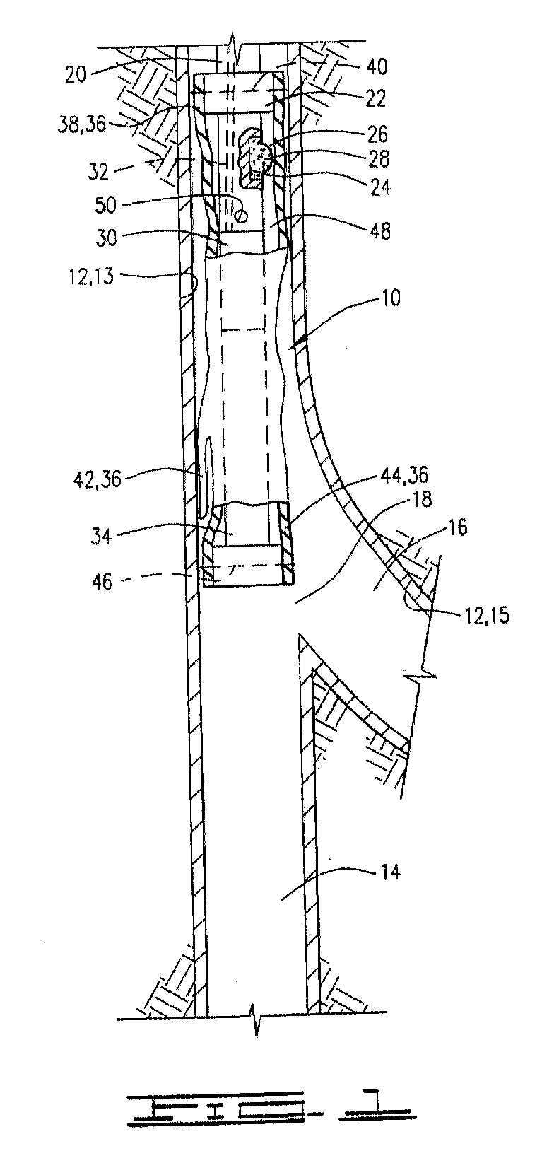
- Apparatus 10 is designed for use in a well 12.
- Well 12 has a main portion 13 with a casing section 14 therein and a lateral portion 15 extending therefrom with a casing section 16 therein, such that a joint or intersection 18 is formed between the two casing sections 14 and 16.
- Apparatus 10 is run into well 12 on a tubing string 20 of a kind known in the art.
- Tubing string 20 may be a pipe string or a coiled tubing string, or any other means of conveying a tool into a well.
- apparatus 10 is positioned adjacent to intersection 18, ready to be placed in an operating position.
- a housing 22 adapted for connection to tubing string 20 and defining a cavity 24 therein. Cavity 24 is initially closed by a rupture disc 26 so that a volume of chemicals 28 are retained in the cavity. Chemicals 28 may be contained in a plastic bag (not shown) which is ruptured when pressure is applied thereto. Chemicals 28 are selected to produce heat when released as further described herein. For example, but not by way of limitation, the reaction of acids and metals produces heat. Decomposing mixes such as: A1+F 2 O 3 ⁇ Al 2 O 3 +F produces extremely high heat. Another example is the mixing of CaC1 + baking soda.
- a heater 30 is attached to the lower end of housing 22.
- Heater 30 is of a kind known in the art and is preferably an electrical heater.
- Wiring 32 extends from heater 30 up through tubing string 20 to a power source (not shown).
- a bent sub or tool 34 of a kind known in the art is attached to the lower end of heater 30, and thus housing 22, heater 30 and bent sub 34 are all connected to each other. Bent sub 34 is adapted for guiding a portion of apparatus 10 into lateral casing section 16.
- a flexible sock 36 is disposed around housing 22, heater 30 and bent sub 34.
- Sock 36 has an upper end 38 which is disposed around the upper portion of housing 22.
- Upper end 38 of sock 36 is attached and sealed to housing 22 using retaining and releasing mechanisms known in the art such as a string 40 which lightly retains sock 36 on housing 22 when positioning apparatus 10, but which is easily broken so that the housing may be removed from the sock when desired, as further described herein.
- Other known mechanisms such as a releasable clamp could be used.
- Sock 36 also has a first leg 42 and a second leg 44.
- Second leg 44 of sock 36 is disposed around the lower portion of bent sub 34 and sealed and attached thereto by engagement of another retaining and releasing mechanism known in the art, such as string 46.
- String 46 like string 40 previously described, lightly retains second leg 44 of sock 36 on bent sub 34, but is easily broken so that the bent sub may be removed from the sock when desired, again as further described herein.
- other known mechanisms such as a releasable clamp may be used instead.
- Sock 36 is preferably made of an initially flexible material which may subsequently be hardened.
- One preferred material is a thermoset plastic material, such as a composite matrix.
- One specifically preferred composite matrix is a polyamide material reinforced with glass fibers or the like, having a curing temperature of about 550° F., but the invention is not intended to be limited to this one particular thermoset material.
- bent sub 34 While positioning, bent sub 34 is manipulated so that it extends at least partially into lateral casing section 16, as seen in FIG. 2. Thus, it will be seen that second leg 44 of sock 36 is guided into lateral casing section 16 and beyond intersection 18. First leg 42 of sock 36 is free to drape down into main casing section 14.
- annular volume 48 also ruptures rupture disc 26 so that chemicals 28 are released from housing 22.
- the release of chemicals 28 causes an exothermic reaction which applies heat to sock 36.
- sufficient heat is generated that at least partial curing of the hardenable material of sock 36 is initiated.
- sock 36 will break strings 40 and 46.
- this connection can be disconnected using a J-slot mechanism.
- Another means of disconnecting sock 36 could be the application of excessive heat at the top and bottom portions of the sock thus creating a weak and brittle connection between the sock and the component to which it is attached.
- the invention is not intended to be limited to any particular retaining or releasing means.
- additional heating may be applied by activating heater 30 to thoroughly cure the material of sock 36.
- first leg 42 of sock 36 extends beyond intersection 18 and has a closed end 52. Closed end 52 may be easily cut or drilled out later if desired.
- tubing string 20 may be raised in well 12 which will be seen to remove housing 22, heater 30 and bent sub 34 from the sock.
- Sock 36 is left in well 12 at intersection 18 to provide a reliable seal at the intersection. The seal is not easily damaged, even with some earth or piping movement.
- the material for sock 36 may be selected such that it is stable at elevated temperatures and pressures.
- sock 36 provides a smooth inner surface at intersection 18 so that subsequently run tools into lateral casing section 16 will not hang up.
- thermoset plastic material which may be hardened into the operating position
- the invention is not intended to be limited to this particular type of material.
- Other materials which may be molded into a flexible sock and subsequently hardened would also be suitable.
- thermoset plastic molding of the present invention is well adapted to carry out the ends and advantages mentioned as well as those inherent therein. While the presently preferred embodiment of an apparatus and method have been described for the purposes of this disclosure, numerous changes in the arrangement and construction of parts in the apparatus and in steps in the method may be made by those skilled in the art.
Landscapes
- Geology (AREA)
- Life Sciences & Earth Sciences (AREA)
- Engineering & Computer Science (AREA)
- Mining & Mineral Resources (AREA)
- Geochemistry & Mineralogy (AREA)
- Fluid Mechanics (AREA)
- Environmental & Geological Engineering (AREA)
- General Life Sciences & Earth Sciences (AREA)
- Physics & Mathematics (AREA)
- Heating, Cooling, Or Curing Plastics Or The Like In General (AREA)
- Treatment Of Fiber Materials (AREA)
- Moulds For Moulding Plastics Or The Like (AREA)
- Pipe Accessories (AREA)
- Devices For Use In Laboratory Experiments (AREA)
- Resistance Heating (AREA)
- Lining Or Joining Of Plastics Or The Like (AREA)
Abstract
Description
Claims (16)
- An apparatus for sealing a connection between a main casing section and a lateral casing section in a well, said apparatus comprising a housing adapted for attachment to a tubing string; a sock having an upper end attached to said housing, a first leg and a second leg, said sock being made of a hardenable material; and a bent sub connected to said housing and extending through said second leg of said sock; wherein said housing and sock may be positioned in the well adjacent to an intersection of the main and lateral casing sections; said sock may be inflated and placed in an operating position in which said first leg of said sock extends into the main casing section beyond the intersection of the main and lateral casing sections and the second leg of said sock extends into the lateral casing section beyond the intersection; and said sock may be hardened in said operating position.
- Apparatus according to claim 1, further comprising a bent sub connected to said housing and extending through said second leg of said sock for guiding said second end into the lateral casing section.
- Apparatus according to claim 2, wherein said first leg of said sock has a closed end, and/or said housing and said upper end of said sock are sealingly engaged, and/or said bent sub and said second leg of said sock are sealingly engaged.
- Apparatus according to claim 1, 2 or 3, wherein said sock is made of a thermosettable plastic material; and which apparatus further comprises heating means for applying heat to said sock to thereby harden said sock in said operating position.
- Apparatus according to claim 4, wherein said heating means comprises a heater connected to said housing, said heater preferably being an electric heater.
- Apparatus according to claim 4 or 5, wherein said housing defines a cavity therein; and said heating means comprises chemicals disposed in said cavity for providing an exothermic reaction when released therefrom.
- Apparatus according to claim 6, further comprising a rupture disc in communication with said cavity such that said rupture disc may be ruptured by applying pressure thereto, thereby releasing said chemicals from said cavity.
- Apparatus according to claim 4, 5, 6 or 7, wherein said thermoset plastic material is a composite matrix, preferably of polyamide with reinforcing fibers, preferably of glass, therein.
- Apparatus according to claim 2, further comprising means for releasing said housing and bent sub from said sock after hardening thereof, said means for releasing preferably comprising string initially attaching said upper end of said sock to said housing and said second leg of said sock to said bent sub, said string being breakable by applying pressure in said sock.
- A method of connecting and sealing between a main casing section and a lateral casing section in a well, said method comprising the steps of:(a) positioning a flexible sock made of a hardenable material adjacent to an intersection of the main and lateral casing portions, said sock comprising a first leg and a second leg;(b) placing said sock in an operating position wherein said first leg of said sock is in contact with an inner surface of the main casing section and said second leg of said sock is in contact with an inner surface of the lateral casing section; and(c) curing said hardenable material such that said sock is hardened in said operating position.
- A method according to claim 10, wherein, in step (a), said sock is made of a polyamide.
- A method according to claim 10 or 11, wherein step (b) comprises inflating said sock.
- A method of claim 10, 11 or 12, wherein step (c) comprises applying heat to said hardenable material.
- A method according to claim 13, wherein said step of heating comprises releasing a volume of chemicals adjacent to said sock such that an exothermic reaction is generated, and wherein step (a) preferably comprises positioning a housing containing said volume of chemicals inside said sock.
- A method according to claim 14, wherein said step of releasing said chemicals comprises rupturing a rupture disc retaining said chemicals in said housing.
- A method according to claim 13, wherein said step of heating comprises activating a heater positioned adjacent to said sock.
Priority Applications (1)
| Application Number | Priority Date | Filing Date | Title |
|---|---|---|---|
| DK01301706T DK1132568T3 (en) | 2000-03-10 | 2001-02-26 | Sealing of a side bore |
Applications Claiming Priority (2)
| Application Number | Priority Date | Filing Date | Title |
|---|---|---|---|
| US09/522,973 US6401815B1 (en) | 2000-03-10 | 2000-03-10 | Apparatus and method for connecting casing to lateral casing using thermoset plastic molding |
| US522973 | 2000-03-10 |
Publications (3)
| Publication Number | Publication Date |
|---|---|
| EP1132568A2 true EP1132568A2 (en) | 2001-09-12 |
| EP1132568A3 EP1132568A3 (en) | 2002-10-16 |
| EP1132568B1 EP1132568B1 (en) | 2005-01-05 |
Family
ID=24083130
Family Applications (1)
| Application Number | Title | Priority Date | Filing Date |
|---|---|---|---|
| EP01301706A Expired - Lifetime EP1132568B1 (en) | 2000-03-10 | 2001-02-26 | Sealing lateral downhole |
Country Status (7)
| Country | Link |
|---|---|
| US (1) | US6401815B1 (en) |
| EP (1) | EP1132568B1 (en) |
| BR (1) | BR0100950A (en) |
| CA (1) | CA2340508A1 (en) |
| DE (1) | DE60108186T2 (en) |
| DK (1) | DK1132568T3 (en) |
| MX (1) | MXPA01002499A (en) |
Cited By (3)
| Publication number | Priority date | Publication date | Assignee | Title |
|---|---|---|---|---|
| EP2735693A1 (en) * | 2009-03-03 | 2014-05-28 | Saudi Arabian Oil Company | Tool for locating and plugging lateral wellbores |
| EP3092434A4 (en) * | 2014-01-06 | 2017-10-25 | LMK Technologies, LLC | Method and apparatus for lining a pipe |
| US10309572B2 (en) | 2013-04-18 | 2019-06-04 | Lmk Technologies, Llc | Method and apparatus for repairing main and lateral pipes |
Families Citing this family (15)
| Publication number | Priority date | Publication date | Assignee | Title |
|---|---|---|---|---|
| US6578630B2 (en) * | 1999-12-22 | 2003-06-17 | Weatherford/Lamb, Inc. | Apparatus and methods for expanding tubulars in a wellbore |
| US7455104B2 (en) * | 2000-06-01 | 2008-11-25 | Schlumberger Technology Corporation | Expandable elements |
| AU2002210620A1 (en) * | 2000-10-06 | 2002-04-15 | Philippe Nobileau | Method and system for tubing a borehole in single diameter |
| US6652690B1 (en) * | 2001-03-06 | 2003-11-25 | Dwayne Rovira | System for providing heated fluid utilizing exothermic chemical reaction for curing resin in pipe liner/repair process |
| US7104317B2 (en) * | 2002-12-04 | 2006-09-12 | Baker Hughes Incorporated | Expandable composition tubulars |
| US6915847B2 (en) * | 2003-02-14 | 2005-07-12 | Schlumberger Technology Corporation | Testing a junction of plural bores in a well |
| US7225875B2 (en) * | 2004-02-06 | 2007-06-05 | Halliburton Energy Services, Inc. | Multi-layered wellbore junction |
| US20070095457A1 (en) * | 2005-11-02 | 2007-05-03 | The Boeing Company | Fast line maintenance repair method and system for composite structures |
| US8960292B2 (en) * | 2008-08-22 | 2015-02-24 | Halliburton Energy Services, Inc. | High rate stimulation method for deep, large bore completions |
| US8439116B2 (en) | 2009-07-24 | 2013-05-14 | Halliburton Energy Services, Inc. | Method for inducing fracture complexity in hydraulically fractured horizontal well completions |
| US9796918B2 (en) | 2013-01-30 | 2017-10-24 | Halliburton Energy Services, Inc. | Wellbore servicing fluids and methods of making and using same |
| US8631872B2 (en) * | 2009-09-24 | 2014-01-21 | Halliburton Energy Services, Inc. | Complex fracturing using a straddle packer in a horizontal wellbore |
| US9016376B2 (en) | 2012-08-06 | 2015-04-28 | Halliburton Energy Services, Inc. | Method and wellbore servicing apparatus for production completion of an oil and gas well |
| US8887803B2 (en) | 2012-04-09 | 2014-11-18 | Halliburton Energy Services, Inc. | Multi-interval wellbore treatment method |
| SE534965C2 (en) * | 2009-11-10 | 2012-02-28 | Roeranalysgruppen I Europa Ab | Method and apparatus for installing a liner in a pipe |
Family Cites Families (12)
| Publication number | Priority date | Publication date | Assignee | Title |
|---|---|---|---|---|
| US4850431A (en) | 1988-05-06 | 1989-07-25 | Halliburton Company | Method of forming a plurality of spaced substantially parallel fractures from a deviated well bore |
| WO1991018180A1 (en) * | 1990-05-18 | 1991-11-28 | Philippe Nobileau | Preform device and processes for coating and/or lining a cylindrical volume |
| DE4115563C2 (en) * | 1991-05-13 | 1994-01-20 | Linck Hans Peter | Process for lining a pipe with a branch-side branch line and device for carrying out the process |
| JP2554411B2 (en) * | 1991-05-31 | 1996-11-13 | 株式会社ゲット | Branch pipe lining material and manufacturing method thereof |
| US5318122A (en) * | 1992-08-07 | 1994-06-07 | Baker Hughes, Inc. | Method and apparatus for sealing the juncture between a vertical well and one or more horizontal wells using deformable sealing means |
| FR2704898B1 (en) * | 1993-05-03 | 1995-08-04 | Drillflex | TUBULAR STRUCTURE OF PREFORM OR MATRIX FOR TUBING A WELL. |
| US5566763A (en) | 1994-08-26 | 1996-10-22 | Halliburton Company | Decentralizing, centralizing, locating and orienting subsystems and methods for subterranean multilateral well drilling and completion |
| US5564503A (en) | 1994-08-26 | 1996-10-15 | Halliburton Company | Methods and systems for subterranean multilateral well drilling and completion |
| FR2737534B1 (en) * | 1995-08-04 | 1997-10-24 | Drillflex | DEVICE FOR COVERING A BIFURCATION OF A WELL, ESPECIALLY OIL DRILLING, OR A PIPE, AND METHOD FOR IMPLEMENTING SAID DEVICE |
| US5836357A (en) * | 1995-10-26 | 1998-11-17 | Bay Mills Ltd. | Pressure-expandable conduit liner |
| US5730224A (en) | 1996-02-29 | 1998-03-24 | Halliburton Energy Services, Inc. | Slidable access control device for subterranean lateral well drilling and completion |
| WO1998009054A1 (en) * | 1996-08-30 | 1998-03-05 | Baker Hughes Incorporated | Cement reinforced inflatable seal for a junction of a multilateral |
-
2000
- 2000-03-10 US US09/522,973 patent/US6401815B1/en not_active Expired - Fee Related
-
2001
- 2001-02-26 DE DE60108186T patent/DE60108186T2/en not_active Expired - Fee Related
- 2001-02-26 DK DK01301706T patent/DK1132568T3/en active
- 2001-02-26 EP EP01301706A patent/EP1132568B1/en not_active Expired - Lifetime
- 2001-03-09 MX MXPA01002499A patent/MXPA01002499A/en unknown
- 2001-03-09 BR BR0100950-8A patent/BR0100950A/en not_active IP Right Cessation
- 2001-03-09 CA CA002340508A patent/CA2340508A1/en not_active Abandoned
Cited By (6)
| Publication number | Priority date | Publication date | Assignee | Title |
|---|---|---|---|---|
| EP2735693A1 (en) * | 2009-03-03 | 2014-05-28 | Saudi Arabian Oil Company | Tool for locating and plugging lateral wellbores |
| EP2740883A1 (en) * | 2009-03-03 | 2014-06-11 | Saudi Arabian Oil Company | Tool for locating and plugging lateral wellbores |
| US10309572B2 (en) | 2013-04-18 | 2019-06-04 | Lmk Technologies, Llc | Method and apparatus for repairing main and lateral pipes |
| US10591102B2 (en) | 2013-04-18 | 2020-03-17 | Lmk Technologies, Llc | Method and apparatus for repairing main and lateral pipes |
| EP3092434A4 (en) * | 2014-01-06 | 2017-10-25 | LMK Technologies, LLC | Method and apparatus for lining a pipe |
| US10024481B2 (en) | 2014-01-06 | 2018-07-17 | Lmk Technologies, Llc | Method and apparatus for lining a pipe |
Also Published As
| Publication number | Publication date |
|---|---|
| US6401815B1 (en) | 2002-06-11 |
| DK1132568T3 (en) | 2005-04-11 |
| DE60108186D1 (en) | 2005-02-10 |
| EP1132568B1 (en) | 2005-01-05 |
| BR0100950A (en) | 2001-10-30 |
| MXPA01002499A (en) | 2004-05-31 |
| DE60108186T2 (en) | 2005-06-09 |
| EP1132568A3 (en) | 2002-10-16 |
| CA2340508A1 (en) | 2001-09-10 |
Similar Documents
| Publication | Publication Date | Title |
|---|---|---|
| EP1132568B1 (en) | Sealing lateral downhole | |
| US7320367B2 (en) | Annular isolators for expandable tubulars in wellbores | |
| US5833001A (en) | Sealing well casings | |
| EP0360319B1 (en) | Method for placing a body of shape memory material within a cavity | |
| EP1778947B1 (en) | Methods and systems for cementing wells that lack surface casing | |
| US4813481A (en) | Expendable flapper valve | |
| CA2547007C (en) | Swelling layer inflatable | |
| US4865127A (en) | Method and apparatus for repairing casings and the like | |
| EP2454446B1 (en) | Well tool and method for in situ introduction of a treatment fluid into an annulus in a well | |
| CN101460699B (en) | A method and apparatus for patching a well by hydroforming a tubular metal patch, and a patch for this purpose | |
| BRPI0805644B1 (en) | seal and method of reinforcing a pipe in a wellbore | |
| EP0999337A2 (en) | Remotely actuated well plug apparatus | |
| CN101720378A (en) | Apparatus and method for expanding a tubular element | |
| KR20000029292A (en) | Pipe lining method | |
| US7510010B2 (en) | System and method for cementing through a safety valve | |
| US20200277836A1 (en) | Buckle prevention ring | |
| CN101194083A (en) | annular packer | |
| EP2304306B1 (en) | Method for in-situ repair of a hole in pipe in pipe tubulars | |
| JP7005752B2 (en) | Device for internal integral insulation of welded joints in pipelines | |
| US7757769B2 (en) | Wellbore and reservoir treatment device and method | |
| CN101111661A (en) | Method of installing an expandable tubular in a wellbore | |
| MX2012010156A (en) | Super shoe swell packer. | |
| US6237689B1 (en) | Method for confirming the integrity of a seal system within a subterranean well conduit Christmas tree valve assembly | |
| CA2541318A1 (en) | Well cementing apparatus and method | |
| JP4167151B2 (en) | Injection device |
Legal Events
| Date | Code | Title | Description |
|---|---|---|---|
| PUAI | Public reference made under article 153(3) epc to a published international application that has entered the european phase |
Free format text: ORIGINAL CODE: 0009012 |
|
| AK | Designated contracting states |
Kind code of ref document: A2 Designated state(s): AT BE CH CY DE DK ES FI FR GB GR IE IT LI LU MC NL PT SE TR |
|
| AX | Request for extension of the european patent |
Free format text: AL;LT;LV;MK;RO;SI |
|
| PUAL | Search report despatched |
Free format text: ORIGINAL CODE: 0009013 |
|
| AK | Designated contracting states |
Kind code of ref document: A3 Designated state(s): AT BE CH CY DE DK ES FI FR GB GR IE IT LI LU MC NL PT SE TR |
|
| AX | Request for extension of the european patent |
Free format text: AL;LT;LV;MK;RO;SI |
|
| 17P | Request for examination filed |
Effective date: 20030124 |
|
| AKX | Designation fees paid |
Designated state(s): DE DK FR GB IT NL |
|
| GRAP | Despatch of communication of intention to grant a patent |
Free format text: ORIGINAL CODE: EPIDOSNIGR1 |
|
| GRAS | Grant fee paid |
Free format text: ORIGINAL CODE: EPIDOSNIGR3 |
|
| GRAA | (expected) grant |
Free format text: ORIGINAL CODE: 0009210 |
|
| AK | Designated contracting states |
Kind code of ref document: B1 Designated state(s): DE DK FR GB IT NL |
|
| REG | Reference to a national code |
Ref country code: GB Ref legal event code: FG4D |
|
| REG | Reference to a national code |
Ref country code: IE Ref legal event code: FG4D |
|
| REF | Corresponds to: |
Ref document number: 60108186 Country of ref document: DE Date of ref document: 20050210 Kind code of ref document: P |
|
| PGFP | Annual fee paid to national office [announced via postgrant information from national office to epo] |
Ref country code: DK Payment date: 20050214 Year of fee payment: 5 |
|
| REG | Reference to a national code |
Ref country code: DK Ref legal event code: T3 |
|
| ET | Fr: translation filed | ||
| PLBE | No opposition filed within time limit |
Free format text: ORIGINAL CODE: 0009261 |
|
| STAA | Information on the status of an ep patent application or granted ep patent |
Free format text: STATUS: NO OPPOSITION FILED WITHIN TIME LIMIT |
|
| 26N | No opposition filed |
Effective date: 20051006 |
|
| REG | Reference to a national code |
Ref country code: GB Ref legal event code: FG4D |
|
| PGFP | Annual fee paid to national office [announced via postgrant information from national office to epo] |
Ref country code: NL Payment date: 20060205 Year of fee payment: 6 |
|
| PGFP | Annual fee paid to national office [announced via postgrant information from national office to epo] |
Ref country code: FR Payment date: 20060220 Year of fee payment: 6 |
|
| PGFP | Annual fee paid to national office [announced via postgrant information from national office to epo] |
Ref country code: DE Payment date: 20060223 Year of fee payment: 6 |
|
| PGFP | Annual fee paid to national office [announced via postgrant information from national office to epo] |
Ref country code: IT Payment date: 20060228 Year of fee payment: 6 |
|
| REG | Reference to a national code |
Ref country code: DK Ref legal event code: EBP |
|
| GBPC | Gb: european patent ceased through non-payment of renewal fee |
Effective date: 20070226 |
|
| NLV4 | Nl: lapsed or anulled due to non-payment of the annual fee |
Effective date: 20070901 |
|
| REG | Reference to a national code |
Ref country code: FR Ref legal event code: ST Effective date: 20071030 |
|
| PG25 | Lapsed in a contracting state [announced via postgrant information from national office to epo] |
Ref country code: NL Free format text: LAPSE BECAUSE OF NON-PAYMENT OF DUE FEES Effective date: 20070901 Ref country code: DE Free format text: LAPSE BECAUSE OF NON-PAYMENT OF DUE FEES Effective date: 20070901 Ref country code: DK Free format text: LAPSE BECAUSE OF NON-PAYMENT OF DUE FEES Effective date: 20070228 |
|
| PG25 | Lapsed in a contracting state [announced via postgrant information from national office to epo] |
Ref country code: GB Free format text: LAPSE BECAUSE OF NON-PAYMENT OF DUE FEES Effective date: 20070226 Ref country code: FR Free format text: LAPSE BECAUSE OF NON-PAYMENT OF DUE FEES Effective date: 20070228 |
|
| PGFP | Annual fee paid to national office [announced via postgrant information from national office to epo] |
Ref country code: GB Payment date: 20060222 Year of fee payment: 6 |
|
| PG25 | Lapsed in a contracting state [announced via postgrant information from national office to epo] |
Ref country code: IT Free format text: LAPSE BECAUSE OF NON-PAYMENT OF DUE FEES Effective date: 20070226 |