EP1132504A1 - Thin film depositing process and device, ftir gas analyzer used in the thin film depositing process, and mixed gas supplying device used in the thin film depositing process - Google Patents
Thin film depositing process and device, ftir gas analyzer used in the thin film depositing process, and mixed gas supplying device used in the thin film depositing process Download PDFInfo
- Publication number
- EP1132504A1 EP1132504A1 EP20010104459 EP01104459A EP1132504A1 EP 1132504 A1 EP1132504 A1 EP 1132504A1 EP 20010104459 EP20010104459 EP 20010104459 EP 01104459 A EP01104459 A EP 01104459A EP 1132504 A1 EP1132504 A1 EP 1132504A1
- Authority
- EP
- European Patent Office
- Prior art keywords
- thin film
- organic metal
- gas
- reaction chamber
- metal gases
- Prior art date
- Legal status (The legal status is an assumption and is not a legal conclusion. Google has not performed a legal analysis and makes no representation as to the accuracy of the status listed.)
- Granted
Links
- 239000010409 thin film Substances 0.000 title claims abstract description 106
- 238000000151 deposition Methods 0.000 title claims abstract description 43
- 238000000034 method Methods 0.000 title claims abstract description 35
- 230000008569 process Effects 0.000 title claims abstract description 33
- 239000007789 gas Substances 0.000 claims abstract description 307
- 229910052751 metal Inorganic materials 0.000 claims abstract description 122
- 239000002184 metal Substances 0.000 claims abstract description 122
- 238000006243 chemical reaction Methods 0.000 claims abstract description 67
- 239000000203 mixture Substances 0.000 claims abstract description 61
- 238000005033 Fourier transform infrared spectroscopy Methods 0.000 claims abstract description 44
- 239000000758 substrate Substances 0.000 claims abstract description 29
- 238000005259 measurement Methods 0.000 claims abstract description 9
- 239000002994 raw material Substances 0.000 claims description 32
- 238000000427 thin-film deposition Methods 0.000 claims description 10
- 239000012159 carrier gas Substances 0.000 description 22
- 238000001228 spectrum Methods 0.000 description 15
- 239000007769 metal material Substances 0.000 description 10
- 239000006200 vaporizer Substances 0.000 description 9
- XKRFYHLGVUSROY-UHFFFAOYSA-N Argon Chemical compound [Ar] XKRFYHLGVUSROY-UHFFFAOYSA-N 0.000 description 8
- 239000004065 semiconductor Substances 0.000 description 8
- 239000000543 intermediate Substances 0.000 description 7
- MYMOFIZGZYHOMD-UHFFFAOYSA-N Dioxygen Chemical compound O=O MYMOFIZGZYHOMD-UHFFFAOYSA-N 0.000 description 5
- 229910001882 dioxygen Inorganic materials 0.000 description 5
- 230000008020 evaporation Effects 0.000 description 5
- 238000001704 evaporation Methods 0.000 description 5
- 229910052745 lead Inorganic materials 0.000 description 5
- 229910052786 argon Inorganic materials 0.000 description 4
- 230000008859 change Effects 0.000 description 4
- 238000010438 heat treatment Methods 0.000 description 4
- 239000000463 material Substances 0.000 description 4
- 230000009466 transformation Effects 0.000 description 4
- 229910001218 Gallium arsenide Inorganic materials 0.000 description 3
- 238000000862 absorption spectrum Methods 0.000 description 3
- 150000001875 compounds Chemical class 0.000 description 3
- -1 for example Inorganic materials 0.000 description 3
- 150000002739 metals Chemical class 0.000 description 3
- 239000000126 substance Substances 0.000 description 3
- 239000002887 superconductor Substances 0.000 description 3
- 229910015802 BaSr Inorganic materials 0.000 description 2
- VYPSYNLAJGMNEJ-UHFFFAOYSA-N Silicium dioxide Chemical compound O=[Si]=O VYPSYNLAJGMNEJ-UHFFFAOYSA-N 0.000 description 2
- 230000015572 biosynthetic process Effects 0.000 description 2
- 239000000470 constituent Substances 0.000 description 2
- 230000008021 deposition Effects 0.000 description 2
- 239000010408 film Substances 0.000 description 2
- 238000004519 manufacturing process Methods 0.000 description 2
- 238000012544 monitoring process Methods 0.000 description 2
- 239000007800 oxidant agent Substances 0.000 description 2
- 239000007787 solid Substances 0.000 description 2
- 238000004611 spectroscopical analysis Methods 0.000 description 2
- 238000011144 upstream manufacturing Methods 0.000 description 2
- 229910020279 Pb(Zr, Ti)O3 Inorganic materials 0.000 description 1
- QVGXLLKOCUKJST-UHFFFAOYSA-N atomic oxygen Chemical compound [O] QVGXLLKOCUKJST-UHFFFAOYSA-N 0.000 description 1
- 238000005229 chemical vapour deposition Methods 0.000 description 1
- 229910052681 coesite Inorganic materials 0.000 description 1
- 229910052906 cristobalite Inorganic materials 0.000 description 1
- 238000007599 discharging Methods 0.000 description 1
- 239000006185 dispersion Substances 0.000 description 1
- 239000011261 inert gas Substances 0.000 description 1
- 239000001301 oxygen Substances 0.000 description 1
- 229910052760 oxygen Inorganic materials 0.000 description 1
- 239000000377 silicon dioxide Substances 0.000 description 1
- 229910052682 stishovite Inorganic materials 0.000 description 1
- 229910052905 tridymite Inorganic materials 0.000 description 1
- 230000008016 vaporization Effects 0.000 description 1
Images



Classifications
-
- C—CHEMISTRY; METALLURGY
- C23—COATING METALLIC MATERIAL; COATING MATERIAL WITH METALLIC MATERIAL; CHEMICAL SURFACE TREATMENT; DIFFUSION TREATMENT OF METALLIC MATERIAL; COATING BY VACUUM EVAPORATION, BY SPUTTERING, BY ION IMPLANTATION OR BY CHEMICAL VAPOUR DEPOSITION, IN GENERAL; INHIBITING CORROSION OF METALLIC MATERIAL OR INCRUSTATION IN GENERAL
- C23C—COATING METALLIC MATERIAL; COATING MATERIAL WITH METALLIC MATERIAL; SURFACE TREATMENT OF METALLIC MATERIAL BY DIFFUSION INTO THE SURFACE, BY CHEMICAL CONVERSION OR SUBSTITUTION; COATING BY VACUUM EVAPORATION, BY SPUTTERING, BY ION IMPLANTATION OR BY CHEMICAL VAPOUR DEPOSITION, IN GENERAL
- C23C16/00—Chemical coating by decomposition of gaseous compounds, without leaving reaction products of surface material in the coating, i.e. chemical vapour deposition [CVD] processes
- C23C16/44—Chemical coating by decomposition of gaseous compounds, without leaving reaction products of surface material in the coating, i.e. chemical vapour deposition [CVD] processes characterised by the method of coating
- C23C16/455—Chemical coating by decomposition of gaseous compounds, without leaving reaction products of surface material in the coating, i.e. chemical vapour deposition [CVD] processes characterised by the method of coating characterised by the method used for introducing gases into reaction chamber or for modifying gas flows in reaction chamber
- C23C16/45512—Premixing before introduction in the reaction chamber
-
- C—CHEMISTRY; METALLURGY
- C23—COATING METALLIC MATERIAL; COATING MATERIAL WITH METALLIC MATERIAL; CHEMICAL SURFACE TREATMENT; DIFFUSION TREATMENT OF METALLIC MATERIAL; COATING BY VACUUM EVAPORATION, BY SPUTTERING, BY ION IMPLANTATION OR BY CHEMICAL VAPOUR DEPOSITION, IN GENERAL; INHIBITING CORROSION OF METALLIC MATERIAL OR INCRUSTATION IN GENERAL
- C23C—COATING METALLIC MATERIAL; COATING MATERIAL WITH METALLIC MATERIAL; SURFACE TREATMENT OF METALLIC MATERIAL BY DIFFUSION INTO THE SURFACE, BY CHEMICAL CONVERSION OR SUBSTITUTION; COATING BY VACUUM EVAPORATION, BY SPUTTERING, BY ION IMPLANTATION OR BY CHEMICAL VAPOUR DEPOSITION, IN GENERAL
- C23C16/00—Chemical coating by decomposition of gaseous compounds, without leaving reaction products of surface material in the coating, i.e. chemical vapour deposition [CVD] processes
- C23C16/44—Chemical coating by decomposition of gaseous compounds, without leaving reaction products of surface material in the coating, i.e. chemical vapour deposition [CVD] processes characterised by the method of coating
- C23C16/455—Chemical coating by decomposition of gaseous compounds, without leaving reaction products of surface material in the coating, i.e. chemical vapour deposition [CVD] processes characterised by the method of coating characterised by the method used for introducing gases into reaction chamber or for modifying gas flows in reaction chamber
- C23C16/45561—Gas plumbing upstream of the reaction chamber
-
- C—CHEMISTRY; METALLURGY
- C23—COATING METALLIC MATERIAL; COATING MATERIAL WITH METALLIC MATERIAL; CHEMICAL SURFACE TREATMENT; DIFFUSION TREATMENT OF METALLIC MATERIAL; COATING BY VACUUM EVAPORATION, BY SPUTTERING, BY ION IMPLANTATION OR BY CHEMICAL VAPOUR DEPOSITION, IN GENERAL; INHIBITING CORROSION OF METALLIC MATERIAL OR INCRUSTATION IN GENERAL
- C23C—COATING METALLIC MATERIAL; COATING MATERIAL WITH METALLIC MATERIAL; SURFACE TREATMENT OF METALLIC MATERIAL BY DIFFUSION INTO THE SURFACE, BY CHEMICAL CONVERSION OR SUBSTITUTION; COATING BY VACUUM EVAPORATION, BY SPUTTERING, BY ION IMPLANTATION OR BY CHEMICAL VAPOUR DEPOSITION, IN GENERAL
- C23C16/00—Chemical coating by decomposition of gaseous compounds, without leaving reaction products of surface material in the coating, i.e. chemical vapour deposition [CVD] processes
- C23C16/44—Chemical coating by decomposition of gaseous compounds, without leaving reaction products of surface material in the coating, i.e. chemical vapour deposition [CVD] processes characterised by the method of coating
- C23C16/52—Controlling or regulating the coating process
-
- C—CHEMISTRY; METALLURGY
- C30—CRYSTAL GROWTH
- C30B—SINGLE-CRYSTAL GROWTH; UNIDIRECTIONAL SOLIDIFICATION OF EUTECTIC MATERIAL OR UNIDIRECTIONAL DEMIXING OF EUTECTOID MATERIAL; REFINING BY ZONE-MELTING OF MATERIAL; PRODUCTION OF A HOMOGENEOUS POLYCRYSTALLINE MATERIAL WITH DEFINED STRUCTURE; SINGLE CRYSTALS OR HOMOGENEOUS POLYCRYSTALLINE MATERIAL WITH DEFINED STRUCTURE; AFTER-TREATMENT OF SINGLE CRYSTALS OR A HOMOGENEOUS POLYCRYSTALLINE MATERIAL WITH DEFINED STRUCTURE; APPARATUS THEREFOR
- C30B25/00—Single-crystal growth by chemical reaction of reactive gases, e.g. chemical vapour-deposition growth
- C30B25/02—Epitaxial-layer growth
- C30B25/16—Controlling or regulating
- C30B25/165—Controlling or regulating the flow of the reactive gases
Definitions
- the present invention relates to a thin film depositing process based on chemical vapor growth using, as raw materials, organic metals, for example, PZT ferroelectrics, PLZT ferroelectrics, BaSr ferroelectrics, Cu high-temperature superconductors, and compound semiconductors such as GaAs semiconductors; a device therefor; an FTIR gas analyzer (a gas analyzer based on Fourier transformation infrared ray spectrometry) used in the thin film depositing process; and a mixed gas supplying device used in the thin film depositing process.
- organic metals for example, PZT ferroelectrics, PLZT ferroelectrics, BaSr ferroelectrics, Cu high-temperature superconductors, and compound semiconductors such as GaAs semiconductors
- a device therefor an FTIR gas analyzer (a gas analyzer based on Fourier transformation infrared ray spectrometry) used in the thin film depositing process
- a mixed gas supplying device used in the thin film deposit
- the method for forming a PZT ferroelectric thin film, using the MOCVD comprises the steps of sending inert gas such as argon gas as carrier gas into raw material vaporizers containing as source materials, for example, organic metal materials Pb(C 11 H 19 O 2 ) 2 , Zr(t-OC 4 H 9 ) 4 and Ti(i-OC 3 H 7 ) 4 , respectively, (which comprise Pb, Zr and Ti, respectively, which are main constituent elements of the PZT ferroelectric thin film), so as to produce three organic metal gases which contain Pb, Zr and Ti, respectively; mixing these organic metal gases in a gas mixing chamber; adding oxygen gas as an oxidizer thereto so as to produce a mixed organic metal gas; supplying the mixed gas into a reaction chamber whose temperature is kept to an appropriate value; and growing a thin film originating from this organic metal mixed gas on the surface of a substrate (for example, Pt/SiO 2 /Si, or Pt/MgO) set up in the reaction chamber.
- composition of the PZT ferroelectric thin film formed by the MOCVD is required to be stoichiometric.
- the composition of thin films obtained by thin film depositing processes in the prior art is controlled as follows.
- the temperatures (heating temperature) of the raw material vaporizers are first set up for the respective organic metal materials, and the concentrations of the respective gases are examined from the vapor pressures of the respective organic metal materials at the set-up temperatures.
- the concentrations of the respective organic metal materials are decided so as to correspond to a stoichiometric composition.
- the temperatures of the raw material vaporizers are subjected to fine adjustment.
- the flow rates of the carrier gases for the respective organic metal materials are set up to a constant value, so as to produce three organic metal gases. In this way, a PZT ferroelectric thin film is formed on an appropriate substrate.
- the composition of the PZT ferroelectric thin film is analyzed with an analyzer such as an energy dispersion type X-ray analyzer (EDX). On the basis of the results, the temperature of the raw material vaporizer containing the organic metal material comprising an insufficient element, and the flow rates of the respective carrier gases are again adjusted. A PZT ferroelectric thin film is again formed. The composition of this thin film is analyzed in the same manner as above to check whether or not the thin film has a given stoichiometric composition. When the thin film does not have the given stoichiometric composition, the above-mentioned work is repeated.
- an analyzer such as an energy dispersion type X-ray analyzer (EDX).
- EDX energy dispersion type X-ray analyzer
- the present invention has been made in the light of the above-mentioned situations.
- An object thereof is to provide a thin film depositing process making it possible to form a thin film having a desired composition with good reproducibility and high efficiency; a device therefor; an FTIR gas analyzer used in the thin film depositing process; and a mixed gas supplying device used in the thin film depositing process.
- a thin film depositing process comprising the steps of mixing plural organic metal gases in a gas mixing chamber and supplying the mixed gas into a reaction chamber to deposit a thin film on a substrate set up in the reaction chamber, which is characterized by measuring the mixture ratio between/among the organic metal gases supplied into the gas mixing chamber with an FTIR gas analyzer fitted to the gas mixing chamber, and individually adjusting the flow rates of the organic metal gases on the basis of results of the measurement.
- a thin film depositing process comprising the steps of mixing plural organic metal gases in a gas mixing chamber and supplying the mixed gas into a reaction chamber to deposit a thin film on a substrate set up in the reaction chamber, which is characterized by measuring the mixture ratio between/among the organic metal gases supplied into the gas mixing chamber with an FTIR gas analyzer fitted to the reaction chamber, and individually adjusting the flow rates of the organic metal gases on the basis of results of the measurement.
- a thin film depositing device comprising a gas mixing chamber for mixing plural organic metal gases and a reaction chamber for depositing a thin film on a substrate, arranged at the downstream side of the gas mixing chamber, which is characterized by an FTIR gas analyzer for measuring the mixture ratio between/among the organic metal gases being fitted to the gas mixing chamber, wherein the flow rates of the organic metal gases are individually adjustable on the basis of measurement results with the FTIR gas analyzer.
- a thin film depositing device comprising a gas mixing chamber for mixing plural organic metal gases and a reaction chamber for depositing a thin film on a substrate, arranged at the downstream side of the gas mixing chamber, which is characterized by an FTIR gas analyzer for measuring the mixture ratio between/among the organic metal gases being fitted to the reaction chamber, wherein the flow rates of the organic metal gases are individually adjustable on the basis of measurement results with the FTIR gas analyzer.
- the mixture state (mixture ratio and concentration) of the plural organic metal gases used for forming the thin film can be directly monitored, which is different from the prior art. Therefore, the composition of the thin film can be more accurately analyzed for a shorter time. As a result, thin films having a desired composition can be produced with high reproducibility and efficiency.
- the mixture state of the plural organic metal gases is analyzed in the gas mixing chamber to which the organic metal gases are supplied, which is different from the case that the organic metal gases are individually analyzed; therefore, in the case that the organic metal gases react with each other to produce intermediates and multimers, the state of the mixed organic metal gas supplied to the reaction chamber can be analyzed by monitoring the intermediates and multimers.
- the composition of the thin film formed by the deposition can be accurately and easily controlled since the state of the gases supplied in-line can be grasped.
- thin films having a target composition can be obtained with high reproducibility since the temperatures of raw material vaporizers, the flow rates of carrier gases, and the temperature at the time of mixing the gases can be controlled dependently on the concentrations (state) of gases.
- the mixture state of the plural organic metal gases is analyzed in the reaction chamber to which mixed gas of the organic metal gases is supplied. Therefore, the same effects and advantages as in the inventions recited in claim 1 or 3 can be obtained. Besides, the state of the gas can be monitored under conditions nearer to actually film-deposition conditions. Dependently on the pressure inside the reaction chamber or the temperature of the substrate, the organic metal gases may decompose in the gas phase and solid contents produced at this time are taken in the thin film so that the quality of the film may deteriorate remarkably. According to the invention recited in claim 2 or 4, reaction of the production in the gas phase can be monitored.
- a FTIR gas analyzer used in a thin film depositing process comprising the steps of mixing plural organic metal gases in a gas mixing chamber and supplying the mixed gas into a reaction chamber to deposit a thin film on a substrate set up in the reaction chamber, which is characterized by an infrared ray source and an interferometer being arranged at one side of the gas mixing chamber, and an infrared ray detector for detecting infrared rays transmitted through the gas mixing chamber being arranged at the other side of the gas mixing chamber to measure the mixture ratio between/among the organic metal gases introduced to the gas mixing chamber.
- a FTIR gas analyzer used in a thin film depositing process comprising the steps of mixing plural organic metal gases in a gas mixing chamber and supplying the mixed gas into a reaction chamber to deposit a thin film on a substrate set up in the reaction chamber, which is characterized by an infrared ray source and an interferometer being arranged at one side of the reaction chamber and an infrared detector for detecting infrared beam transmitted through the reaction chamber being arranged at the other side of the reaction chamber to measure the mixture ratio between/among the organic metal gases introduced to the reaction chamber.
- the mixture state of the organic metal gases can be measured with a single FTIR gas analyzer.
- a mixed gas supplying device used in a thin film deposition process comprising the steps of mixing plural organic metal gases in a gas mixing chamber and supplying the mixed gas into a reaction chamber to deposit a thin film on a substrate set up in the reaction chamber, which is characterized in that a control signal being based on a result of the mixture ratio between/among the organic metal gases, which is measurable with an FTIR gas analyzer fitted to the gas mixing chamber, is transferred to raw material vaporizers for generating the organic metal gases individually, so as to adjust the flow rates of the organic metal gases individually.
- a mixed gas supplying device used in a thin film deposition process comprising the steps of mixing plural organic metal gases in a gas mixing chamber and supplying the mixed gas into a reaction chamber to deposit a thin film on a substrate set up in the reaction chamber, which is characterized in that a control signal being based on a result of the mixture ratio between/among the organic metal gases, which is measurable with an FTIR gas analyzer fitted to the reaction chamber, is supplyable to raw material vaporizers for generating the organic metal gases individually, so as to adjust the flow rates of the organic metal gases individually.
- the organic metal gases used for forming the thin film can be generated at respective given flow rates.
- thin films having a given composition can be formed with high reproducibility.
- Fig. 1 is a schematic view of one example of the thin film depositing device of the present invention.
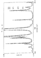
- Fig. 2 shows one example of spectra obtained when organic metal gases were separately introduced in a gas mixing chamber.
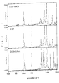
- Fig. 3 shows one example of spectra obtained when the inner temperature of the gas mixing chamber was changed.
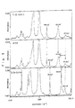
- Fig. 4 shows one example of spectra obtained when two organic metal gases were introduced in the gas mixing chamber.
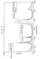
- Fig. 5 is an enlarged view of a part of the spectra shown in Fig. 4.
- Fig. 6 shows one example of spectra obtained when the temperature of the gas mixing chamber was raised in the case that two organic metal gases were simultaneously introduced in the gas mixing chamber.
- Fig. 7 is a schematic view of another example of the thin film depositing device of the present invention.
- Figs. 1-6 are related to a first embodiment of the present invention.
- Fig. 1 is a schematic view of one example of a thin film depositing device (MOCVD device) for carrying out the thin film depositing process of the present invention.
- This device is, for example, a device for forming a PZT ferroelectric thin film.
- a raw material vaporizing unit 1 has three raw material vaporizers 2-4.
- the raw material vaporizers 2-4 have containers 2a-4a, respectively, containing organic metal materials Pb(C 11 H 19 O 2 ) 2 , Zr(t-OC 4 H 9 ) 4 and Ti(i-OC 3 H 7 ) 4 , respectively, (which comprise Pb, Zr and Ti, respectively, which are main constituent elements of the PZT ferroelectric thin film); and thermostats 2b-4b for raising or keeping the temperatures of the containers 2a-4a to appropriate temperatures.
- the temperatures of the thermostats 2b-4b can be set up or controlled independently from each other.
- the containers 2a-4a have carrier gas passages 5-7 for introducing carrier gases CG 1 , CG 2 and CG 3 (each of which is, for example, argon gas), respectively; and generated gas passages 8-10 for discharging organic metal gases G 1 , G 2 and G 3 which are generated by evaporation of the organic metal materials in the raw material vaporizers 2-4 and which contain Pb, Zr and Ti, respectively, and forwarding the gases G 1 , G 2 and G 3 to respective a gas mixing chamber (described later).
- carrier gas passages 5-7 for introducing carrier gases CG 1 , CG 2 and CG 3 (each of which is, for example, argon gas), respectively; and generated gas passages 8-10 for discharging organic metal gases G 1 , G 2 and G 3 which are generated by evaporation of the organic metal materials in the raw material vaporizers 2-4 and which contain Pb, Zr and Ti, respectively, and forwarding the gases G 1 , G 2 and G 3 to respective a gas mixing chamber
- Reference number 11 indicates a control unit for controlling the flow rates of the carrier gases, arranged at the upstream side of the carrier gas passages 5-7.
- the control unit 11 is composed of three mass flow controller 12-14 arranged correspondingly to the respective carrier gas passages 5-7.
- Each of the mass controllers 12-14 is not specifically illustrated, and is composed of a gas flow rate sensor unit and a gas flow rate control valve to measure the flow rate of the actually-flowing gas (argon gas in the present embodiment) and control 1 the gas flow rates in the manner that the measured flow rates become equal to set-up values given from the outside.
- Argon gas cylinders (not illustrated) are connected to the carrier gas passages 5-7 at the upstream side to the mass flow controllers 12-14.
- Reference number 15 indicates a gas mixing chamber arranged at the downstream side of the carrier gas passages 5-7.
- the forwarded organic metal gases G 1 , G 2 and G 3 together with the forwarded carrier gases CG 1 , CG 2 and CG 3 are supplied to the gas mixing chamber 15, and then these organic metal gases G 1 , G 2 and G 3 are mixed therein.
- This gas mixing chamber 15 is made in the manner that the temperature of the chamber 15 is appropriately raised or kept with a non-illustrated heater.
- Non-illustrated windows made of an infrared ray transmissible material are made in opposite side walls of the gas mixing chamber 15.
- An infrared ray source 16 and an interferometer 17 are set up outside one of the windows so that infrared rays IR can be radiated into the gas mixing chamber 15.
- An infrared ray detector 18 such as a semiconductor detector and an arithmetic and control unit 19 for calculating the concentration of a target component to be measured by processing outputs from the detector 18 appropriately are set up outside of the other window.
- the detector 18 detects the infrared rays IR which have been transmitted through the gas mixing chamber 15.
- the gas mixing chamber 15 functions gas cells into which the organic metal gases G 1 , G 2 and G 3 are supplied as sample gases. Therefore, in the thin film depositing device of the present embodiment, a gas analyzer 20 based on Fourier transformation infrared ray spectrometry (referred as an FTIR gas analyzer in the specification) is fitted to the gas mixing chamber 15. Accordingly, the infrared rays IR are radiated to the gases supplied to the gas mixing chamber 15 through the interferometer 17. Typically, infrared detector output is accumulated and averaged, and is subjected to Fourier transformation.
- FTIR gas analyzer Fourier transformation infrared ray spectrometry
- the arithmetic and control unit 19 has a function of calculating the concentration merely, and also has a function of sending temperature control signals to a temperature control unit (not shown) of the raw material vaporizers 2-4 on the basis of the results of the calculation, and sending control signals to the three mass flow controller 12-14 of the carrier gas flow rate control unit 11.
- Reference number 21 indicates an oxygen introducing passage for adding oxygen gas as an oxidizer to the mixed organic metal gas (obtained by mixing the three organic metal gases) from the gas mixing chamber 15.
- the passage 21 is connected to a gas supply passage 23 between the gas mixing chamber 15 and a reaction chamber 22 described in the following.
- Reference number 22 indicates the reaction chamber arranged at the downstream side of the gas mixing chamber 15.
- the reaction chamber 22 is adjusted so that the inside thereof has an appropriate temperature and an appropriate pressure.
- the chamber 22 has therein a substrate holder 25 on which a substrate 24 on which a PZT ferroelectric thin film is to be deposited is put.
- the substrate holder 25 can heat the substrate 24 to a given temperature.
- An exhaust passage 26 connected to the reaction chamber 22 has a suction pump 27.
- Non-illustrated open/ shut off valves are appropriately fitted to the carrier gas passages 5-7, the generated gas passages 8-10, the oxygen gas introducing passage 21, the gas supply passage 23 and the exhaust passage 26 so that these passages can be appropriately opened or shut off.
- the temperatures of the raw material vaporizers 2-4 containing organic metal materials Pb(C 11 H 19 O 2 ) 2 , Zr(t-OC 4 H 9 ) 4 and Ti(i-OC 3 H 7 ) 4 , respectively, were set to 130 °C, 30°C and 35°C, respectively.
- the flow rates of the carrier gases CG 1 , CG 2 and CG 3 supplied to the respective raw material vaporizers 2-4 were set to 100 mL/min., 50 mL/min. and 50 mL/min., respectively.
- the pressure of the reaction chamber 22 and the temperature of the substrate 24 were set to 667 Pa and 600°C, respectively.
- the suction pump 27 is operated.
- the organic metals materials i.e., Pb(C 11 H 19 O 2 ) 2 , Zr(t-OC 4 H 9 ) 4 and Ti(i-OC 3 H 7 ) 4 are heated to given temperatures, respectively, and vaporized so as to generate the organic metal gases G 1 , G 2 and G 3 containing Pb, Zr and Ti, respectively.
- the mass flow controllers 12-14 are controlled to open the valves fitted thereto, so that the carrier gases CG 1 , CG 2 and CG 3 are supplied to the raw material vaporizers 2-4.
- the organic metal gases G 1 , G 2 and G 3 inside the raw material vaporizers 2-4 are discharged with the carrier gases CG 1 , CG 2 and CG 3 to the generated gas passages 8-10, and then introduced into the gas mixing chamber 15 so that a mixed organic metal gas is prepared.
- oxygen gas is added to this gas.
- the two gases are put into the gas mixing chamber 22.
- the substrate 24 is beforehand heated to an appropriate temperature.
- Elements from the mixed organic metal gas are deposited on the substrate 24 in the presence of the oxygen gas to form a PZT thin film.
- the process up to the present stage is the same as in any thin film depositing device of this type in the prior art.
- the FTIR gas analyzer is fitted to the gas mixing chamber 15. As described above, therefore, it is possible to monitor the state of the organic metal gases G 1 , G 2 and G 3 at the stage before they are supplied to the gas mixing chamber 22 or the state that these gases are mixed with the FTIR gas analyzer 20. This will be described hereinafter.
- Fig. 2 shows results measured with the FTIR gas analyzer 20 when the organic metal gases G 1 [originating from the evaporation of Pb(C 11 H 19 O 2 ) 2 ], G 2 [originating from the evaporation of Zr(t-OC 4 H 0 ) 4 ] and G 3 [originating from the evaporation of Ti(i-OC 3 H 7 ) 4 ] were separately introduced into the gas mixing chamber 15. From these spectra, it can be understood that the absorption spectrum of each of the organic metal gases G 1 , G 2 and G 3 has a characteristically separated peak. Therefore, from the value of the peak of the absorption spectrum, each of these gases can be quantitatively-supplied to the gas mixing chamber 15.
- Fig. 3 shows results measured with the FTIR gas analyzer 20 when the temperature of the raw material vaporizer 3 for generating, for example, the organic metal gas G 2 was gradually raised.
- This graph demonstrates that as the temperature of this vaporizer 3 is raised, the concentration of the gas becomes higher and the peak strength of the spectrum becomes larger. Therefore, it can be understood that the concentration of the gas can be monitored with the FTIR gas analyzer 20.
- the introduced amounts of the carrier gases CG 1 , CG 2 and CG 3 were increased while the temperature of the raw material vaporizer 3 was kept to a given constant value, substantially the same results were obtained.
- the organic metal gases G 1 , G 2 and G 3 which are raw materials of a PZT ferroelectric thin film, can be separately monitored. Therefore, The mixed organic metal gas can be. stably supplied to the reaction chamber 22 so that a PZT ferroelectric thin film having a stoichiometric composition can be deposited.
- the mixed organic metal can be stably supplied by feeding back control signals to the raw material vaporizer 1 or the control unit 11 for controlling the carrier gas flow rates on the basis of the results measured with the FTIR gas analyzer 20 and adjusting the heating or retaining temperature of the raw material vaporizer 2-4 or the flow rates based on the mass flow controllers 12-14 individually.
- Fig. 4 shows results measured with the FTIR gas analyzer 20 in the case that the organic metal gases G 2 [originating from Zr(t-OC 4 H 9 ) 4 ] and G 3 [originating from Ti(i-OC 3 H 7 ) 4 ] were simultaneously introduced into the gas mixing chamber 15 while the temperature inside the gas mixing chamber 15 was kept to 70°C.
- the upper and lower graphs show the spectrum of only the organic metal gas G 2 and that of only the organic metal gas G 3 , respectively.
- the middle graph shows the spectrum of the mixed G 2 and G 3 .
- the middle spectrum is different from the spectrum obtained by introducing only the organic metal gas G 2 to the gas mixing chamber 15 and the spectrum obtained by introducing only the organic metal gas G 3 thereto, That is, in the middle spectrum, peaks were lost or shifted from the upper and lower spectra, and new peaks were generated.
- Fig. 5 is an enlarged view of a part (1600-350cm -1 ) of the wavenumber range shown in Fig. 4.
- the reason of the lost or shift of the peaks and new generation of the peaks is that the two organic metal gases G 2 and G 3 reacted with each other in the gas mixing chamber 15 to produce multimers or intermediates.
- Fig. 6 shows results measured with the FTIR gas analyzer 20 in the case that the temperature of the gas mixing chamber 15 was gradually raised when the organic metal gases G 2 and G 3 were simultaneously introduced to the gas mixing chamber 15. From this graph, it can be understood that if the temperature rises at the time of mixing the organic metal gases G 2 and G 3 , the generated amounts of the multimers and the intermediates change.
- the present embodiment makes it possible to monitor the mixture state of the organic metals gases (G 2 and G 3 in the present embodiment) which are raw materials of a PZT ferroelectric thin film with the FTIR gas analyzer 20 fitted to the gas mixing chamber 15. Since the multimers and the intermediates originating from the mixing can be monitored, the mixed organic metal gas can be stably supplied to the reaction chamber 22. As a result, a PZT thin film having a stoichiometric composition can be deposited.
- the mixed organic metal can be stably supplied by feed back control signals to the raw material vaporizer 1, the control unit 11 for controlling the carrier gas flow rates or gas mixing chamber 15 on the basis of the results measured with the FTIR gas analyzer 20 and adjusting the heating or retaining temperature of the raw material vaporizer 2-4 or the flow rates based on the mass flow controllers 12-14 individually.
- the organic metal gases G 1 , G 2 and G 3 used in the formation of the PZT ferroelectric thin film are introduced and the FTIR gas analyzer 20 is fitted to the gas mixing chamber 15 for mixing theses gases.
- the mixture state (mixture ratio and concentration) of the organic metal gases G 1 , G 2 and G 3 can be directly monitored. Accordingly, the composition of the thin film can be accurately analyzed for a short time.
- the quantities to be controlled about the respective parts of the device for example, the flow rates of the carrier gases CG, the heating or retaining temperature of the raw material vaporizer 2-4 or the temperature at the time of the mixing
- the quantities to be controlled about the respective parts of the device for example, the flow rates of the carrier gases CG, the heating or retaining temperature of the raw material vaporizer 2-4 or the temperature at the time of the mixing
- PZT ferroelectric thin films having a desired composition can be formed with high reproducibility and efficency.
- the mixture state of the plural organic metal gases G 1 , G 2 and G 3 is analyzed in the gas mixing chamber 15 to which the organic metal gases G 1 , G 2 and G 3 are supplied; therefore, in the case that the organic metal gases G 1 , G 2 and G 3 react with each other to produce intermediates and multimers, the state of the mixed organic metal gas supplied to the reaction chamber 22 can be analyzed by monitoring the intermediates and multimers. This process is different from the case that the organic metal gases G 1 , G 2 and G 3 are individually analyzed.
- the composition of the PZT ferroelectric thin film formed by the deposition can be accurately and easily controlled since the state of the gas supplied in-line can be grasped.
- PZT ferroelectric thin films having a target composition can be obtained with high reproducibility since the temperatures of the raw material vaporizers 2-4, the flow rates of the carrier gases CG 1 , CG 2 and CG 3 , and the temperature at the time of mixing the gases can be controlled.
- the FTIR gas analyzer 20 is fitted to the gas mixing chamber 15 to which the plural organic metal gases G 1 , G 2 and G 3 are supplied. Therefore, the reaction of the gases G 1 , G 2 and G 3 can be easily analyzed and the composition of PZT ferroelectric thin films can be easily controlled.
- the mixture state of the plural organic metal gases G 1 , G 2 and G 3 can be analyzed only by fitting the single FTIR gas analyzer 20 to the gas mixing chamber 15.
- the plural organic metal gases G 1 , G 2 and G 3 used for forming PZT ferroelectric thin films can be generated at respective given flow rates.
- the first embodiment is suitable for forming PZT ferroelectric thin films having a desired composition with high reproducibility.
- the FTIR gas analyzer 20 for analyzing the mixture state of the plural organic metal gases G 1 , G 2 and G 3 is fitted to the gas mixing chamber 15.
- the FTIR gas analyzer 20 may be also fitted to a reaction chamber 22.
- windows (not shown) that are made of an infrared ray transmissible material are made in opposite side walls of the reaction chamber 22.
- An infrared ray source 16 and an interferometer 17 are set up outside one of the windows so that infrared rays IR can be radiated into the reaction chamber 22.
- An infrared ray detector 18 such as a semiconductor detector and an arithmetic and control unit 19 for calculating the concentration of a target component to be measured by processing outputs from the detector 18 appropriately are set up outside of the other window.
- the detector 18 detects the infrared rays 18 which have been transmitted through the reaction chamber 22. Thus, the state of the mixed organic metal gas in the reaction chamber 22 can be monitored.
- a PZT ferroelectric thin film can be formed in the same way as in the thin film depositing device according to the first embodiment.
- the mixture state of the organic metal gases G 1 , G 2 and G 3 is analyzed in the reaction chamber to which the mixed gas of the organic metal gases G 1 , G 2 and G 3 is supplied. Therefore, the same effects and advantages as in the first embodiment can be obtained. Besides, the state of the gas can be monitored under conditions nearer to actually film-deposition conditions.
- the organic metal gases G 1 , G 2 and G 3 may decompose in the gas phase and solid contents produced at this time are taken in the thin film so that the quality of the film may deteriorate remarkably.
- reaction of the production in the gas phase can be monitored.
- the arithmetic and control unit 19 is arranged in the FTIR gas analyzer 20.
- the arithmetic and control unit 19 may be arranged outside the FTIR gas analyzer 20.
- the present invention can be used not only for forming PZT ferroelectric thin films but also for forming various thin films, for example, thin films to be formed by chemical vapor growth using, for example, PLZT ferroelectrics, BaSr ferroelectrics, Cu high-temperature superconductor, and compound semiconductors such as GaAs semiconductors as raw materials.
- the mixture state (mixture ratio and concentration) of plural organic metal gases used for forming a thin film can be directly monitored, which is different from the prior art. Therefore, the composition of the thin film can be more accurately analyzed for a shorter time. As a result, thin films having a desired composition can be produced with high reproducibility and efficency.
Landscapes
- Chemical & Material Sciences (AREA)
- General Chemical & Material Sciences (AREA)
- Chemical Kinetics & Catalysis (AREA)
- Engineering & Computer Science (AREA)
- Materials Engineering (AREA)
- Metallurgy (AREA)
- Organic Chemistry (AREA)
- Mechanical Engineering (AREA)
- Crystallography & Structural Chemistry (AREA)
- Chemical Vapour Deposition (AREA)
- Investigating Or Analysing Materials By Optical Means (AREA)
Abstract
Description
- The present invention relates to a thin film depositing process based on chemical vapor growth using, as raw materials, organic metals, for example, PZT ferroelectrics, PLZT ferroelectrics, BaSr ferroelectrics, Cu high-temperature superconductors, and compound semiconductors such as GaAs semiconductors; a device therefor; an FTIR gas analyzer (a gas analyzer based on Fourier transformation infrared ray spectrometry) used in the thin film depositing process; and a mixed gas supplying device used in the thin film depositing process.
- In recent years, thin film depositing processes based on MOCVD (metal-organic chemical vapor deposition) have been used as a method for forming PZT ferroelectric thin films such as a PZT [Pb(Zr, Ti)O3] thin film. The method for forming a PZT ferroelectric thin film, using the MOCVD, comprises the steps of sending inert gas such as argon gas as carrier gas into raw material vaporizers containing as source materials, for example, organic metal materials Pb(C11H19O2)2, Zr(t-OC4H9)4 and Ti(i-OC3H7)4, respectively, (which comprise Pb, Zr and Ti, respectively, which are main constituent elements of the PZT ferroelectric thin film), so as to produce three organic metal gases which contain Pb, Zr and Ti, respectively; mixing these organic metal gases in a gas mixing chamber; adding oxygen gas as an oxidizer thereto so as to produce a mixed organic metal gas; supplying the mixed gas into a reaction chamber whose temperature is kept to an appropriate value; and growing a thin film originating from this organic metal mixed gas on the surface of a substrate (for example, Pt/SiO2/Si, or Pt/MgO) set up in the reaction chamber.
- The composition of the PZT ferroelectric thin film formed by the MOCVD is required to be stoichiometric. The composition of thin films obtained by thin film depositing processes in the prior art is controlled as follows.
- That is, the temperatures (heating temperature) of the raw material vaporizers are first set up for the respective organic metal materials, and the concentrations of the respective gases are examined from the vapor pressures of the respective organic metal materials at the set-up temperatures. The concentrations of the respective organic metal materials are decided so as to correspond to a stoichiometric composition. Thereafter, the temperatures of the raw material vaporizers are subjected to fine adjustment. In this state, the flow rates of the carrier gases for the respective organic metal materials are set up to a constant value, so as to produce three organic metal gases. In this way, a PZT ferroelectric thin film is formed on an appropriate substrate.
- The composition of the PZT ferroelectric thin film is analyzed with an analyzer such as an energy dispersion type X-ray analyzer (EDX). On the basis of the results, the temperature of the raw material vaporizer containing the organic metal material comprising an insufficient element, and the flow rates of the respective carrier gases are again adjusted. A PZT ferroelectric thin film is again formed.
The composition of this thin film is analyzed in the same manner as above to check whether or not the thin film has a given stoichiometric composition. When the thin film does not have the given stoichiometric composition, the above-mentioned work is repeated. - As described above, in conventional thin film depositing processes, a thin film is formed and subsequently the composition of this thin film is analyzed. When the analyzed composition is not a given stoichiometric composition, such work that conditions for generating organic metal gases are amended is repeated. Therefore, a problem that much time is required for obtaining a thin film having a given composition arises. By repeating the formation of a thin film, the organic metal materials are consumed and the evaporation amounts of the organic metal gases change so that the composition of the gases is out of a desired stoichiometric composition. That is, a problem that reproducibility deteriorates arises.
- The above-mentioned problems also arise in not only processes for depositing a PZT ferroelectric thin film but also processes for depositing a thin film, for example, a PLZT ferroelectric thin film, a Cu high-temperature superconductor thin film, or a compound semiconductor thin film such as a GaAs semiconductor thin film, by chemical vapor growth using an organic metal as a raw material.
- The present invention has been made in the light of the above-mentioned situations. An object thereof is to provide a thin film depositing process making it possible to form a thin film having a desired composition with good reproducibility and high efficiency; a device therefor; an FTIR gas analyzer used in the thin film depositing process; and a mixed gas supplying device used in the thin film depositing process.
- To attain the above-mentioned object, the present invention recited in
claim 1 is as follows: a thin film depositing process comprising the steps of mixing plural organic metal gases in a gas mixing chamber and supplying the mixed gas into a reaction chamber to deposit a thin film on a substrate set up in the reaction chamber, which is characterized by measuring the mixture ratio between/among the organic metal gases supplied into the gas mixing chamber with an FTIR gas analyzer fitted to the gas mixing chamber, and individually adjusting the flow rates of the organic metal gases on the basis of results of the measurement. - The present invention recited in
claim 2 is as follows: a thin film depositing process comprising the steps of mixing plural organic metal gases in a gas mixing chamber and supplying the mixed gas into a reaction chamber to deposit a thin film on a substrate set up in the reaction chamber, which is characterized by measuring the mixture ratio between/among the organic metal gases supplied into the gas mixing chamber with an FTIR gas analyzer fitted to the reaction chamber, and individually adjusting the flow rates of the organic metal gases on the basis of results of the measurement. - The present invention recited in
claim 3 is as follows: a thin film depositing device comprising a gas mixing chamber for mixing plural organic metal gases and a reaction chamber for depositing a thin film on a substrate, arranged at the downstream side of the gas mixing chamber, which is characterized by an FTIR gas analyzer for measuring the mixture ratio between/among the organic metal gases being fitted to the gas mixing chamber, wherein the flow rates of the organic metal gases are individually adjustable on the basis of measurement results with the FTIR gas analyzer. - The present invention recited in
claim 4 is as follows: a thin film depositing device comprising a gas mixing chamber for mixing plural organic metal gases and a reaction chamber for depositing a thin film on a substrate, arranged at the downstream side of the gas mixing chamber, which is characterized by an FTIR gas analyzer for measuring the mixture ratio between/among the organic metal gases being fitted to the reaction chamber, wherein the flow rates of the organic metal gases are individually adjustable on the basis of measurement results with the FTIR gas analyzer. - In all of the above-mentioned inventions, the mixture state (mixture ratio and concentration) of the plural organic metal gases used for forming the thin film can be directly monitored, which is different from the prior art. Therefore, the composition of the thin film can be more accurately analyzed for a shorter time. As a result, thin films having a desired composition can be produced with high reproducibility and efficiency.
- In the invention recited in
claim - In the inventions recited in
claim claim claim - The present invention recited in
claim 5 is as follows: a FTIR gas analyzer used in a thin film depositing process comprising the steps of mixing plural organic metal gases in a gas mixing chamber and supplying the mixed gas into a reaction chamber to deposit a thin film on a substrate set up in the reaction chamber, which is characterized by an infrared ray source and an interferometer being arranged at one side of the gas mixing chamber, and an infrared ray detector for detecting infrared rays transmitted through the gas mixing chamber being arranged at the other side of the gas mixing chamber to measure the mixture ratio between/among the organic metal gases introduced to the gas mixing chamber. - The present invention recited in
claim 6 is as follows: a FTIR gas analyzer used in a thin film depositing process comprising the steps of mixing plural organic metal gases in a gas mixing chamber and supplying the mixed gas into a reaction chamber to deposit a thin film on a substrate set up in the reaction chamber, which is characterized by an infrared ray source and an interferometer being arranged at one side of the reaction chamber and an infrared detector for detecting infrared beam transmitted through the reaction chamber being arranged at the other side of the reaction chamber to measure the mixture ratio between/among the organic metal gases introduced to the reaction chamber. - According to the invention recited in
claim - The present invention recited in
claim 7 is as follows: a mixed gas supplying device used in a thin film deposition process comprising the steps of mixing plural organic metal gases in a gas mixing chamber and supplying the mixed gas into a reaction chamber to deposit a thin film on a substrate set up in the reaction chamber, which is characterized in that a control signal being based on a result of the mixture ratio between/among the organic metal gases, which is measurable with an FTIR gas analyzer fitted to the gas mixing chamber, is transferred to raw material vaporizers for generating the organic metal gases individually, so as to adjust the flow rates of the organic metal gases individually. - The present invention recited in
claim 8 is as follows: a mixed gas supplying device used in a thin film deposition process comprising the steps of mixing plural organic metal gases in a gas mixing chamber and supplying the mixed gas into a reaction chamber to deposit a thin film on a substrate set up in the reaction chamber, which is characterized in that a control signal being based on a result of the mixture ratio between/among the organic metal gases, which is measurable with an FTIR gas analyzer fitted to the reaction chamber, is supplyable to raw material vaporizers for generating the organic metal gases individually, so as to adjust the flow rates of the organic metal gases individually. - According to the invention recited in
claim - Fig. 1 is a schematic view of one example of the thin film depositing device of the present invention.
- Fig. 2 shows one example of spectra obtained when organic metal gases were separately introduced in a gas mixing chamber.
- Fig. 3 shows one example of spectra obtained when the inner temperature of the gas mixing chamber was changed.
- Fig. 4 shows one example of spectra obtained when two organic metal gases were introduced in the gas mixing chamber.
- Fig. 5 is an enlarged view of a part of the spectra shown in Fig. 4.
- Fig. 6 shows one example of spectra obtained when the temperature of the gas mixing chamber was raised in the case that two organic metal gases were simultaneously introduced in the gas mixing chamber.
- Fig. 7 is a schematic view of another example of the thin film depositing device of the present invention.
- Referring to the drawings, embodiments of the present invention will be described. Figs. 1-6 are related to a first embodiment of the present invention. Fig. 1 is a schematic view of one example of a thin film depositing device (MOCVD device) for carrying out the thin film depositing process of the present invention. This device is, for example, a device for forming a PZT ferroelectric thin film. As illustrated in Fig. 1, a raw
material vaporizing unit 1 has three raw material vaporizers 2-4. The raw material vaporizers 2-4 havecontainers 2a-4a, respectively, containing organic metal materials Pb(C11H19 O2)2, Zr(t-OC4H9)4 and Ti(i-OC3H7)4, respectively, (which comprise Pb, Zr and Ti, respectively, which are main constituent elements of the PZT ferroelectric thin film); andthermostats 2b-4b for raising or keeping the temperatures of thecontainers 2a-4a to appropriate temperatures. The temperatures of thethermostats 2b-4b can be set up or controlled independently from each other. - The
containers 2a-4a have carrier gas passages 5-7 for introducing carrier gases CG1, CG2 and CG3 (each of which is, for example, argon gas), respectively; and generated gas passages 8-10 for discharging organic metal gases G1, G2 and G3 which are generated by evaporation of the organic metal materials in the raw material vaporizers 2-4 and which contain Pb, Zr and Ti, respectively, and forwarding the gases G1, G2 and G3 to respective a gas mixing chamber (described later). -
Reference number 11 indicates a control unit for controlling the flow rates of the carrier gases, arranged at the upstream side of the carrier gas passages 5-7. Thecontrol unit 11 is composed of three mass flow controller 12-14 arranged correspondingly to the respective carrier gas passages 5-7. Each of the mass controllers 12-14 is not specifically illustrated, and is composed of a gas flow rate sensor unit and a gas flow rate control valve to measure the flow rate of the actually-flowing gas (argon gas in the present embodiment) andcontrol 1 the gas flow rates in the manner that the measured flow rates become equal to set-up values given from the outside. Argon gas cylinders (not illustrated) are connected to the carrier gas passages 5-7 at the upstream side to the mass flow controllers 12-14. -
Reference number 15 indicates a gas mixing chamber arranged at the downstream side of the carrier gas passages 5-7. The forwarded organic metal gases G1, G2 and G3 together with the forwarded carrier gases CG1, CG2 and CG3 are supplied to thegas mixing chamber 15, and then these organic metal gases G1, G2 and G3 are mixed therein. Thisgas mixing chamber 15 is made in the manner that the temperature of thechamber 15 is appropriately raised or kept with a non-illustrated heater. - Non-illustrated windows made of an infrared ray transmissible material are made in opposite side walls of the
gas mixing chamber 15. Aninfrared ray source 16 and aninterferometer 17 are set up outside one of the windows so that infrared rays IR can be radiated into thegas mixing chamber 15. Aninfrared ray detector 18 such as a semiconductor detector and an arithmetic andcontrol unit 19 for calculating the concentration of a target component to be measured by processing outputs from thedetector 18 appropriately are set up outside of the other window. Thedetector 18 detects the infrared rays IR which have been transmitted through thegas mixing chamber 15. - In this case, the
gas mixing chamber 15 functions gas cells into which the organic metal gases G1, G2 and G3 are supplied as sample gases. Therefore, in the thin film depositing device of the present embodiment, agas analyzer 20 based on Fourier transformation infrared ray spectrometry (referred as an FTIR gas analyzer in the specification) is fitted to thegas mixing chamber 15. Accordingly, the infrared rays IR are radiated to the gases supplied to thegas mixing chamber 15 through theinterferometer 17.
Typically, infrared detector output is accumulated and averaged, and is subjected to Fourier transformation. - On the basis of the output subjected to Fourier transformation, a spectrum operation is made about the target component. In this way, the concentration and so on of the specified component contained in the gas can be measured on the basis of the absorption spectrum of the component.
- The arithmetic and
control unit 19 has a function of calculating the concentration merely, and also has a function of sending temperature control signals to a temperature control unit (not shown) of the raw material vaporizers 2-4 on the basis of the results of the calculation, and sending control signals to the three mass flow controller 12-14 of the carrier gas flowrate control unit 11. -
Reference number 21 indicates an oxygen introducing passage for adding oxygen gas as an oxidizer to the mixed organic metal gas (obtained by mixing the three organic metal gases) from thegas mixing chamber 15. Thepassage 21 is connected to agas supply passage 23 between thegas mixing chamber 15 and areaction chamber 22 described in the following. -
Reference number 22 indicates the reaction chamber arranged at the downstream side of thegas mixing chamber 15. Thereaction chamber 22 is adjusted so that the inside thereof has an appropriate temperature and an appropriate pressure. Moreover, thechamber 22 has therein asubstrate holder 25 on which asubstrate 24 on which a PZT ferroelectric thin film is to be deposited is put. Thesubstrate holder 25 can heat thesubstrate 24 to a given temperature. Anexhaust passage 26 connected to thereaction chamber 22 has asuction pump 27. - Non-illustrated open/ shut off valves are appropriately fitted to the carrier gas passages 5-7, the generated gas passages 8-10, the oxygen
gas introducing passage 21, thegas supply passage 23 and theexhaust passage 26 so that these passages can be appropriately opened or shut off. - In order to form a PZT ferroelectric thin film on the
substrate 24 in the thin film depositing device having the e above-mentioned structure, for example, the following conditions were set. That is, the temperatures of the raw material vaporizers 2-4 containing organic metal materials Pb(C11H19O2)2, Zr(t-OC4H9)4 and Ti(i-OC3H7)4, respectively, were set to 130 °C, 30°C and 35°C, respectively. The flow rates of the carrier gases CG1, CG2 and CG3 supplied to the respective raw material vaporizers 2-4 were set to 100 mL/min., 50 mL/min. and 50 mL/min., respectively. The pressure of thereaction chamber 22 and the temperature of thesubstrate 24 were set to 667 Pa and 600°C, respectively. - The
suction pump 27 is operated. In the three raw material vaporizers 2-4, the organic metals materials, i.e., Pb(C11H19O2)2, Zr(t-OC4H9)4 and Ti(i-OC3H7)4 are heated to given temperatures, respectively, and vaporized so as to generate the organic metal gases G1, G2 and G3 containing Pb, Zr and Ti, respectively. - In this state, the mass flow controllers 12-14 are controlled to open the valves fitted thereto, so that the carrier gases CG1, CG2 and CG3 are supplied to the raw material vaporizers 2-4. The organic metal gases G1, G2 and G3 inside the raw material vaporizers 2-4 are discharged with the carrier gases CG1, CG2 and CG3 to the generated gas passages 8-10, and then introduced into the
gas mixing chamber 15 so that a mixed organic metal gas is prepared. Before the mixed organic metal gas is put in thegas mixing chamber 22, oxygen gas is added to this gas. The two gases are put into thegas mixing chamber 22. In thegas mixing chamber 22, thesubstrate 24 is beforehand heated to an appropriate temperature. Elements from the mixed organic metal gas are deposited on thesubstrate 24 in the presence of the oxygen gas to form a PZT thin film. The process up to the present stage is the same as in any thin film depositing device of this type in the prior art. In the present embodiment, the FTIR gas analyzer is fitted to thegas mixing chamber 15. As described above, therefore, it is possible to monitor the state of the organic metal gases G1, G2 and G3 at the stage before they are supplied to thegas mixing chamber 22 or the state that these gases are mixed with theFTIR gas analyzer 20. This will be described hereinafter. - Fig. 2 shows results measured with the
FTIR gas analyzer 20 when the organic metal gases G1 [originating from the evaporation of Pb(C11H19O2)2], G2[originating from the evaporation of Zr(t-OC4H0)4] and G3[originating from the evaporation of Ti(i-OC3H7)4] were separately introduced into thegas mixing chamber 15. From these spectra, it can be understood that the absorption spectrum of each of the organic metal gases G1, G2 and G3 has a characteristically separated peak. Therefore, from the value of the peak of the absorption spectrum, each of these gases can be quantitatively-supplied to thegas mixing chamber 15. - Fig. 3 shows results measured with the
FTIR gas analyzer 20 when the temperature of theraw material vaporizer 3 for generating, for example, the organic metal gas G2 was gradually raised. This graph demonstrates that as the temperature of thisvaporizer 3 is raised, the concentration of the gas becomes higher and the peak strength of the spectrum becomes larger. Therefore, it can be understood that the concentration of the gas can be monitored with theFTIR gas analyzer 20. In the case that the introduced amounts of the carrier gases CG1, CG2 and CG3 were increased while the temperature of theraw material vaporizer 3 was kept to a given constant value, substantially the same results were obtained. - As described above, in the present embodiment, the organic metal gases G1, G2 and G3, which are raw materials of a PZT ferroelectric thin film, can be separately monitored. Therefore, The mixed organic metal gas can be. stably supplied to the
reaction chamber 22 so that a PZT ferroelectric thin film having a stoichiometric composition can be deposited. This is because even if the amounts of the organic metal gas G1, G2 and G3 change in the middle of the film-deposition, the mixed organic metal can be stably supplied by feeding back control signals to theraw material vaporizer 1 or thecontrol unit 11 for controlling the carrier gas flow rates on the basis of the results measured with theFTIR gas analyzer 20 and adjusting the heating or retaining temperature of the raw material vaporizer 2-4 or the flow rates based on the mass flow controllers 12-14 individually. - Fig. 4 shows results measured with the
FTIR gas analyzer 20 in the case that the organic metal gases G2 [originating from Zr(t-OC4H9)4] and G3 [originating from Ti(i-OC3H7)4] were simultaneously introduced into thegas mixing chamber 15 while the temperature inside thegas mixing chamber 15 was kept to 70°C. In Fig. 4, the upper and lower graphs show the spectrum of only the organic metal gas G2 and that of only the organic metal gas G3, respectively. The middle graph shows the spectrum of the mixed G2 and G3. The middle spectrum is different from the spectrum obtained by introducing only the organic metal gas G2 to thegas mixing chamber 15 and the spectrum obtained by introducing only the organic metal gas G3 thereto, That is, in the middle spectrum, peaks were lost or shifted from the upper and lower spectra, and new peaks were generated.
This fact can be more clearly understood from Fig. 5, which is an enlarged view of a part (1600-350cm -1) of the wavenumber range shown in Fig. 4. - As illustrated in Figs. 4 and 5, the reason of the lost or shift of the peaks and new generation of the peaks is that the two organic metal gases G2 and G3 reacted with each other in the
gas mixing chamber 15 to produce multimers or intermediates. - Fig. 6 shows results measured with the
FTIR gas analyzer 20 in the case that the temperature of thegas mixing chamber 15 was gradually raised when the organic metal gases G2 and G3 were simultaneously introduced to thegas mixing chamber 15. From this graph, it can be understood that if the temperature rises at the time of mixing the organic metal gases G2 and G3, the generated amounts of the multimers and the intermediates change. - As described above, the present embodiment makes it possible to monitor the mixture state of the organic metals gases (G2 and G3 in the present embodiment) which are raw materials of a PZT ferroelectric thin film with the
FTIR gas analyzer 20 fitted to thegas mixing chamber 15. Since the multimers and the intermediates originating from the mixing can be monitored, the mixed organic metal gas can be stably supplied to thereaction chamber 22. As a result, a PZT thin film having a stoichiometric composition can be deposited. This is because even if the amounts of the organic metal gas G1, G2 and G3 change in the middle of the film-deposition, the mixed organic metal can be stably supplied by feed back control signals to theraw material vaporizer 1, thecontrol unit 11 for controlling the carrier gas flow rates orgas mixing chamber 15 on the basis of the results measured with theFTIR gas analyzer 20 and adjusting the heating or retaining temperature of the raw material vaporizer 2-4 or the flow rates based on the mass flow controllers 12-14 individually. - In the first embodiment, the organic metal gases G1, G2 and G3 used in the formation of the PZT ferroelectric thin film are introduced and the
FTIR gas analyzer 20 is fitted to thegas mixing chamber 15 for mixing theses gases. - Therefore, the mixture state (mixture ratio and concentration) of the organic metal gases G1, G2 and G3 can be directly monitored. Accordingly, the composition of the thin film can be accurately analyzed for a short time. On the basis of the results measured with the
FTIR gas analyzer 20, the quantities to be controlled about the respective parts of the device (for example, the flow rates of the carrier gases CG, the heating or retaining temperature of the raw material vaporizer 2-4 or the temperature at the time of the mixing) can be individually adjusted. Therefore, PZT ferroelectric thin films having a desired composition can be formed with high reproducibility and efficency. - That is, in the above-mentioned embodiment, the mixture state of the plural organic metal gases G1, G2 and G 3 is analyzed in the
gas mixing chamber 15 to which the organic metal gases G1, G2 and G3 are supplied; therefore, in the case that the organic metal gases G1, G2 and G3 react with each other to produce intermediates and multimers, the state of the mixed organic metal gas supplied to thereaction chamber 22 can be analyzed by monitoring the intermediates and multimers. This process is different from the case that the organic metal gases G1, G2 and G3 are individually analyzed. In the present embodiment, the composition of the PZT ferroelectric thin film formed by the deposition can be accurately and easily controlled since the state of the gas supplied in-line can be grasped. In other words, PZT ferroelectric thin films having a target composition can be obtained with high reproducibility since the temperatures of the raw material vaporizers 2-4, the flow rates of the carrier gases CG1, CG2 and CG3, and the temperature at the time of mixing the gases can be controlled. - In the above-mentioned first embodiment, the
FTIR gas analyzer 20 is fitted to thegas mixing chamber 15 to which the plural organic metal gases G1, G2 and G3 are supplied. Therefore, the reaction of the gases G1, G2 and G3 can be easily analyzed and the composition of PZT ferroelectric thin films can be easily controlled. - In the first embodiment, the mixture state of the plural organic metal gases G1, G2 and G3 can be analyzed only by fitting the single
FTIR gas analyzer 20 to thegas mixing chamber 15. - In the first embodiment, the plural organic metal gases G1, G2 and G3 used for forming PZT ferroelectric thin films can be generated at respective given flow rates. Thus, the first embodiment is suitable for forming PZT ferroelectric thin films having a desired composition with high reproducibility.
- In the first embodiment, the
FTIR gas analyzer 20 for analyzing the mixture state of the plural organic metal gases G1, G2 and G3 is fitted to thegas mixing chamber 15. However, as illustrated in Fig. 7, theFTIR gas analyzer 20 may be also fitted to areaction chamber 22. In the present second embodiment, windows (not shown) that are made of an infrared ray transmissible material are made in opposite side walls of thereaction chamber 22. Aninfrared ray source 16 and aninterferometer 17 are set up outside one of the windows so that infrared rays IR can be radiated into thereaction chamber 22. Aninfrared ray detector 18 such as a semiconductor detector and an arithmetic andcontrol unit 19 for calculating the concentration of a target component to be measured by processing outputs from thedetector 18 appropriately are set up outside of the other window. Thedetector 18 detects theinfrared rays 18 which have been transmitted through thereaction chamber 22. Thus, the state of the mixed organic metal gas in thereaction chamber 22 can be monitored. - In the thin film depositing device according to the second embodiment, a PZT ferroelectric thin film can be formed in the same way as in the thin film depositing device according to the first embodiment. In the second embodiment, the mixture state of the organic metal gases G1, G2 and G3 is analyzed in the reaction chamber to which the mixed gas of the organic metal gases G1, G2 and G3 is supplied. Therefore, the same effects and advantages as in the first embodiment can be obtained. Besides, the state of the gas can be monitored under conditions nearer to actually film-deposition conditions. Incidentally, dependently on the pressure inside the
reaction chamber 22 or the temperature of thesubstrate 24, the organic metal gases G1, G2 and G3 may decompose in the gas phase and solid contents produced at this time are taken in the thin film so that the quality of the film may deteriorate remarkably. According to the second embodiment, reaction of the production in the gas phase can be monitored. - In both of the above-mentioned embodiments, the arithmetic and
control unit 19 is arranged in theFTIR gas analyzer 20. However, the arithmetic andcontrol unit 19 may be arranged outside theFTIR gas analyzer 20. - The present invention can be used not only for forming PZT ferroelectric thin films but also for forming various thin films, for example, thin films to be formed by chemical vapor growth using, for example, PLZT ferroelectrics, BaSr ferroelectrics, Cu high-temperature superconductor, and compound semiconductors such as GaAs semiconductors as raw materials.
- According to the present invention, the mixture state (mixture ratio and concentration) of plural organic metal gases used for forming a thin film can be directly monitored, which is different from the prior art. Therefore, the composition of the thin film can be more accurately analyzed for a shorter time. As a result, thin films having a desired composition can be produced with high reproducibility and efficency.
Claims (8)
- A thin film deposition process comprising the steps of mixing plural organic metal gases in a gas mixing chamber (15) and supplying the mixed gas into a reaction chamber (22) to deposit a thin film on a substrate (24) set up in the reaction chamber (22), characterized by measuring the mixture ratio between/among the organic metal gases supplied into the gas mixing chamber (15) with an FTIR gas analyzer (20) fitted to the gas mixing chamber (15), and individually adjusting the flow rates of the organic metal gases on the basis of results of the measurement.
- A thin film deposition process comprising the steps of mixing plural organic metal gases in a gas mixing chamber (15) and supplying the mixed gas into a reaction chamber (22) to deposit a thin film on a substrate (24) set up in the reaction chamber (22), characterized by measuring the mixture ratio between/among the organic metal gases supplied into the gas mixing chamber (15) with an FTIR gas analyzer (20) fitted to the reaction chamber (22), and individually adjusting the flow rates of the organic metal gases on the basis of results of the measurement.
- A thin film deposition device comprising a gas mixing chamber (15) for mixing plural organic metal gases and a reaction chamber (22) for depositing a thin film on a substrate (24), arranged at the downstream side of the gas mixing chamber (15), characterized by an FTIR gas analyzer (20) for measuring the mixture ratio between/among the organic metal gases being fitted to the gas mixing chamber (15), wherein the flow rates of the organic metal gases are individually adjustable on the basis of measurement results with the FTIR gas analyzer (20).
- A thin film deposition device comprising a gas mixing chamber (15) for mixing plural organic metal gases and a reaction chamber (22) for depositing a thin film on a substrate (24), arranged at the downstream side of the gas mixing chamber (15), characterized by an FTIR gas analyzer (20) for measuring the mixture ratio between/among the organic metal gases being fitted to the reaction chamber (22), wherein the flow rates of the organic metal gases are individually adjustable on the basis of measurement results with the FTIR gas analyzer (20).
- A FTIR gas analyzer (20) used in a thin film deposition process comprising the steps of mixing plural organic metal gases in a gas mixing chamber (15) and supplying the mixed gas into a reaction chamber (22) to deposit a thin film on a substrate (24) set up in the reaction chamber (22), characterized by an infrared light source (16) and an interferometer (17) being arranged at one side of the gas mixing chamber (15), and an infrared detector (18) for detecting infrared beam transmitted through the gas mixing chamber (15) being arranged at the other side of the gas mixing chamber (15) to measure the mixture ratio between/ among the organic metal gases introduced to the gas mixing chamber (15).
- A FTIR gas analyzer (20) used in a thin film deposition process comprising the steps of mixing plural organic metal gases in a gas mixing chamber (15) and supplying the mixed gas into a reaction chamber (22) to deposit a thin film on a substrate(24) set up in the reaction chamber (22),
characterized by an infrared light source (16) and an interferometer (17) being arranged at one side of the reaction chamber (22) and an infrared detector (18) for detecting infrared beam transmitted through the reaction chamber (22) being arranged at the other side of the reaction chamber (22) to measure the mixture ratio between/among the organic metal gases introduced to the reaction chamber (22). - A mixed gas supplying device used in a thin film deposition process comprising the steps of mixing plural organic metal gases in a gas mixing chamber (15) and supplying the mixed gas into a reaction chamber (22) to deposit a thin film on a substrate (24) set up in the reaction chamber (22), characterized in that a control signal being based on a result of the mixture ratio between/among the organic metal gases, which is measurable with an FTIR gas analyzer (20) fitted to the gas mixing chamber (15), is supplyable to raw material vaporizers (2, 3, 4) for generating the organic metal gases individually, so as to adjust the flow rates of the organic metal gases individually.
- A mixed gas supplying device used in a thin film deposition process comprising the steps of mixing plural organic metal gases in a gas mixing chamber (15) and supplying the mixed gas into a reaction chamber (22) to deposit a thin film on a substrate (24) set up in the reaction chamber (22), characterized in that a control signal being based on a result of the mixture ratio between/ among the organic metal gases, which is measurable with an FTIR gas analyzer (20) fitted to the reaction chamber (22), is supplyable to raw material vaporizers(2, 3, 4) for generating the organic metal gases individually, so as to adjust the flow rates of the organic metal gases individually.
Applications Claiming Priority (2)
| Application Number | Priority Date | Filing Date | Title |
|---|---|---|---|
| JP2000051823A JP3905678B2 (en) | 2000-02-28 | 2000-02-28 | Thin film deposition method and apparatus, FTIR gas analyzer used for thin film deposition method, and mixed gas supply apparatus used for thin film deposition method |
| JP2000051823 | 2000-02-28 |
Publications (2)
| Publication Number | Publication Date |
|---|---|
| EP1132504A1 true EP1132504A1 (en) | 2001-09-12 |
| EP1132504B1 EP1132504B1 (en) | 2007-06-13 |
Family
ID=18573427
Family Applications (1)
| Application Number | Title | Priority Date | Filing Date |
|---|---|---|---|
| EP20010104459 Expired - Lifetime EP1132504B1 (en) | 2000-02-28 | 2001-02-28 | Thin film depositing process using an FTIR gas analyzer and a mixed gas supplying device |
Country Status (4)
| Country | Link |
|---|---|
| US (1) | US7485189B2 (en) |
| EP (1) | EP1132504B1 (en) |
| JP (1) | JP3905678B2 (en) |
| DE (1) | DE60128846T2 (en) |
Cited By (2)
| Publication number | Priority date | Publication date | Assignee | Title |
|---|---|---|---|---|
| WO2011101361A1 (en) | 2010-02-19 | 2011-08-25 | Aixtron Se | Gas mixer for vapor deposition |
| CN102492939A (en) * | 2011-12-29 | 2012-06-13 | 中国科学院半导体研究所 | Atomic layer deposition apparatus integrated with Fourier transform infrared in-situ monitoring system |
Families Citing this family (29)
| Publication number | Priority date | Publication date | Assignee | Title |
|---|---|---|---|---|
| JP2004111761A (en) * | 2002-09-20 | 2004-04-08 | Japan Pionics Co Ltd | Vapor phase growth method |
| US7628861B2 (en) * | 2004-12-17 | 2009-12-08 | Mks Instruments, Inc. | Pulsed mass flow delivery system and method |
| US7628860B2 (en) * | 2004-04-12 | 2009-12-08 | Mks Instruments, Inc. | Pulsed mass flow delivery system and method |
| US20060130755A1 (en) * | 2004-12-17 | 2006-06-22 | Clark William R | Pulsed mass flow measurement system and method |
| KR100731164B1 (en) * | 2005-05-19 | 2007-06-20 | 주식회사 피에조닉스 | Apparatus of chemical vapor deposition with a shower head and method therof |
| US7883745B2 (en) * | 2007-07-30 | 2011-02-08 | Micron Technology, Inc. | Chemical vaporizer for material deposition systems and associated methods |
| KR101227446B1 (en) * | 2007-07-31 | 2013-01-29 | 삼성전자주식회사 | Method of forming a ferro-electric layer and method of manufacturing a ferro-electric capacitor |
| DE102007038278B4 (en) * | 2007-08-08 | 2013-09-12 | Fraunhofer-Gesellschaft zur Förderung der angewandten Forschung e.V. | Mass transport and event control in systems with piezoelectrically activated droplet emission and combinations of carrier matrix and dosing agent |
| US8105954B2 (en) * | 2008-10-20 | 2012-01-31 | aiwan Semiconductor Manufacturing Company, Ltd. | System and method of vapor deposition |
| TW201122148A (en) * | 2009-12-24 | 2011-07-01 | Hon Hai Prec Ind Co Ltd | Chemical vapor deposition device |
| JP5395102B2 (en) * | 2011-02-28 | 2014-01-22 | 株式会社豊田中央研究所 | Vapor growth equipment |
| WO2013126323A1 (en) * | 2012-02-23 | 2013-08-29 | Applied Materials, Inc. | Method and apparatus for precursor delivery |
| JP5895712B2 (en) * | 2012-05-31 | 2016-03-30 | 東京エレクトロン株式会社 | Source gas supply apparatus, film forming apparatus, source gas supply method, and storage medium |
| TW201443984A (en) * | 2013-02-05 | 2014-11-16 | 日立國際電氣股份有限公司 | Cleaning method, method of manufacturing semiconductor device, substrate processing apparatus, recording medium, and cleaning end determination method |
| KR20160040509A (en) * | 2013-06-11 | 2016-04-14 | 유니버시티 오브 휴스턴 | Fixed and portable coating apparatuses and methods |
| US10443127B2 (en) * | 2013-11-05 | 2019-10-15 | Taiwan Semiconductor Manufacturing Company Limited | System and method for supplying a precursor for an atomic layer deposition (ALD) process |
| JP2016134569A (en) * | 2015-01-21 | 2016-07-25 | 株式会社東芝 | Semiconductor manufacturing equipment |
| WO2017031257A2 (en) * | 2015-08-17 | 2017-02-23 | Ichor Systems, Inc. | Fluid control system |
| US10822699B2 (en) | 2017-12-29 | 2020-11-03 | Varian Semiconductor Equipment Associates, Inc. | Techniques for controlling precursors in chemical deposition processes |
| CN110016657B (en) * | 2018-01-08 | 2020-06-19 | 北京北方华创微电子装备有限公司 | Flow control method and device and reaction chamber |
| JP7094172B2 (en) * | 2018-07-20 | 2022-07-01 | 東京エレクトロン株式会社 | Film forming equipment, raw material supply equipment and film forming method |
| JP7281285B2 (en) * | 2019-01-28 | 2023-05-25 | 株式会社堀場エステック | DENSITY CONTROLLER, ZERO POINT ADJUSTMENT METHOD, AND PROGRAM FOR DENSITY CONTROLLER |
| JP7546384B2 (en) * | 2020-06-17 | 2024-09-06 | 東京エレクトロン株式会社 | Film forming method and film forming apparatus |
| WO2022045629A1 (en) * | 2020-08-25 | 2022-03-03 | 주성엔지니어링(주) | Substrate treatment apparatus |
| TWI792161B (en) * | 2021-01-26 | 2023-02-11 | 富蘭登科技股份有限公司 | Apparatus and method for measuring physical state of matter by spectroscopy |
| US11959868B2 (en) | 2021-02-03 | 2024-04-16 | Applied Materials, Inc. | Capacitive sensor for monitoring gas concentration |
| KR20220164161A (en) * | 2021-06-04 | 2022-12-13 | 주성엔지니어링(주) | Method for depositing thin film |
| TW202318493A (en) * | 2021-07-07 | 2023-05-01 | 美商英福康公司 | Upstream process monitoring for deposition and etch chambers |
| WO2025243783A1 (en) * | 2024-05-21 | 2025-11-27 | 大陽日酸株式会社 | Gas supply device, gas supply system, and gas supply method |
Citations (7)
| Publication number | Priority date | Publication date | Assignee | Title |
|---|---|---|---|---|
| EP0307995A2 (en) * | 1987-09-04 | 1989-03-22 | Stichting Katholieke Universiteit | Process and device for gas delivery to an epitaxy apparatus |
| JPH0225569A (en) * | 1988-07-13 | 1990-01-29 | Kawasaki Steel Corp | Method for synthesizing hard-carbon film |
| JPH05144801A (en) * | 1991-11-25 | 1993-06-11 | Kawasaki Steel Corp | Insulating film forming method and device thereof |
| JPH0754153A (en) * | 1993-08-09 | 1995-02-28 | Hitachi Electron Eng Co Ltd | CVD equipment |
| US5492718A (en) * | 1993-10-29 | 1996-02-20 | International Business Machines Corporation | Fluid delivery apparatus and method having an infrared feedline sensor |
| US5665608A (en) * | 1994-04-28 | 1997-09-09 | International Business Machines Corporation | Method of aluminum oxide low pressure chemical vapor deposition (LPCVD) system-fourier transform infrared (FTIR) source chemical control |
| US5810928A (en) * | 1994-11-21 | 1998-09-22 | Mitsubishi Corporation | Method of measuring gas component concentrations of special material gases for semiconductor, a semiconductor equipment, and an apparatus for supplying special material gases for semiconductor |
Family Cites Families (10)
| Publication number | Priority date | Publication date | Assignee | Title |
|---|---|---|---|---|
| US5067762A (en) * | 1985-06-18 | 1991-11-26 | Hiroshi Akashi | Non-contact conveying device |
| US4795253A (en) * | 1987-04-24 | 1989-01-03 | Mobay Corporation | Remote sensing gas analyzer |
| JP3101330B2 (en) * | 1991-01-23 | 2000-10-23 | キヤノン株式会社 | Method and apparatus for continuously forming large-area functional deposited film by microwave plasma CVD |
| JPH04295089A (en) * | 1991-03-26 | 1992-10-20 | Kokusai Chodendo Sangyo Gijutsu Kenkyu Center | Apparatus for producing oxide superconducting film |
| JPH04354131A (en) | 1991-05-30 | 1992-12-08 | Mitsubishi Electric Corp | Semiconductor device manufacturing equipment |
| US5648113A (en) * | 1994-09-30 | 1997-07-15 | International Business Machines Corporation | Aluminum oxide LPCVD system |
| US5652431A (en) * | 1995-10-06 | 1997-07-29 | The United States Of America As Represented By The Secretary Of The Navy | In-situ monitoring and feedback control of metalorganic precursor delivery |
| AUPO425896A0 (en) * | 1996-12-18 | 1997-01-23 | University Of Wollongong, The | Method and apparatus for measuring gas concentrations and isotope ratios in gases |
| US5820678A (en) * | 1997-05-30 | 1998-10-13 | The Regents Of The University Of California | Solid source MOCVD system |
| US6217659B1 (en) * | 1998-10-16 | 2001-04-17 | Air Products And Chemical, Inc. | Dynamic blending gas delivery system and method |
-
2000
- 2000-02-28 JP JP2000051823A patent/JP3905678B2/en not_active Expired - Fee Related
-
2001
- 2001-02-26 US US09/793,209 patent/US7485189B2/en not_active Expired - Fee Related
- 2001-02-28 DE DE2001628846 patent/DE60128846T2/en not_active Expired - Lifetime
- 2001-02-28 EP EP20010104459 patent/EP1132504B1/en not_active Expired - Lifetime
Patent Citations (7)
| Publication number | Priority date | Publication date | Assignee | Title |
|---|---|---|---|---|
| EP0307995A2 (en) * | 1987-09-04 | 1989-03-22 | Stichting Katholieke Universiteit | Process and device for gas delivery to an epitaxy apparatus |
| JPH0225569A (en) * | 1988-07-13 | 1990-01-29 | Kawasaki Steel Corp | Method for synthesizing hard-carbon film |
| JPH05144801A (en) * | 1991-11-25 | 1993-06-11 | Kawasaki Steel Corp | Insulating film forming method and device thereof |
| JPH0754153A (en) * | 1993-08-09 | 1995-02-28 | Hitachi Electron Eng Co Ltd | CVD equipment |
| US5492718A (en) * | 1993-10-29 | 1996-02-20 | International Business Machines Corporation | Fluid delivery apparatus and method having an infrared feedline sensor |
| US5665608A (en) * | 1994-04-28 | 1997-09-09 | International Business Machines Corporation | Method of aluminum oxide low pressure chemical vapor deposition (LPCVD) system-fourier transform infrared (FTIR) source chemical control |
| US5810928A (en) * | 1994-11-21 | 1998-09-22 | Mitsubishi Corporation | Method of measuring gas component concentrations of special material gases for semiconductor, a semiconductor equipment, and an apparatus for supplying special material gases for semiconductor |
Non-Patent Citations (6)
| Title |
|---|
| BUTLER ET AL.: "In situ real time diagnostics of OMVPE using IR diode laser spectrocopy", JOURNAL OF CRYSTAL GROWTH., vol. 77, no. 1-3, September 1986 (1986-09-01), NORTH-HOLLAND PUBLISHING CO. AMSTERDAM., NL, pages 163 - 171, XP002169028, ISSN: 0022-0248 * |
| PATENT ABSTRACTS OF JAPAN vol. 014, no. 176 (C - 0707) 9 April 1990 (1990-04-09) * |
| PATENT ABSTRACTS OF JAPAN vol. 017, no. 525 (E - 1436) 21 September 1993 (1993-09-21) * |
| PATENT ABSTRACTS OF JAPAN vol. 1995, no. 05 30 June 1995 (1995-06-30) * |
| WATANABE S ET AL: "PHOTO-ENHANCED BORON-DOPING IN LOW-TEMPERATURE SILICON EPITAXY AND ITS FTIR STUDY", PROCEEDINGS OF THE INTERNATIONAL CONFERENCE ON SOLID STATE DEVICES AND MATERIALS,US,NEW YORK, IEEE, vol. CONF. 20, 24 August 1988 (1988-08-24), pages 117 - 120, XP000118619 * |
| WEILLER B H: "LOW TEMPERATURE CVD OF TIN FROM TI(NR2)4 AND NH3: FTIR STUDIES OF THE GAS-PHASE CHEMICAL REACTIONS", MATERIALS RESEARCH SOCIETY SYMPOSIUM PROCEEDINGS, 1994, XP000986863 * |
Cited By (3)
| Publication number | Priority date | Publication date | Assignee | Title |
|---|---|---|---|---|
| WO2011101361A1 (en) | 2010-02-19 | 2011-08-25 | Aixtron Se | Gas mixer for vapor deposition |
| DE102010000479A1 (en) * | 2010-02-19 | 2011-08-25 | Aixtron Ag, 52134 | Device for homogenizing a vaporized aerosol and device for depositing an organic layer on a substrate with such a homogenizing device |
| CN102492939A (en) * | 2011-12-29 | 2012-06-13 | 中国科学院半导体研究所 | Atomic layer deposition apparatus integrated with Fourier transform infrared in-situ monitoring system |
Also Published As
| Publication number | Publication date |
|---|---|
| US20020022087A1 (en) | 2002-02-21 |
| JP2001234348A (en) | 2001-08-31 |
| JP3905678B2 (en) | 2007-04-18 |
| EP1132504B1 (en) | 2007-06-13 |
| US7485189B2 (en) | 2009-02-03 |
| DE60128846T2 (en) | 2008-02-14 |
| DE60128846D1 (en) | 2007-07-26 |
Similar Documents
| Publication | Publication Date | Title |
|---|---|---|
| EP1132504B1 (en) | Thin film depositing process using an FTIR gas analyzer and a mixed gas supplying device | |
| US6344232B1 (en) | Computer controlled temperature and oxygen maintenance for fiber coating CVD | |
| US5190913A (en) | Apparatus for producing superconducting oxide film | |
| JP3973605B2 (en) | Film forming apparatus, raw material supply apparatus used therefor, and film forming method | |
| KR100474227B1 (en) | Method of manufacturing semiconductor device | |
| US6482266B1 (en) | Metal organic chemical vapor deposition method and apparatus | |
| US5540777A (en) | Aluminum oxide LPCVD system | |
| US5261961A (en) | Device for forming deposited film | |
| JPH10509939A (en) | Metal oxide growth equipment using metalorganic vapor phase epitaxy | |
| US6077355A (en) | Apparatus and method for depositing a film on a substrate by chemical vapor deposition | |
| JP2003286573A (en) | Thin-film depositing method, apparatus therefor, mixed- gas feeding device used in thin-film depositing method, and infrared gas analyzer used in thin-film depositing method | |
| JP2006324532A (en) | Thin film deposition method and thin film deposition apparatus | |
| EP0803588B1 (en) | Vapor phase growth method and growth apparatus | |
| US6077718A (en) | Method for forming deposited film | |
| JP2007162139A (en) | Film forming apparatus and raw material supply apparatus used therefor | |
| JPS61229319A (en) | Thin film forming method | |
| JP2004015005A (en) | Thin film manufacturing apparatus and method | |
| JP3141162B2 (en) | Thin film manufacturing equipment | |
| JP2001214270A (en) | Method for synthesizing pzt thin film and method for synthesizing plzt thin film | |
| JP2611008B2 (en) | Organic metal compound vaporizer | |
| JPH02307892A (en) | Method and device for producing thin film | |
| KR20020005839A (en) | film thickness and composition control method using surface photoabsorption | |
| JPH09260291A (en) | Vapor growth apparatus and method | |
| Rodriguez et al. | Pulsed-spray radiofrequency plasma enhanced chemical vapor deposition of CuInS2 thin films | |
| GB2181461A (en) | Depositing semiconductor compounds by reactive sputtering |
Legal Events
| Date | Code | Title | Description |
|---|---|---|---|
| PUAI | Public reference made under article 153(3) epc to a published international application that has entered the european phase |
Free format text: ORIGINAL CODE: 0009012 |
|
| AK | Designated contracting states |
Kind code of ref document: A1 Designated state(s): DE IT NL Kind code of ref document: A1 Designated state(s): AT BE CH CY DE DK ES FI FR GB GR IE IT LI LU MC NL PT SE TR |
|
| AX | Request for extension of the european patent |
Free format text: AL;LT;LV;MK;RO;SI |
|
| 17P | Request for examination filed |
Effective date: 20010926 |
|
| AKX | Designation fees paid |
Free format text: DE IT NL |
|
| 17Q | First examination report despatched |
Effective date: 20030513 |
|
| GRAP | Despatch of communication of intention to grant a patent |
Free format text: ORIGINAL CODE: EPIDOSNIGR1 |
|
| RTI1 | Title (correction) |
Free format text: THIN FILM DEPOSITING PROCESS USING AN FTIR GAS ANALYZER AND A MIXED GAS SUPPLYING DEVICE |
|
| GRAS | Grant fee paid |
Free format text: ORIGINAL CODE: EPIDOSNIGR3 |
|
| GRAA | (expected) grant |
Free format text: ORIGINAL CODE: 0009210 |
|
| AK | Designated contracting states |
Kind code of ref document: B1 Designated state(s): DE IT NL |
|
| REF | Corresponds to: |
Ref document number: 60128846 Country of ref document: DE Date of ref document: 20070726 Kind code of ref document: P |
|
| PLBE | No opposition filed within time limit |
Free format text: ORIGINAL CODE: 0009261 |
|
| STAA | Information on the status of an ep patent application or granted ep patent |
Free format text: STATUS: NO OPPOSITION FILED WITHIN TIME LIMIT |
|
| 26N | No opposition filed |
Effective date: 20080314 |
|
| PGFP | Annual fee paid to national office [announced via postgrant information from national office to epo] |
Ref country code: IT Payment date: 20080227 Year of fee payment: 8 Ref country code: NL Payment date: 20080217 Year of fee payment: 8 |
|
| NLV4 | Nl: lapsed or anulled due to non-payment of the annual fee |
Effective date: 20090901 |
|
| PG25 | Lapsed in a contracting state [announced via postgrant information from national office to epo] |
Ref country code: NL Free format text: LAPSE BECAUSE OF NON-PAYMENT OF DUE FEES Effective date: 20090901 |
|
| PGFP | Annual fee paid to national office [announced via postgrant information from national office to epo] |
Ref country code: DE Payment date: 20100312 Year of fee payment: 10 |
|
| PG25 | Lapsed in a contracting state [announced via postgrant information from national office to epo] |
Ref country code: IT Free format text: LAPSE BECAUSE OF NON-PAYMENT OF DUE FEES Effective date: 20090228 |
|
| REG | Reference to a national code |
Ref country code: DE Ref legal event code: R119 Ref document number: 60128846 Country of ref document: DE Effective date: 20110901 |
|
| PG25 | Lapsed in a contracting state [announced via postgrant information from national office to epo] |
Ref country code: DE Free format text: LAPSE BECAUSE OF NON-PAYMENT OF DUE FEES Effective date: 20110901 |