EP1131983B1 - Abuse-tolerant metallic packaging materials for microwave cooking - Google Patents
Abuse-tolerant metallic packaging materials for microwave cooking Download PDFInfo
- Publication number
- EP1131983B1 EP1131983B1 EP00974122A EP00974122A EP1131983B1 EP 1131983 B1 EP1131983 B1 EP 1131983B1 EP 00974122 A EP00974122 A EP 00974122A EP 00974122 A EP00974122 A EP 00974122A EP 1131983 B1 EP1131983 B1 EP 1131983B1
- Authority
- EP
- European Patent Office
- Prior art keywords
- segments
- abuse
- packaging material
- microwave packaging
- perimeter
- Prior art date
- Legal status (The legal status is an assumption and is not a legal conclusion. Google has not performed a legal analysis and makes no representation as to the accuracy of the status listed.)
- Expired - Lifetime
Links
- 239000005022 packaging material Substances 0.000 title claims description 39
- 238000010411 cooking Methods 0.000 title description 17
- 239000000463 material Substances 0.000 claims abstract description 51
- 235000013305 food Nutrition 0.000 claims abstract description 47
- 239000011888 foil Substances 0.000 claims abstract description 32
- 230000003287 optical effect Effects 0.000 claims abstract description 16
- 239000000758 substrate Substances 0.000 claims abstract description 14
- 229910052782 aluminium Inorganic materials 0.000 claims description 8
- XAGFODPZIPBFFR-UHFFFAOYSA-N aluminium Chemical compound [Al] XAGFODPZIPBFFR-UHFFFAOYSA-N 0.000 claims description 8
- 239000004411 aluminium Substances 0.000 claims 2
- 239000005003 food packaging material Substances 0.000 abstract 1
- 238000010438 heat treatment Methods 0.000 description 19
- 239000010408 film Substances 0.000 description 13
- 230000000694 effects Effects 0.000 description 10
- 238000004806 packaging method and process Methods 0.000 description 9
- 241000287828 Gallus gallus Species 0.000 description 8
- 239000007769 metal material Substances 0.000 description 8
- 230000005855 radiation Effects 0.000 description 7
- 238000010521 absorption reaction Methods 0.000 description 6
- 238000012360 testing method Methods 0.000 description 6
- 230000005540 biological transmission Effects 0.000 description 5
- 238000010586 diagram Methods 0.000 description 5
- 238000000034 method Methods 0.000 description 5
- 229910052751 metal Inorganic materials 0.000 description 4
- 230000008901 benefit Effects 0.000 description 3
- 238000013461 design Methods 0.000 description 3
- 230000001965 increasing effect Effects 0.000 description 3
- 239000002184 metal Substances 0.000 description 3
- 238000013021 overheating Methods 0.000 description 3
- 238000003491 array Methods 0.000 description 2
- 230000015556 catabolic process Effects 0.000 description 2
- 238000009826 distribution Methods 0.000 description 2
- 230000005684 electric field Effects 0.000 description 2
- 230000005672 electromagnetic field Effects 0.000 description 2
- 239000011159 matrix material Substances 0.000 description 2
- 239000011104 metalized film Substances 0.000 description 2
- 239000011087 paperboard Substances 0.000 description 2
- 235000013550 pizza Nutrition 0.000 description 2
- 229920000642 polymer Polymers 0.000 description 2
- 238000013459 approach Methods 0.000 description 1
- 239000002131 composite material Substances 0.000 description 1
- 238000007796 conventional method Methods 0.000 description 1
- 230000008878 coupling Effects 0.000 description 1
- 238000010168 coupling process Methods 0.000 description 1
- 238000005859 coupling reaction Methods 0.000 description 1
- 230000003247 decreasing effect Effects 0.000 description 1
- 239000003989 dielectric material Substances 0.000 description 1
- 230000003292 diminished effect Effects 0.000 description 1
- 230000003467 diminishing effect Effects 0.000 description 1
- 235000013399 edible fruits Nutrition 0.000 description 1
- 230000002708 enhancing effect Effects 0.000 description 1
- 238000005530 etching Methods 0.000 description 1
- 238000001704 evaporation Methods 0.000 description 1
- 238000002474 experimental method Methods 0.000 description 1
- 235000021060 food property Nutrition 0.000 description 1
- 235000011389 fruit/vegetable juice Nutrition 0.000 description 1
- 239000011521 glass Substances 0.000 description 1
- 238000005259 measurement Methods 0.000 description 1
- 235000013372 meat Nutrition 0.000 description 1
- 239000000123 paper Substances 0.000 description 1
- 235000014594 pastries Nutrition 0.000 description 1
- 238000000059 patterning Methods 0.000 description 1
- 230000002265 prevention Effects 0.000 description 1
- 230000000717 retained effect Effects 0.000 description 1
- 239000000523 sample Substances 0.000 description 1
- 239000007787 solid Substances 0.000 description 1
- 239000000126 substance Substances 0.000 description 1
- 238000002834 transmittance Methods 0.000 description 1
- 238000009827 uniform distribution Methods 0.000 description 1
Images


Classifications
-
- B—PERFORMING OPERATIONS; TRANSPORTING
- B65—CONVEYING; PACKING; STORING; HANDLING THIN OR FILAMENTARY MATERIAL
- B65D—CONTAINERS FOR STORAGE OR TRANSPORT OF ARTICLES OR MATERIALS, e.g. BAGS, BARRELS, BOTTLES, BOXES, CANS, CARTONS, CRATES, DRUMS, JARS, TANKS, HOPPERS, FORWARDING CONTAINERS; ACCESSORIES, CLOSURES, OR FITTINGS THEREFOR; PACKAGING ELEMENTS; PACKAGES
- B65D81/00—Containers, packaging elements, or packages, for contents presenting particular transport or storage problems, or adapted to be used for non-packaging purposes after removal of contents
- B65D81/34—Containers, packaging elements, or packages, for contents presenting particular transport or storage problems, or adapted to be used for non-packaging purposes after removal of contents for packaging foodstuffs or other articles intended to be cooked or heated within the package
- B65D81/3446—Containers, packaging elements, or packages, for contents presenting particular transport or storage problems, or adapted to be used for non-packaging purposes after removal of contents for packaging foodstuffs or other articles intended to be cooked or heated within the package specially adapted to be heated by microwaves
-
- B—PERFORMING OPERATIONS; TRANSPORTING
- B65—CONVEYING; PACKING; STORING; HANDLING THIN OR FILAMENTARY MATERIAL
- B65D—CONTAINERS FOR STORAGE OR TRANSPORT OF ARTICLES OR MATERIALS, e.g. BAGS, BARRELS, BOTTLES, BOXES, CANS, CARTONS, CRATES, DRUMS, JARS, TANKS, HOPPERS, FORWARDING CONTAINERS; ACCESSORIES, CLOSURES, OR FITTINGS THEREFOR; PACKAGING ELEMENTS; PACKAGES
- B65D2581/00—Containers, packaging elements, or packages, for contents presenting particular transport or storage problems, or adapted to be used for non-packaging purposes after removal of contents
- B65D2581/34—Containers, packaging elements, or packages, for contents presenting particular transport or storage problems, or adapted to be used for non-packaging purposes after removal of contents for packaging foodstuffs or other articles intended to be cooked or heated within
- B65D2581/3437—Containers, packaging elements, or packages, for contents presenting particular transport or storage problems, or adapted to be used for non-packaging purposes after removal of contents for packaging foodstuffs or other articles intended to be cooked or heated within specially adapted to be heated by microwaves
- B65D2581/3439—Means for affecting the heating or cooking properties
- B65D2581/344—Geometry or shape factors influencing the microwave heating properties
-
- B—PERFORMING OPERATIONS; TRANSPORTING
- B65—CONVEYING; PACKING; STORING; HANDLING THIN OR FILAMENTARY MATERIAL
- B65D—CONTAINERS FOR STORAGE OR TRANSPORT OF ARTICLES OR MATERIALS, e.g. BAGS, BARRELS, BOTTLES, BOXES, CANS, CARTONS, CRATES, DRUMS, JARS, TANKS, HOPPERS, FORWARDING CONTAINERS; ACCESSORIES, CLOSURES, OR FITTINGS THEREFOR; PACKAGING ELEMENTS; PACKAGES
- B65D2581/00—Containers, packaging elements, or packages, for contents presenting particular transport or storage problems, or adapted to be used for non-packaging purposes after removal of contents
- B65D2581/34—Containers, packaging elements, or packages, for contents presenting particular transport or storage problems, or adapted to be used for non-packaging purposes after removal of contents for packaging foodstuffs or other articles intended to be cooked or heated within
- B65D2581/3437—Containers, packaging elements, or packages, for contents presenting particular transport or storage problems, or adapted to be used for non-packaging purposes after removal of contents for packaging foodstuffs or other articles intended to be cooked or heated within specially adapted to be heated by microwaves
- B65D2581/3471—Microwave reactive substances present in the packaging material
- B65D2581/3472—Aluminium or compounds thereof
-
- B—PERFORMING OPERATIONS; TRANSPORTING
- B65—CONVEYING; PACKING; STORING; HANDLING THIN OR FILAMENTARY MATERIAL
- B65D—CONTAINERS FOR STORAGE OR TRANSPORT OF ARTICLES OR MATERIALS, e.g. BAGS, BARRELS, BOTTLES, BOXES, CANS, CARTONS, CRATES, DRUMS, JARS, TANKS, HOPPERS, FORWARDING CONTAINERS; ACCESSORIES, CLOSURES, OR FITTINGS THEREFOR; PACKAGING ELEMENTS; PACKAGES
- B65D2581/00—Containers, packaging elements, or packages, for contents presenting particular transport or storage problems, or adapted to be used for non-packaging purposes after removal of contents
- B65D2581/34—Containers, packaging elements, or packages, for contents presenting particular transport or storage problems, or adapted to be used for non-packaging purposes after removal of contents for packaging foodstuffs or other articles intended to be cooked or heated within
- B65D2581/3437—Containers, packaging elements, or packages, for contents presenting particular transport or storage problems, or adapted to be used for non-packaging purposes after removal of contents for packaging foodstuffs or other articles intended to be cooked or heated within specially adapted to be heated by microwaves
- B65D2581/3486—Dielectric characteristics of microwave reactive packaging
- B65D2581/3494—Microwave susceptor
-
- Y—GENERAL TAGGING OF NEW TECHNOLOGICAL DEVELOPMENTS; GENERAL TAGGING OF CROSS-SECTIONAL TECHNOLOGIES SPANNING OVER SEVERAL SECTIONS OF THE IPC; TECHNICAL SUBJECTS COVERED BY FORMER USPC CROSS-REFERENCE ART COLLECTIONS [XRACs] AND DIGESTS
- Y10—TECHNICAL SUBJECTS COVERED BY FORMER USPC
- Y10S—TECHNICAL SUBJECTS COVERED BY FORMER USPC CROSS-REFERENCE ART COLLECTIONS [XRACs] AND DIGESTS
- Y10S99/00—Foods and beverages: apparatus
- Y10S99/14—Induction heating
Definitions
- the present invention relates to an improved microwave-interactive cooking package.
- the present invention relates to high efficiency, safe and abuse-tolerant susceptor and foil materials for packaging and cooking microwavable food.
- microwave ovens have become extremely popular, they are still seen as having less than ideal cooking characteristics. For example, food cooked in a microwave oven generally does not exhibit the texture, browning, or crispness which are acquired when food is cooked in a conventional oven.
- a good deal of work has been done in creating materials or utensils that permit food to be cooked in a microwave oven to obtain cooking results similar to that of conventional ovens.
- the most popular device being used at present is a plain susceptor material, which is an extremely thin (generally 60 to 100 ⁇ ) metallized film that heats under the influence of a microwave field.
- Various plain susceptors typically aluminum, but many variants exist
- various patterned susceptors including square matrix, "shower flower”, hexagonal, slot matrix and “fuse” structures
- susceptors do not have a strong ability to modify a non-uniform microwave heating pattern in food through shielding and redistributing microwave power.
- the quasi-continuous electrical nature of these materials prevents large induced currents (so limiting their power reflection capabilities) or high electromagnetic (E-field) strengths along their boundaries or edges. Therefore their ability to obtain uniform cooking results in a microwave oven is quite limited.
- Foil materials are much thicker layers of metal than the thin metallized films of susceptors. Foil materials, also often aluminum, are quite effective in the prevention of local overheating or hot spots in food cooked in a microwave by redistributing the heating effect and creating surface browning and crisping in the food cooked with microwave energy.
- many designs fail to meet the normal consumer safety requirements by either causing fires, or creating arcing as a result of improper design or misuse of the material.
- any bulk metallic substance can carry very high induced electric currents in opposition to an applied high electromagnetic field under microwave oven cooking. This results in the potential for very high induced electromagnetic field strengths across any current discontinuity (e.g., across open circuit joints or between the package and the wan of the oven).
- the larger the size of the bulk metallic materials used in the package the higher the potential induced current and induced voltage generated along the periphery of the metallic substance metal.
- the applied E-field strength in a domestic microwave oven might be as high as 15kV/m under no load or light load operation.
- the threat of voltage breakdown in the substrates of food packages as well as the threat of overheating due to localized high current density may cause various safety failures. These concerns limit the commercialization of bulk foil materials in food packaging.
- WO 98/33724 describes a microwave energy heating element comprising a plurality of spaced microwave components generally arranged in a closed loop pattern, wherein each of said microwave components has a non-resonant length, and when in a loaded condition with a load for capacitively coupling said microwave components together, said microwave components cooperatively redistribute impinging microwave energy, and when in an unloaded condition, said microwave components act independently remaining inert to impinging microwave energy.
- the present invention relates to an abuse-tolerant microwave packaging material which both shields food from microwave energy to control the occurrence of localized overheating in food cooked in a microwave, and focuses microwave energy to an adjacent food surface.
- Abuse-tolerant packaging includes a continuously repeated first set of microwave-interactive metallic segments disposed on a microwave-safe substrate.
- Each first set of metallic segments define a perimeter equal to a predetermined ratio of an operating wavelength of a microwave oven.
- the metallic segments can be foil segments, or may be segments of a high optical density evaporated material.
- the perimeter defined by the metallic segments is approximately equal to a multiple of one-half the operating wavelength of a microwave oven.
- each segment in the first set is spaced from adjacent segments so as to create a (DC) electrical discontinuity between the segments.
- each first set of metallic segments define a five-lobed flower shape.
- the five-lobed flower shape promotes uniform distribution of microwave energy to adjacent food by distributing energy from its perimeter to its center.
- abuse-tolerant packaging includes a repeated second set of spaced metallic segments which enclose each first set of metallic segments and define a second perimeter which is approximately equal to a ratio of an operating microwave resonant wavelength.
- a further embodiment of abuse-tolerant packaging according to the present invention includes, in addition to the second set of metallic segments, a repeated third set of spaced metallic segments which enclose each second set of metallic segments and define a perimeter approximately equal to a ratio of an operating microwave wavelength.
- the present invention relates to an abuse-tolerant, high-heating-efficiency metallic material used in microwave packaging materials.
- This abuse-tolerant material redistributes incident microwave energy so as to increase reflection of microwave energy while maintaining high microwave energy absorption.
- a repeated pattern of metallic foil segments can shield microwave energy almost as effectively as a continuous bulk foil material while stiff absorbing and focusing microwave energy on an adjacent food surface.
- the microwave metallic segments can be made of foil or high optical density evaporated materials.
- High optical density materials include evaporated metallic films which have an optical density greater than one (optical density being derived from the ratio of light reflected to light transmitted).
- High optical density materials generally have a shiny appearance, whereas thinner metallic materials, such as susceptor films have a flat, opaque appearance.
- the metallic segments are foil segments.
- the segmented foil (or high optical density material) structure prevents large induced currents from building at the edges of the material or around tears or cuts in the material, thus diminishing the occurrences of arcing, charring or fires caused by large induced currents and voltages.
- the present invention includes a repeated pattern of small metallic segments, wherein each segment acts as a heating element when under the influence of microwave energy. In the absence of a food (dielectric) load, this energy generates only a small induced current in each element and hence a very low field strength close to its surface.
- the power reflection of the abuse-tolerant material is increased by combining the material in accordance with the present invention with a layer of conventional susceptor film.
- a high surface heating environment is created through the additional excitement of the susceptor film due to the composite action of food contacting the small metallic segments.
- the quasi-resonant characteristic of perimeters defined by the metallic segments can stimulate stronger and more uniform cooking.
- the present invention can stimulate uniform heating between the edge and center portion of a sheet of material to achieve a more uniform heating effect.
- the average width and perimeter of the pattern of metallic segments will determine the effective heating strength of the pattern and the degree of abuse tolerance of the pattern.
- the power transmittance directly toward the food load through an abuse-tolerant metallic material according to the present invention is dramatically decreased, which leads to a quasi-shielding functionality.
- the array effect of the small metallic segments still maintains a generally transparent characteristic with respect to microwave power radiation. Thus, the chances of arcing or burning when the material is unloaded or improperly loaded are diminished.
- each metallic segment has an area less than 5 mm 2 and the gap between each small metallic strip is larger than 1 mm.
- Metallic segments of such size and arrangement reduce the threat of arcing which exists under no load conditions in average microwave ovens.
- the capacitance between adjacent metallic segments will be raised as each of these substances has a dielectric constant much larger than a typical substrate on which the small metal segments are located.
- food has the highest dielectric constant (often by an order of magnitude).
- FIGS. 1-3 show three respective embodiments of patterns of metallic foil segments according to the present invention.
- a first set of spaced bent metallic segments 22 define a first perimeter, or loop 24.
- the length of the perimeter is preferably approximately equal to a multiple of one-half an operating wavelength of a microwave oven (i.e., 0.5 ⁇ , 1 ⁇ , 1.5 ⁇ and so on).
- the perimeter of a set of segments can be other ratios of the operating wavelength.
- the perimeter 24 is approximately equal to one full operating wavelength of a microwave oven.
- the metallic segments 22 are arranged to define a five-lobed flower shape seen in each of the respective embodiments shown in FIGS. 1-3 .
- the five-lobed flower arrangement promotes the even distribution of microwave energy to adjacent food.
- Metallic segments defining other shapes such as circles, ovals, polygonal shapes and so on are within the scope of the present invention.
- each first set of metallic segments 22 is accompanied by an enclosing second set of straight metallic segments 30.
- the second set of metallic segments 30 also preferably define a second perimeter 32 having a length approximately equal to the operating wavelength of a microwave oven.
- the sets of metallic segments 22, 30 are arranged to define a pattern (not shown in FIG. 1 , but described later in connection with FIG. 5 ), which is continuously repeated to create a desired quasi-shielding effect.
- the outer set of segments (the second set of segments 30 in the first embodiment) define the hexagonal second perimeter 32 with a shape which allows each set of metallic segments 30 to be nested with adjacent second sets of metallic segments 30. Nested arrays of resonant hexagonal loops are described in commonly owned U.S.
- Patent Application Serial No. 60/037,907 and are discussed in more detail in reference to FIG. 5 .
- the hexagon is an excellent basic polygon to select due to its ability to nest perfectly along with its high degree of cylindrical symmetry.
- the first and second sets of metallic segments are repeated on a substrate to create the patterned material of the present invention.
- the sets of metallic segments 22, 30 can be formed on a microwave transparent substrate by conventional techniques known in the art.
- One technique involves selective demetalization of aluminum having a foil thickness and which has been laminated to a polymeric film. Such demetalizing procedures are described in commonly assigned U.S. Patent Nos. 4,398,994 , 4,552,614 , 5,310,976 , 5,266,386 and 5,340,436 .
- the metallic segments may be formed on a susceptor film (i.e., a metallized polymeric film) using the same techniques. Segments of high optical density evaporated materials can be produced by similar etching techniques or by evaporating the material onto a masked surface to achieve the desired pattern. Both techniques are well known in the art.
- FIG. 2 shows a schematic sectional view of metallic segments 30 formed on a substrate 34 and including a susceptor film 36 having a metallized layer 37 and a polymer layer 39 to form a microwave packaging material 38 according to the present invention.
- a first set of bent metallic segments 40 define a first perimeter 42 having a length equal to one-half an operating wavelength of a microwave.
- the first perimeter 42 preferably defines a multi-lobed shape in order to evenly distribute microwave energy.
- the smaller perimeter pattern shown in FIG. 3 has a higher reflection effect under light or no loading than the larger perimeter pattern shown in FIG. 1 , at the expense of a proportionate amount of microwave energy absorption and heating power.
- a second set of metallic segments 44 encloses the first set of metallic segments 40 and defines a second perimeter 46 approximately equal to one-half the operating frequency of a microwave.
- the second set of metallic segments 44 are arranged in a nested configuration and define a hexagonal second perimeter.
- FIG. 4 A third embodiment of a pattern of metallic segments, in accordance with the present invention, is shown in FIG. 4 .
- the third embodiment includes a third set of metallic segments 60 in addition to first and second sets of metallic segments 62, 64 defining first and second perimeters 63, 65 similar to those in the first embodiment.
- the third set of segments 60 encloses the second set of metallic segments 64 and define a third perimeter 68.
- Preferably the third set of segments 60 define a hexagonal third perimeter 68.
- additional metallic segments 70a, b, c are preferably included within each lobe 72 (70a) between each lobe 72 (70b) and at a center 74 (70c) of the five-lobed flower shape defined by the first set of metallic segments 62.
- the additional metallic segments 70a and b which are arranged between and within the lobes 72 preferably are triangular shaped with a vertex pointing in the direction of the center 74 of the flower shape.
- the additional segments 70a, b, c further enhance the even distribution of microwave energy, in particular from the edges of the perimeter to the center of the perimeter.
- FIG. 5 An example of a sheet of microwave packaging material according to the present invention is shown in FIG. 5 .
- a pattern according to the third embodiment shown in FIG. 4 is repeated on a substrate 76 which may be microwave transparent (e.g., paperboard), or include a susceptor film.
- the third set of metallic segments 60 is repeated with the first and second 62, 64 sets of metallic segments in a nested array 78 best seen in FIG. 5 .
- a nested array 78 is an arrangement wherein each of the metallic segments in an outer set of metallic segments is shared by adjacent sets of metallic segments (i.e., one strip of metallic segments divides one first or second set of segments from another first or second set).
- the nested array 78 contributes to the continuity of the overall pattern and therefore to the quasi-shielding effect of the present invention. Furthermore, outer sets of metallic segments are preferably arranged to define a hexagonal shape to better facilitate a nested array 78 of sets of metallic segments.
- the second set of metallic segments 64 defines the second perimeter approximately equal to a multiple of one-half the effective wavelength of microwaves and the third perimeter 68 defined by the third set of metallic segments 60 with a similar, but deliberately altered perimeter length.
- ⁇ o is the wavelength of microwaves in air
- ⁇ is the dielectric constant of the material.
- the perimeter of each set of metallic segments is a predetermined ratio of the operating or effective wavelength of a domestic microwave oven. The predetermined ratio is selected based on the properties of the food to be cooked, including the dielectric constant of the food and the amount of bulk heating desired for the intended food. For example, a perimeter of a set of segments can be selected to be about equal to an effective wavelength for a particular food product, or a ratio thereof.
- a large perimeter or large ratio of the microwave wavelength is used when the material is to be used to cook a food requiring a large amount of bulk heating and a small perimeter or small ratio is used when the material is used to cook food requiring less bulk heating, but more surface heating. Therefore, the benefit of concentric but slightly dissimilar perimeters is to provide good performance across a greater range of food properties (e.g., from frozen to thawed food product).
- graphs show that a susceptor including a segmented foil pattern shown in FIG. 3 performed a higher power reflection than the plain susceptor at E-field strength of 6 kV/m under an open load.
- the power reflection for plain susceptor reaches 54% at low E-field strength radiation and 16% at high E-field strength radiation.
- power reflection of a susceptor laminated to arrays of metallic segments according to the present invention susceptor gives 77% at low E-field radiation and 34% at high E-field radiation.
- the graphs ( fig. 7 ) demonstrate that a material including a repeated pattern of metallic segments according to the present invention has much improved shielding characteristics compared to plain susceptor material.
- Example 2 shows RAT performance of the third embodiment of the present invention ( FIG. 4 ) laminated on a susceptor.
- the measurements were taken with a layer of pastry in contact with the packaging material according to the present invention.
- the quasi-resonance and power reflection effect occurs when the food is in contact with the metallic segments so as to complete the segmented pattern.
- the test showed ( fig. 8 ) that the power reflection of the present invention 73% to 79% (plain bulk metallic foil has a power reflection of 100%).
- This test demonstrates that the present invention can be used as a quasi-shielding material in microwave food packaging.
- the benefit of the present invention is that, unlike bulk metallic foil, it is abuse-tolerant and safe for microwave oven cooking yet still has much of the shielding effect of bulk metallic foil when loaded with food (even under the very high stress conditions of this test).
- Example 3 shows the stability of the power reflection performance of both a plain susceptor and the microwave packaging material according to the third embodiment ( FIGS. 4 and 5 ) the present invention laminated to a susceptor under increasing E-field strengths in open load operation.
- RAT characteristic data of each material was measured after two minutes of continuous radiation in each level of E-field strength.
- the test ( fig. 9 ) showed that the metallic strip susceptor material is also more durable than the plain susceptor. While not wishing to be bound by one particular theory, the inventors presently believe that the increased durability of the present invention results from the metallic segments imparting mechanical stability to the polymer layer commonly included in susceptor films.
- Example 4 Temperature profiles of frozen chicken under heating with metallic patterned susceptor sleeves according to the present invention are shown in Example 4. Three fiber-optic temperature probes were placed at the different portion of frozen chicken to monitor the cooking temperature. The test results ( fig. 10 ) indicated that the patterned metallic segments included with a susceptor sleeve delivered a high surface temperature which causes good surface crisping of the chicken. Note that the center of the chicken heated after the surface and tip of the chicken were heated. This is close to the heating characteristics which would be observed in a conventional oven. The chicken cooked using microwave packaging according to the present invention achieved comparable results to a chicken cooked in a conventional oven. The chicken had a browned, crisped surface and the meat retained its juices.
- a metallic patterned susceptor lid according to the present invention as seen in FIG. 5 was used for microwave baking of a 28 oz. frozen fruit pie. It takes approximately 15 minutes in a 900 watt output power oven to bake such a pie.
- the lid of this cooking package used the metallic patterned susceptor sheet with periodical array of the basic structure shown in FIG. 4 . Both the lid and tray are abuse-tolerant and safe for operation in a microwave oven. Testing showed this lid generated an even baking over the top surface.
- the lid can be exposed to an E-field strength as high as 15 kV/m unloaded by food without any risk of charring, arcing, or fire in the packaging or paper substrate tray.
- the baking results for raw pizza dough using two kinds of reflective walls were compared.
- One wall is made with an aluminum foil sheet and the other was made from a packaging material according to the present invention.
- the quasi-shielding wall according to the present invention is shown in FIG. 6 .
- a 7 ⁇ m thick aluminum foil was used in both wall structures (i.e., the metallic segments of the packaging material according to the present invention are 7 ⁇ m thick).
- Fairly similar baking performance was achieved in both pizzas.
- the packaging material according to the present invention achieved the same good results as the less safe bulk foil.
- the present invention can be used in several formats such as baking lids, trays and disks, with or without a laminated layer of susceptor film.
- a susceptor laminated with the present invention is able to generate higher reflection of radiation power than a plain susceptor at the same level of input microwave power.
- the present invention can be treated as an effective quasi-shielding material for various microwave food packaging applications.
Landscapes
- Engineering & Computer Science (AREA)
- Life Sciences & Earth Sciences (AREA)
- Food Science & Technology (AREA)
- Mechanical Engineering (AREA)
- Wrappers (AREA)
- Constitution Of High-Frequency Heating (AREA)
- Cookers (AREA)
- Inorganic Insulating Materials (AREA)
Abstract
Description
- The present invention relates to an improved microwave-interactive cooking package. In particular, the present invention relates to high efficiency, safe and abuse-tolerant susceptor and foil materials for packaging and cooking microwavable food.
- Although microwave ovens have become extremely popular, they are still seen as having less than ideal cooking characteristics. For example, food cooked in a microwave oven generally does not exhibit the texture, browning, or crispness which are acquired when food is cooked in a conventional oven.
- A good deal of work has been done in creating materials or utensils that permit food to be cooked in a microwave oven to obtain cooking results similar to that of conventional ovens. The most popular device being used at present is a plain susceptor material, which is an extremely thin (generally 60 to 100Å) metallized film that heats under the influence of a microwave field. Various plain susceptors (typically aluminum, but many variants exist) and various patterned susceptors (including square matrix, "shower flower", hexagonal, slot matrix and "fuse" structures) are generally safe for microwave cooking. However, susceptors do not have a strong ability to modify a non-uniform microwave heating pattern in food through shielding and redistributing microwave power. The quasi-continuous electrical nature of these materials prevents large induced currents (so limiting their power reflection capabilities) or high electromagnetic (E-field) strengths along their boundaries or edges. Therefore their ability to obtain uniform cooking results in a microwave oven is quite limited.
- Electrically "thick" metallic materials (e.g., foil materials) have also been used for enhancing the shielding and heating of food cooked in a microwave oven. Foil materials are much thicker layers of metal than the thin metallized films of susceptors. Foil materials, also often aluminum, are quite effective in the prevention of local overheating or hot spots in food cooked in a microwave by redistributing the heating effect and creating surface browning and crisping in the food cooked with microwave energy. However, many designs fail to meet the normal consumer safety requirements by either causing fires, or creating arcing as a result of improper design or misuse of the material.
- The reason for such safety problems is that any bulk metallic substance can carry very high induced electric currents in opposition to an applied high electromagnetic field under microwave oven cooking. This results in the potential for very high induced electromagnetic field strengths across any current discontinuity (e.g., across open circuit joints or between the package and the wan of the oven). The larger the size of the bulk metallic materials used in the package, the higher the potential induced current and induced voltage generated along the periphery of the metallic substance metal. The applied E-field strength in a domestic microwave oven might be as high as 15kV/m under no load or light load operation. The threat of voltage breakdown in the substrates of food packages as well as the threat of overheating due to localized high current density may cause various safety failures. These concerns limit the commercialization of bulk foil materials in food packaging.
- Commonly owned Canadian Patent No.
2196154 offers a means of avoiding abuse risks with aluminum foil patterns. The structure disclosed addresses the problems associated with bulk foil materials by reducing the physical size of each metallic element in the material. Neither voltage breakdown, nor current overheat will occur with this structure in most microwave ovens, even under abuse cooking conditions. Abuse cooking conditions can include any use of a material contrary to its intended purpose including cooking with cut or folded material, or cooking without the intended food load on the material. In addition, the heating effectiveness of these metallic materials is maximized through dielectric loading of the gaps between each small element which causes the foil pattern to act as a resonant loop (albeit at a much lower Q-factor (quality factor than the solid loop). These foil patterns were effective for surface heating. However, it was not recognized that a properly designed metallic strip pattern could also act to effectively shield microwave energy to further promote uniform cooking. - Commonly owned
U.S. Patent Application Serial No. 08/037,909 approaches the problem differently by creating low Q-factor resonant circuits by patterning a susceptor substrate. The low Q-factor operation described inU.S. Patent Application Serial No. 08/037,909 provides only a limited degree of power balancing. -
WO 98/33724 - The present invention relates to an abuse-tolerant microwave packaging material which both shields food from microwave energy to control the occurrence of localized overheating in food cooked in a microwave, and focuses microwave energy to an adjacent food surface.
- Abuse-tolerant packaging according to the present invention includes a continuously repeated first set of microwave-interactive metallic segments disposed on a microwave-safe substrate. Each first set of metallic segments define a perimeter equal to a predetermined ratio of an operating wavelength of a microwave oven. The metallic segments can be foil segments, or may be segments of a high optical density evaporated material.
- According with the present invention the perimeter defined by the metallic segments is approximately equal to a multiple of one-half the operating wavelength of a microwave oven.
- Each segment in the first set is spaced from adjacent segments so as to create a (DC) electrical discontinuity between the segments. Preferably, each first set of metallic segments define a five-lobed flower shape. The five-lobed flower shape promotes uniform distribution of microwave energy to adjacent food by distributing energy from its perimeter to its center.
- Preferably, abuse-tolerant packaging according to the present invention includes a repeated second set of spaced metallic segments which enclose each first set of metallic segments and define a second perimeter which is approximately equal to a ratio of an operating microwave resonant wavelength.
- A further embodiment of abuse-tolerant packaging according to the present invention includes, in addition to the second set of metallic segments, a repeated third set of spaced metallic segments which enclose each second set of metallic segments and define a perimeter approximately equal to a ratio of an operating microwave wavelength.
-
-
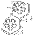
FIG. 1 is a diagram of a pattern repeated in a first embodiment of the present invention; -
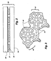
FIG. 2 is a sectional view of a microwave packaging material according to the present invention; -
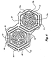
FIG. 3 is a diagram of a pattern repeated in a second embodiment of the present invention; -
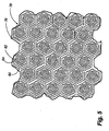
FIG. 4 is a diagram of a pattern repeated in a third embodiment of the present invention; -
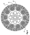
FIG. 5 is a diagram of a sheet of microwave packaging material according to a third embodiment of the present invention; -
FIG. 6 is diagram of a quasi-shielding wall according to the present invention; -
FIG. 7 is the graph from Example 1; -
FIG. 8 is the graph from Example 2; -
FIG. 9 is the graph from Example 3; and -
FIG. 10 is the graph from Example 4. - For a better understanding of the invention, the following detailed description refers to the accompanying drawings, wherein preferred exemplary embodiments of the present invention are illustrated and described.
- The present invention relates to an abuse-tolerant, high-heating-efficiency metallic material used in microwave packaging materials. This abuse-tolerant material redistributes incident microwave energy so as to increase reflection of microwave energy while maintaining high microwave energy absorption. A repeated pattern of metallic foil segments can shield microwave energy almost as effectively as a continuous bulk foil material while stiff absorbing and focusing microwave energy on an adjacent food surface. The microwave metallic segments can be made of foil or high optical density evaporated materials. High optical density materials include evaporated metallic films which have an optical density greater than one (optical density being derived from the ratio of light reflected to light transmitted). High optical density materials generally have a shiny appearance, whereas thinner metallic materials, such as susceptor films have a flat, opaque appearance. Preferably, the metallic segments are foil segments.
- The segmented foil (or high optical density material) structure prevents large induced currents from building at the edges of the material or around tears or cuts in the material, thus diminishing the occurrences of arcing, charring or fires caused by large induced currents and voltages. The present invention includes a repeated pattern of small metallic segments, wherein each segment acts as a heating element when under the influence of microwave energy. In the absence of a food (dielectric) load, this energy generates only a small induced current in each element and hence a very low field strength close to its surface.
- Preferably, the power reflection of the abuse-tolerant material is increased by combining the material in accordance with the present invention with a layer of conventional susceptor film. In this configuration, a high surface heating environment is created through the additional excitement of the susceptor film due to the composite action of food contacting the small metallic segments. When the food contacts the metallic segments of the abuse-tolerant material according to the present invention, the quasi-resonant characteristic of perimeters defined by the metallic segments can stimulate stronger and more uniform cooking. Unlike a full sheet plain susceptor, the present invention can stimulate uniform heating between the edge and center portion of a sheet of material to achieve a more uniform heating effect. The average width and perimeter of the pattern of metallic segments will determine the effective heating strength of the pattern and the degree of abuse tolerance of the pattern. However, the power transmittance directly toward the food load through an abuse-tolerant metallic material according to the present invention is dramatically decreased, which leads to a quasi-shielding functionality. In the absence of food contacting the material, according to the present invention, the array effect of the small metallic segments still maintains a generally transparent characteristic with respect to microwave power radiation. Thus, the chances of arcing or burning when the material is unloaded or improperly loaded are diminished.
- Preferably, each metallic segment has an area less than 5 mm2 and the gap between each small metallic strip is larger than 1 mm. Metallic segments of such size and arrangement reduce the threat of arcing which exists under no load conditions in average microwave ovens. When, for example, food, a glass tray, or a layer of plain susceptor film contacts the metallic segments, the capacitance between adjacent metallic segments will be raised as each of these substances has a dielectric constant much larger than a typical substrate on which the small metal segments are located. Of these materials, food has the highest dielectric constant (often by an order of magnitude). This creates a continuity effect of connected metallic segments which then work as a low Q-factor resonate loop, power transmission line, or power reflection sheet with the same function of many designs that would otherwise be unable to withstand abuse conditions. On the other hand, the pattern is detuned from the resonant characteristic in the absence of food. This selectively tuned effect substantially equalizes the heating capability over a fairly large packaging material surface including areas with and without food.
- Turning to the drawing figures,
FIGS. 1-3 show three respective embodiments of patterns of metallic foil segments according to the present invention. In a first embodiment in accordance with the present invention shown inFIG. 1 , a first set of spaced bentmetallic segments 22 define a first perimeter, orloop 24. According to the present invention, the length of the perimeter is preferably approximately equal to a multiple of one-half an operating wavelength of a microwave oven (i.e., 0.5λ, 1λ, 1.5λ and so on). The perimeter of a set of segments can be other ratios of the operating wavelength. In the first embodiment, theperimeter 24 is approximately equal to one full operating wavelength of a microwave oven. Preferably themetallic segments 22 are arranged to define a five-lobed flower shape seen in each of the respective embodiments shown inFIGS. 1-3 . The five-lobed flower arrangement promotes the even distribution of microwave energy to adjacent food. Metallic segments defining other shapes such as circles, ovals, polygonal shapes and so on are within the scope of the present invention. - Preferably, each first set of
metallic segments 22 is accompanied by an enclosing second set of straightmetallic segments 30. The second set ofmetallic segments 30 also preferably define asecond perimeter 32 having a length approximately equal to the operating wavelength of a microwave oven. The sets ofmetallic segments FIG. 1 , but described later in connection withFIG. 5 ), which is continuously repeated to create a desired quasi-shielding effect. Preferably, the outer set of segments (the second set ofsegments 30 in the first embodiment) define the hexagonalsecond perimeter 32 with a shape which allows each set ofmetallic segments 30 to be nested with adjacent second sets ofmetallic segments 30. Nested arrays of resonant hexagonal loops are described in commonly ownedU.S. Patent Application Serial No. 60/037,907 and are discussed in more detail in reference toFIG. 5 . The hexagon is an excellent basic polygon to select due to its ability to nest perfectly along with its high degree of cylindrical symmetry. The first and second sets of metallic segments are repeated on a substrate to create the patterned material of the present invention. - The sets of
metallic segments U.S. Patent Nos. 4,398,994 ,4,552,614 ,5,310,976 ,5,266,386 and5,340,436 . Alternately, the metallic segments may be formed on a susceptor film (i.e., a metallized polymeric film) using the same techniques. Segments of high optical density evaporated materials can be produced by similar etching techniques or by evaporating the material onto a masked surface to achieve the desired pattern. Both techniques are well known in the art. -
FIG. 2 shows a schematic sectional view ofmetallic segments 30 formed on asubstrate 34 and including a susceptor film 36 having a metallizedlayer 37 and apolymer layer 39 to form amicrowave packaging material 38 according to the present invention. - In a second embodiment shown in
FIG. 3 , a first set of bentmetallic segments 40 define afirst perimeter 42 having a length equal to one-half an operating wavelength of a microwave. Like the first embodiment, thefirst perimeter 42 preferably defines a multi-lobed shape in order to evenly distribute microwave energy. The smaller perimeter pattern shown inFIG. 3 has a higher reflection effect under light or no loading than the larger perimeter pattern shown inFIG. 1 , at the expense of a proportionate amount of microwave energy absorption and heating power. A second set ofmetallic segments 44 encloses the first set ofmetallic segments 40 and defines asecond perimeter 46 approximately equal to one-half the operating frequency of a microwave. Preferably, the second set ofmetallic segments 44 are arranged in a nested configuration and define a hexagonal second perimeter. - A third embodiment of a pattern of metallic segments, in accordance with the present invention, is shown in
FIG. 4 . The third embodiment includes a third set ofmetallic segments 60 in addition to first and second sets ofmetallic segments second perimeters segments 60 encloses the second set ofmetallic segments 64 and define athird perimeter 68. Preferably the third set ofsegments 60 define a hexagonalthird perimeter 68. In the third embodiment, additionalmetallic segments 70a, b, c are preferably included within each lobe 72 (70a) between each lobe 72 (70b) and at a center 74 (70c) of the five-lobed flower shape defined by the first set ofmetallic segments 62. The additionalmetallic segments 70a and b which are arranged between and within thelobes 72 preferably are triangular shaped with a vertex pointing in the direction of thecenter 74 of the flower shape. Theadditional segments 70a, b, c further enhance the even distribution of microwave energy, in particular from the edges of the perimeter to the center of the perimeter. - An example of a sheet of microwave packaging material according to the present invention is shown in
FIG. 5 . A pattern according to the third embodiment shown inFIG. 4 is repeated on asubstrate 76 which may be microwave transparent (e.g., paperboard), or include a susceptor film. Preferably, the third set ofmetallic segments 60 is repeated with the first and second 62, 64 sets of metallic segments in a nestedarray 78 best seen inFIG. 5 . A nestedarray 78 is an arrangement wherein each of the metallic segments in an outer set of metallic segments is shared by adjacent sets of metallic segments (i.e., one strip of metallic segments divides one first or second set of segments from another first or second set). The nestedarray 78 contributes to the continuity of the overall pattern and therefore to the quasi-shielding effect of the present invention. Furthermore, outer sets of metallic segments are preferably arranged to define a hexagonal shape to better facilitate a nestedarray 78 of sets of metallic segments. - Preferably, in the pattern according to the third embodiment shown in
FIGS. 4 and5 , the second set ofmetallic segments 64 defines the second perimeter approximately equal to a multiple of one-half the effective wavelength of microwaves and thethird perimeter 68 defined by the third set ofmetallic segments 60 with a similar, but deliberately altered perimeter length. - Note, the effective wavelength, λeff, of a microwaves in a dielectric material (e.g., food products) is calculated by the formula

- Further advantages and features of the present invention are discussed in the context of the following examples. graphs show that a susceptor including a segmented foil pattern shown in
FIG. 3 performed a higher power reflection than the plain susceptor at E-field strength of 6 kV/m under an open load. The power reflection for plain susceptor reaches 54% at low E-field strength radiation and 16% at high E-field strength radiation. While power reflection of a susceptor laminated to arrays of metallic segments according to the present invention susceptor gives 77% at low E-field radiation and 34% at high E-field radiation. The graphs (fig. 7 ) demonstrate that a material including a repeated pattern of metallic segments according to the present invention has much improved shielding characteristics compared to plain susceptor material. -
Applied Electric Field (kV/m) Plain Susceptor Transmission Reflection Absorption Present Invention Transmission Reflection Absorption 0.0 6% 54% 40% 1% 77% 21% 3.9 14% 46% 40% 4% 68% 28% 5.6 50% 16% 34% 40% 37% 26% 6.8 37% 13% 29% 45% 33% 21% 7.9 66% 14% 21% 69% 21% 11% 8.8 65% 13% 22 % 67l5 20% 14% 9.6 66% 12% 22% 67% 19% 14% - Example 2 shows RAT performance of the third embodiment of the present invention (
FIG. 4 ) laminated on a susceptor. The measurements were taken with a layer of pastry in contact with the packaging material according to the present invention. The quasi-resonance and power reflection effect occurs when the food is in contact with the metallic segments so as to complete the segmented pattern. The test showed (fig. 8 ) that the power reflection of the present invention 73% to 79% (plain bulk metallic foil has a power reflection of 100%). This test demonstrates that the present invention can be used as a quasi-shielding material in microwave food packaging. The benefit of the present invention is that, unlike bulk metallic foil, it is abuse-tolerant and safe for microwave oven cooking yet still has much of the shielding effect of bulk metallic foil when loaded with food (even under the very high stress conditions of this test). -
Applied Electric Field (kV/m) Present Invention Transmission Reflection Absorption 0.0 1% 79% 20% 3.9 4% 70% 26% 5.6 4% 73% 23% 6.8 4% 86% 10% 7.9 4% 82% 15% 8.8 12% 87% 1% 9.6 21% 78% 1% - Example 3 shows the stability of the power reflection performance of both a plain susceptor and the microwave packaging material according to the third embodiment (
FIGS. 4 and5 ) the present invention laminated to a susceptor under increasing E-field strengths in open load operation. RAT characteristic data of each material was measured after two minutes of continuous radiation in each level of E-field strength. The test (fig. 9 ) showed that the metallic strip susceptor material is also more durable than the plain susceptor. While not wishing to be bound by one particular theory, the inventors presently believe that the increased durability of the present invention results from the metallic segments imparting mechanical stability to the polymer layer commonly included in susceptor films. -
E-Field Strength (Kv/m) Reflection Transmission Absorption Film Appearance Plain Susceptor on Paperboard 0 63% 4% 33% no crack 5 19% 52% 28% visible crack 10 9% 80% 11% crack Present Invention 0 77% 9% 14% no crack 5 36% 50% 14% no crack 10 11% 75% 14% slight cracked lines - Temperature profiles of frozen chicken under heating with metallic patterned susceptor sleeves according to the present invention are shown in Example 4. Three fiber-optic temperature probes were placed at the different portion of frozen chicken to monitor the cooking temperature. The test results (
fig. 10 ) indicated that the patterned metallic segments included with a susceptor sleeve delivered a high surface temperature which causes good surface crisping of the chicken. Note that the center of the chicken heated after the surface and tip of the chicken were heated. This is close to the heating characteristics which would be observed in a conventional oven. The chicken cooked using microwave packaging according to the present invention achieved comparable results to a chicken cooked in a conventional oven. The chicken had a browned, crisped surface and the meat retained its juices. - A metallic patterned susceptor lid according to the present invention as seen in
FIG. 5 was used for microwave baking of a 28 oz. frozen fruit pie. It takes approximately 15 minutes in a 900 watt output power oven to bake such a pie. As seen inFIG. 5 , the lid of this cooking package used the metallic patterned susceptor sheet with periodical array of the basic structure shown inFIG. 4 . Both the lid and tray are abuse-tolerant and safe for operation in a microwave oven. Testing showed this lid generated an even baking over the top surface. The lid can be exposed to an E-field strength as high as 15 kV/m unloaded by food without any risk of charring, arcing, or fire in the packaging or paper substrate tray. - In another experiment, the baking results for raw pizza dough using two kinds of reflective walls were compared. One wall is made with an aluminum foil sheet and the other was made from a packaging material according to the present invention. The quasi-shielding wall according to the present invention is shown in
FIG. 6 . A 7 µm thick aluminum foil was used in both wall structures (i.e., the metallic segments of the packaging material according to the present invention are 7 µm thick). Fairly similar baking performance was achieved in both pizzas. Thus the packaging material according to the present invention achieved the same good results as the less safe bulk foil. - The present invention can be used in several formats such as baking lids, trays and disks, with or without a laminated layer of susceptor film. In general, a susceptor laminated with the present invention is able to generate higher reflection of radiation power than a plain susceptor at the same level of input microwave power. The present invention can be treated as an effective quasi-shielding material for various microwave food packaging applications.
- The present invention has been described with reference to a preferred embodiment. However, it will be readily apparent to those skilled in the art that it is possible to embody the invention in specific forms other than as described above without departing from the scope of the invention. The preferred embodiment is illustrative and should not be considered restrictive in any way. The scope of the invention is given by the appended claims, rather than the preceding description, and all variations and equivalents which fall within the range of the claims are intended to be embraced therein.
Claims (25)
- An abuse-tolerant microwave packaging material for a microwavable food product, the abuse-tolerant microwave packaging material comprising:a continuously repeated first set of segments (22) formed of a metallic foil or of a high optical density evaporated material, the first set of segments (22) located on a substrate, each first set of segments (22) defining a first perimeter (24) having a length approximately equal to a multiple of one-half of the effective wavelength of a microwave oven, and each segment (22) in each first set being spaced from adjacent segments, wherein the effective wavelength of the microwave oven is defined as the wavelength of a microwave in air divided by the square root of the dielectric constant of the food product.
- The abuse-tolerant microwave packaging material of Claim 1, wherein the length of the first perimeter (24) is approximately equal to one-half of the effective wavelength.
- The abuse-tolerant microwave packaging material of Claim 1, wherein the length of the first perimeter (24) is approximately equal to the effective wavelength.
- The abuse-tolerant microwave packaging material of Claim 1 comprising:a continuously repeated second set of segments (30) formed of a metallic foil or of a high optical density evaporated material, each second set defining a second perimeter (32) enclosing one of the continuously repeated first sets of segments (22), the second perimeter (32) having a length being approximately equal to a predetermined ratio of the effective wavelength, wherein each metallic segment (30) of each second set is spaced from adjacent segments.
- The abuse-tolerant microwave packaging material of Claim 4, wherein the length of the second perimeter (32) is approximately equal to a multiple of one-half of the effective wavelength.
- The abuse-tolerant microwave packaging material of Claim 4, wherein the length of the second perimeter (32) is approximately equal to one-half of the effective wavelength for the food product in a frozen state.
- The abuse-tolerant microwave packaging material of Claim 4, wherein the length of the second perimeter (32) is approximately equal to the effective wavelength for the food product in a thawed state.
- The abuse-tolerant microwave packaging material of Claim 4, wherein the second set of segments (30) defines a hexagonal shape.
- The abuse-tolerant microwave packaging material of Claim 4, wherein each of the second set of segments (30) is nested with adjacent second sets of segments.
- The abuse-tolerant microwave packaging material of Claim 4 comprising:a repeated third set of segments (60) formed of a metallic foil or of a high optical density evaporated material, each third set defining a third perimeter (68) enclosing one of the repeated second sets of microwave-interactive elements (64), the third perimeter (68) having a length being approximately equal to a predetermined ratio of the effective wavelength, wherein the segments (60) in each of the third sets are spaced from adjacent segments.
- The abuse-tolerant microwave packaging material of Claim 10, wherein the length of the third perimeter (68) is approximately equal to a multiple of one-half of the effective wavelength.
- The abuse-tolerant microwave packaging material of Claim 10, wherein the length of the third perimeter (68) is approximately equal to one-half of the effective wavelength for the food product in a frozen state.
- The abuse-tolerant microwave packaging material of Claim 10, wherein the length of the third perimeter (68) is approximately equal to the effective wavelength for the food product in a thawed state.
- The abuse-tolerant microwave packaging material of Claim 10, wherein the third set of segments (60) defines a hexagonal shape.
- The abuse-tolerant microwave packaging material of Claim 10, wherein each of the third sets of segments (60) is nested with adjacent third sets of segments.
- The abuse-tolerant microwave packaging material of Claim 1, wherein each of the repeated first sets of segments (22) defines a multi-lobe shape.
- The abuse-tolerant microwave packaging material of Claim 16, wherein the multi-lobe shape is a five-lobe flower shape.
- The abuse-tolerant microwave packaging material of Claim 1, wherein each segment has an area of less than 5 mm2.
- The abuse-tolerant microwave packaging material of Claim 1, wherein the substrate includes a susceptor film.
- The abuse-tolerant microwave packaging material of Claim 1, wherein the substrate is microwave transparent.
- The abuse-tolerant microwave packaging material of Claim 20, wherein the substrate is a paper based material.
- The abuse-tolerant microwave packaging material of any of Claims 1 to 21, wherein the segments formed of a metallic foil or of a high optical density evaporated material are metallic foil segments.
- The abuse-tolerant microwave packaging material of Claim 22, wherein the metallic foil segments are formed of aluminium.
- The abuse-tolerant microwave packaging material of any of Claims 1 to 21, wherein the segments formed of a metallic foil or of a high optical density evaporated material are segments of a high optical density evaporated material.
- The abuse-tolerant microwave packaging material of Claim 24, wherein the segments of a high optical density evaporated material are formed of aluminium.
Applications Claiming Priority (3)
| Application Number | Priority Date | Filing Date | Title |
|---|---|---|---|
| US09/399,182 US6204492B1 (en) | 1999-09-20 | 1999-09-20 | Abuse-tolerant metallic packaging materials for microwave cooking |
| US399182 | 1999-09-20 | ||
| PCT/US2000/040930 WO2001022778A1 (en) | 1999-09-20 | 2000-09-18 | Abuse-tolerant metallic packaging materials for microwave cooking |
Publications (3)
| Publication Number | Publication Date |
|---|---|
| EP1131983A1 EP1131983A1 (en) | 2001-09-12 |
| EP1131983A4 EP1131983A4 (en) | 2003-03-26 |
| EP1131983B1 true EP1131983B1 (en) | 2010-01-13 |
Family
ID=23578488
Family Applications (1)
| Application Number | Title | Priority Date | Filing Date |
|---|---|---|---|
| EP00974122A Expired - Lifetime EP1131983B1 (en) | 1999-09-20 | 2000-09-18 | Abuse-tolerant metallic packaging materials for microwave cooking |
Country Status (8)
| Country | Link |
|---|---|
| US (1) | US6204492B1 (en) |
| EP (1) | EP1131983B1 (en) |
| JP (2) | JP3975462B2 (en) |
| AT (1) | ATE455450T1 (en) |
| AU (1) | AU1253601A (en) |
| CA (1) | CA2334690C (en) |
| DE (1) | DE60043691D1 (en) |
| WO (1) | WO2001022778A1 (en) |
Families Citing this family (175)
| Publication number | Priority date | Publication date | Assignee | Title |
|---|---|---|---|---|
| US6433322B2 (en) * | 1999-09-20 | 2002-08-13 | Graphic Packaging Corporation | Abuse-tolerant metallic packaging materials for microwave cooking |
| US6559430B2 (en) * | 2001-01-04 | 2003-05-06 | General Mills, Inc. | Foil edge control for microwave heating |
| US6717121B2 (en) | 2001-09-28 | 2004-04-06 | Graphic Packaging International, Inc. | Patterned microwave susceptor element and microwave container incorporating same |
| AU2005201617B2 (en) * | 2001-09-28 | 2005-05-12 | Graphic Packaging International, Inc. | Patterned microwave susceptor element and microwave container incorporating same |
| US7319213B2 (en) * | 2001-11-07 | 2008-01-15 | Graphic Packaging International, Inc. | Microwave packaging with indentation patterns |
| US6919547B2 (en) * | 2001-11-07 | 2005-07-19 | Graphic Packaging International, Inc. | Microwave packaging with indentation patterns |
| US6677563B2 (en) | 2001-12-14 | 2004-01-13 | Graphic Packaging Corporation | Abuse-tolerant metallic pattern arrays for microwave packaging materials |
| WO2003066435A2 (en) * | 2002-02-08 | 2003-08-14 | Graphic Packaging International, Inc. | Insulating microwave interactive packaging |
| US7323669B2 (en) * | 2002-02-08 | 2008-01-29 | Graphic Packaging International, Inc. | Microwave interactive flexible packaging |
| ES2396314T3 (en) | 2002-03-15 | 2013-02-20 | Graphic Packaging International, Inc. | Procedure and tool for forming a container that has an injection molding characteristic |
| FR2862491B1 (en) * | 2003-11-25 | 2006-07-28 | Marie Surgeles | CULINARY PREPARATION INTENDED FOR MICROWAVE OVEN HEATING. |
| JP4327205B2 (en) * | 2004-02-09 | 2009-09-09 | グラフィック パッケージング インターナショナル インコーポレイテッド | Microwave cooking package |
| CA2577150C (en) | 2004-08-25 | 2010-02-23 | Graphic Packaging International, Inc. | Absorbent microwave interactive packaging |
| US7982168B2 (en) * | 2004-08-25 | 2011-07-19 | Graphic Packaging International, Inc. | Absorbent microwave interactive packaging |
| CN100561286C (en) * | 2004-09-17 | 2009-11-18 | 鸿富锦精密工业(深圳)有限公司 | digital camera wide angle lens |
| US20060096978A1 (en) * | 2004-11-10 | 2006-05-11 | Graphic Packaging International, Inc | Insulated packages for microwaveable foods |
| US7425296B2 (en) * | 2004-12-03 | 2008-09-16 | Pressco Technology Inc. | Method and system for wavelength specific thermal irradiation and treatment |
| US10857722B2 (en) * | 2004-12-03 | 2020-12-08 | Pressco Ip Llc | Method and system for laser-based, wavelength specific infrared irradiation treatment |
| US10687391B2 (en) | 2004-12-03 | 2020-06-16 | Pressco Ip Llc | Method and system for digital narrowband, wavelength specific cooking, curing, food preparation, and processing |
| US7514659B2 (en) * | 2005-01-14 | 2009-04-07 | Graphic Packaging International, Inc. | Package for browning and crisping dough-based foods in a microwave oven |
| ATE497918T1 (en) * | 2005-04-11 | 2011-02-15 | Graphic Packaging Int Inc | MICROWAVE HEATABLE, EASY TO OPEN FOOD PACKAGING |
| JP4950179B2 (en) * | 2005-04-14 | 2012-06-13 | グラフィック パッケージング インターナショナル インコーポレイテッド | Thermally active microwave interaction material |
| US20110204046A1 (en) * | 2005-05-25 | 2011-08-25 | Middleton Scott W | Microwave Heating Construct for Frozen Liquids and Other Items |
| DE602006020282D1 (en) * | 2005-05-25 | 2011-04-07 | Graphic Packaging Int Inc | MICROWAVE PACKING FOR MEASURES COMPRISING MULTIPLE COMPONENTS |
| EP1899243B1 (en) | 2005-06-17 | 2019-09-18 | Graphic Packaging International, LLC | Susceptors capable of balancing stress and effectiveness |
| US20070184977A1 (en) * | 2005-07-29 | 2007-08-09 | Spiller Robert W | Microwavable construct with thermally responsive indicator |
| US7361872B2 (en) | 2005-08-16 | 2008-04-22 | Graphic Packaging International, Inc. | Variable serving size insulated packaging |
| ES2387576T3 (en) | 2005-09-12 | 2012-09-26 | Graphic Packaging International, Inc. | Highly manufactured product for microwave heating |
| US7345262B2 (en) * | 2005-11-07 | 2008-03-18 | Graphic Packaging International, Inc. | Microwave interactive display package |
| US7982167B2 (en) | 2005-12-08 | 2011-07-19 | Graphic Packaging International, Inc. | Microwave food heating package with removable portion |
| US8598500B2 (en) * | 2005-12-19 | 2013-12-03 | E I Du Pont De Nemours And Company | Arc-resistant microwave susceptor assembly |
| US8367988B2 (en) * | 2005-12-19 | 2013-02-05 | E I Du Pont De Nemours And Company | Field director assembly having overheating protection |
| WO2007103428A2 (en) * | 2006-03-09 | 2007-09-13 | Graphic Packaging International, Inc. | Susceptor with apertured support |
| US8124201B2 (en) * | 2006-03-10 | 2012-02-28 | Graphic Packaging International, Inc. | Injection-molded composite construct |
| EP1993928B1 (en) | 2006-03-10 | 2011-05-11 | Graphic Packaging International, Inc. | Container with microwave interactive web |
| US8853601B2 (en) | 2006-03-31 | 2014-10-07 | Graphic Packaging International, Inc. | Microwavable construct for heating, browning, and crisping rounded food items |
| WO2007126829A2 (en) * | 2006-03-31 | 2007-11-08 | Graphic Packaging International, Inc. | Construct for supporting food items |
| EP1840047B1 (en) * | 2006-03-31 | 2009-08-26 | Graphic Packaging International, Inc. | Microwavable construct for heating, browning and crisping rounded food item |
| GB0606676D0 (en) * | 2006-04-03 | 2006-05-10 | Heinz Co H J | Packaging For Food Products |
| US9205968B2 (en) | 2006-04-27 | 2015-12-08 | Graphic Packaging International, Inc. | Multidirectional fuse susceptor |
| US8063344B2 (en) * | 2006-04-27 | 2011-11-22 | Graphic Packaging International, Inc. | Microwave energy interactive food package |
| EP2013111B1 (en) * | 2006-04-27 | 2010-06-23 | Graphic Packaging International, Inc. | Multidirectional fuse susceptor |
| WO2007133659A2 (en) | 2006-05-12 | 2007-11-22 | Graphic Packaging International, Inc. | Microwave energy interactive heating sheet |
| US8803050B2 (en) * | 2006-05-15 | 2014-08-12 | Graphic Packaging International, Inc. | Microwavable construct with contoured heating surface |
| US8680448B2 (en) * | 2006-05-15 | 2014-03-25 | Graphic Packaging International, Inc. | Microwavable construct with contoured heating surface |
| WO2007133767A2 (en) | 2006-05-15 | 2007-11-22 | Graphic Packaging International, Inc. | Microwavable construct with contoured heating surface |
| US7824719B2 (en) * | 2006-05-19 | 2010-11-02 | Graphic Packaging International, Inc. | Cooking package |
| US8826959B2 (en) | 2006-06-29 | 2014-09-09 | Graphic Packaging International, Inc. | Heat sealing systems and methods, and related articles and materials |
| US8753012B2 (en) * | 2006-06-29 | 2014-06-17 | Graphic Flexible Packaging, Llc | High strength packages and packaging materials |
| EP2059457B1 (en) | 2006-06-30 | 2015-02-25 | Graphic Packaging International, Inc. | Microwave heating package with thermoset coating |
| US8198571B2 (en) | 2006-07-05 | 2012-06-12 | Graphic Packaging International, Inc. | Multi-compartment microwave heating package |
| EP2772452B1 (en) | 2006-07-27 | 2016-01-06 | Graphic Packaging International, Inc. | Microwave heating construct |
| EP1886936A1 (en) * | 2006-08-11 | 2008-02-13 | Graphic Packaging International, Inc. | Construct for heating a rounded food item in a microwave oven and blank therefore |
| EP1886926A1 (en) * | 2006-08-11 | 2008-02-13 | Graphic Packaging International, Inc. | Construct for heating multiple food items in a microwave oven |
| ES2625132T3 (en) * | 2006-10-16 | 2017-07-18 | Graphic Packaging International, Inc. | Product manufactured high microwave heating |
| WO2008049048A2 (en) * | 2006-10-18 | 2008-04-24 | Graphic Packaging International, Inc. | Tool for forming a three dimensional article or container |
| ATE512064T1 (en) * | 2006-10-26 | 2011-06-15 | Graphic Packaging Int Inc | RAISED TRAY FOR MICROWAVE HEATING |
| CN103225830B (en) * | 2007-01-22 | 2016-01-20 | 印刷包装国际公司 | Heating using microwave component and the blank for the formation of this component |
| JP5722545B2 (en) * | 2007-02-08 | 2015-05-20 | グラフィック パッケージング インターナショナル インコーポレイテッド | Microwave energy interactive insulation sheet and system |
| US9073689B2 (en) * | 2007-02-15 | 2015-07-07 | Graphic Packaging International, Inc. | Microwave energy interactive insulating structure |
| US8629380B2 (en) * | 2007-03-23 | 2014-01-14 | Graphic Packaging International, Inc. | Susceptor with corrugated base |
| US20080230537A1 (en) | 2007-03-23 | 2008-09-25 | Lafferty Terrence P | Susceptor with corrugated base |
| EP2139788A4 (en) * | 2007-05-01 | 2011-05-04 | Graphic Packaging Int Inc | Package for heating a food product |
| WO2008137525A2 (en) * | 2007-05-01 | 2008-11-13 | Graphic Packaging International, Inc. | Package for heating a food product |
| CA2937567C (en) | 2007-05-15 | 2019-06-04 | Graphic Packaging International, Inc. | Microwavable construct with contoured heating surface |
| WO2008157750A2 (en) * | 2007-06-21 | 2008-12-24 | Graphic Packaging International, Inc. | Package for containing and dispensing a food item |
| CA2694535C (en) | 2007-08-13 | 2013-05-07 | Graphic Packaging International, Inc. | Package with enlarged base |
| US20090090708A1 (en) * | 2007-10-03 | 2009-04-09 | Emili Requena | Microwave Heating Sleeve |
| JP5220867B2 (en) | 2007-12-28 | 2013-06-26 | グラフィック パッケージング インターナショナル インコーポレイテッド | Injection molded composite structure and tool for forming the structure |
| EP2231376B1 (en) * | 2007-12-31 | 2015-08-05 | Graphic Packaging International, Inc. | Tool and method for forming construct |
| US20090186133A1 (en) * | 2008-01-22 | 2009-07-23 | Chris Bjork | Microwaveable cup arrangement and methods |
| ES2523716T3 (en) * | 2008-02-18 | 2014-12-01 | Graphic Packaging International, Inc. | Apparatus for preparing a food item in a microwave oven |
| CA2715590C (en) * | 2008-02-18 | 2014-10-21 | Graphic Packaging International, Inc. | Apparatus for cooking raw food items in a microwave oven |
| US20090223951A1 (en) * | 2008-03-04 | 2009-09-10 | Lai Laurence M C | Constructs and Methods for Heating a Liquid in a Microwave Oven |
| JP5421297B2 (en) | 2008-03-14 | 2014-02-19 | グラフィック パッケージング インターナショナル インコーポレイテッド | Susceptor with waveform base |
| CA2719414C (en) * | 2008-03-27 | 2013-09-03 | Graphic Packaging International, Inc. | Self-venting microwave heating package |
| US7975871B2 (en) | 2008-04-04 | 2011-07-12 | Graphic Packaging International, Inc. | Container with injection-molded feature and tool for forming container |
| WO2009137642A2 (en) * | 2008-05-09 | 2009-11-12 | Graphic Packaging International, Inc. | Microwave energy interactive tray and wrap |
| WO2009152120A2 (en) * | 2008-06-09 | 2009-12-17 | Graphic Packaging International, Inc. | Microwave energy interactive structure with microapertures |
| JP5788792B2 (en) | 2008-07-11 | 2015-10-07 | グラフィック パッケージング インターナショナル インコーポレイテッド | Microwave heating vessel |
| CA2729600C (en) * | 2008-07-14 | 2014-06-10 | Graphic Packaging International, Inc. | Cooking package |
| EP2493263B1 (en) * | 2008-07-31 | 2014-06-25 | Graphic Packaging International, Inc. | Microwave heating construct |
| EP2610196B1 (en) | 2008-08-14 | 2014-07-30 | Graphic Packaging International, Inc. | Microwave heating construct and method of using same |
| JP5496207B2 (en) * | 2008-09-17 | 2014-05-21 | グラフィック パッケージング インターナショナル インコーポレイテッド | Structure for baking and crunching food in a microwave oven |
| US20110024413A1 (en) * | 2008-09-17 | 2011-02-03 | Cole Lorin R | Construct for Browning and Crisping a Food Item in a Microwave Oven |
| JP5302410B2 (en) | 2008-11-12 | 2013-10-02 | グラフィック パッケージング インターナショナル インコーポレイテッド | Susceptor structure |
| US8815317B2 (en) | 2009-01-12 | 2014-08-26 | Graphic Packaging International, Inc. | Elevated microwave heating construct |
| US20110011854A1 (en) * | 2009-02-23 | 2011-01-20 | Middleton Scott W | Low crystallinity susceptor films |
| US20100213191A1 (en) * | 2009-02-23 | 2010-08-26 | Middleton Scott W | Low Crystallinity Susceptor Films |
| US9284108B2 (en) | 2009-02-23 | 2016-03-15 | Graphic Packaging International, Inc. | Plasma treated susceptor films |
| US20100213192A1 (en) * | 2009-02-23 | 2010-08-26 | Middleton Scott W | Plasma Treated Susceptor Films |
| ES2696990T3 (en) | 2009-04-20 | 2019-01-21 | Graphic Packaging Int Llc | Multilayer susceptor structure |
| CA2757009C (en) | 2009-04-28 | 2015-08-25 | Graphic Packaging International, Inc. | Vented susceptor structure |
| WO2010127214A2 (en) * | 2009-05-01 | 2010-11-04 | Graphic Packaging International, Inc. | Construct with locating feature |
| EP2442924A4 (en) | 2009-06-17 | 2017-03-01 | Graphic Packaging International, Inc. | Tool for forming a three dimensional container or construct |
| EP2937378A1 (en) | 2009-07-30 | 2015-10-28 | Graphic Packaging International, Inc. | Low crystallinity susceptor films |
| US8777010B2 (en) * | 2009-08-26 | 2014-07-15 | Graphic Packaging International, Inc. | Container blank and container with denesting feature |
| EP2477900B1 (en) | 2009-09-14 | 2015-08-12 | Graphic Packaging International, Inc. | Blank and forming tool for forming a container |
| US8727204B2 (en) * | 2009-11-16 | 2014-05-20 | Graphic Packaging International, Inc. | Expandable carton |
| JP5535332B2 (en) * | 2009-11-30 | 2014-07-02 | グラフィック パッケージング インターナショナル インコーポレイテッド | Microwave heating structure having a ventilation mechanism |
| US8604401B2 (en) * | 2009-12-09 | 2013-12-10 | Graphic Packaging International, Inc. | Deep dish microwave heating construct |
| EP2519404A2 (en) * | 2009-12-30 | 2012-11-07 | Graphic Packaging International, Inc. | Apparatus and method for positioning and operating upon a construct |
| WO2011091339A2 (en) * | 2010-01-25 | 2011-07-28 | Graphic Packaging International, Inc. | Package for multiple food items |
| CA2786050C (en) * | 2010-03-11 | 2015-06-16 | Graphic Packaging International, Inc. | Microwave heating package for frozen food items |
| US9000339B2 (en) * | 2010-03-29 | 2015-04-07 | Graphic Packaging International, Inc. | Microwave heating apparatus with food supporting cradle |
| KR102173068B1 (en) | 2010-06-11 | 2020-11-02 | 프레스코 아이피 엘엘씨 | Cookware and cook-packs for narrowband irradiation cooking and systems and methods thereof |
| US9332877B2 (en) | 2010-06-11 | 2016-05-10 | Pressco Ip Llc | Cookware and cook-packs for narrowband irradiation cooking and systems and methods thereof |
| CA2813421A1 (en) | 2010-10-21 | 2012-04-26 | Graphic Packaging International, Inc. | Substantially round tray |
| JP5745260B2 (en) * | 2010-12-07 | 2015-07-08 | 東罐興業株式会社 | Container for heating microwave oven and cooking method using the same |
| US8993944B2 (en) | 2011-02-14 | 2015-03-31 | Board Of Trustees Of Michigan State University | Microwaveable packaging for food products including a frozen component |
| CN103597910B (en) | 2011-04-25 | 2016-10-12 | 印刷包装国际公司 | Microwave energy interaction bag |
| WO2012170600A2 (en) * | 2011-06-08 | 2012-12-13 | Graphic Packaging International, Inc. | Tray with curved bottom surface |
| CN103717387B (en) | 2011-08-03 | 2017-11-07 | 印刷包装国际公司 | Systems and methods for forming laminates with patterned microwave energy interacting materials |
| ES2616977T3 (en) | 2012-03-12 | 2017-06-15 | Coneinn Marketing, B.V. | Packaging with field modifiers for improved microwave heating of cone-shaped products |
| ES2647635T3 (en) | 2012-10-17 | 2017-12-22 | Graphic Packaging International, Inc. | Container with incision lines |
| KR101389768B1 (en) * | 2013-02-26 | 2014-04-28 | 주식회사 홈스타 | Cooking wear with pattern |
| EP2967246B1 (en) | 2013-03-15 | 2018-01-31 | Graphic Packaging International, Inc. | Container with heating features |
| WO2014190266A1 (en) | 2013-05-24 | 2014-11-27 | Graphic Packaging International, Inc. | Package for combined steam and microwave heating of food |
| MX381051B (en) | 2013-07-25 | 2025-03-12 | Graphic Packaging Int Llc | Carton for a food product |
| US9957080B2 (en) | 2013-09-25 | 2018-05-01 | Graphic Packaging International, Llc | Reinforced package |
| EP3049338B1 (en) | 2013-09-25 | 2018-12-26 | Graphic Packaging International, LLC | Reinforced package |
| US9771176B2 (en) | 2013-09-25 | 2017-09-26 | Graphic Packaging International, Inc. | Reinforced package |
| ES2702380T3 (en) | 2013-09-26 | 2019-02-28 | Graphic Packaging Int Llc | Stratified, and systems and procedures for stratification |
| CA2928099C (en) | 2013-12-16 | 2018-03-13 | Graphic Packaging International, Inc. | Construct with stiffening features |
| MX2017001400A (en) | 2014-08-01 | 2017-05-03 | Graphic Packaging Int Inc | Microwave packaging. |
| WO2016064975A1 (en) | 2014-10-21 | 2016-04-28 | Graphic Packaging International, Inc. | Package for a product |
| US10232973B2 (en) | 2014-11-07 | 2019-03-19 | Graphic Packaging International, Llc | Tray for holding a food product |
| WO2016073676A1 (en) | 2014-11-07 | 2016-05-12 | Graphic Packaging International, Inc. | Tray for holding a food product |
| US9751288B2 (en) | 2014-12-22 | 2017-09-05 | Graphic Packaging International, Inc. | Systems and methods for forming laminates |
| EP3261942B1 (en) | 2015-02-27 | 2019-12-18 | Graphic Packaging International, LLC | Container with coating |
| AU2016254135B2 (en) | 2015-04-29 | 2019-05-09 | Graphic Packaging International, Llc | Method and system forming packages |
| AU2016255501B2 (en) | 2015-04-29 | 2019-01-03 | Graphic Packaging International, Llc | Method and system for forming packages |
| PL3322659T3 (en) | 2015-07-14 | 2024-03-11 | Graphic Packaging International, Llc | Method and system for forming packages |
| AU2016313403B2 (en) | 2015-08-21 | 2019-10-10 | Graphic Packaging International, Llc | Reinforced package |
| WO2017066531A1 (en) | 2015-10-15 | 2017-04-20 | Graphic Packaging International, Inc. | Microwave packaging |
| WO2017117495A1 (en) | 2015-12-30 | 2017-07-06 | Graphic Packaging International, Inc. | Susceptor on a fiber reinforced film for extended functionality |
| CA3019355C (en) | 2016-06-03 | 2020-07-21 | Graphic Packaging International, Llc | Microwave packaging material |
| PL3487784T3 (en) | 2016-07-22 | 2026-01-05 | Graphic Packaging International, Llc | CONTAINER WITH INSERT AND METHOD OF MANUFACTURING THE CONTAINER |
| US12391456B2 (en) | 2016-07-22 | 2025-08-19 | Graphic Packaging International, Llc | Container with liner |
| AU2018314232B2 (en) | 2017-08-09 | 2021-09-09 | Graphic Packaging International, Llc | Method and system for forming packages |
| EP3678953B1 (en) | 2017-09-06 | 2024-10-02 | Graphic Packaging International, LLC | Carton with at least one holder, blank and method associated |
| USD842095S1 (en) | 2017-10-10 | 2019-03-05 | Graphic Packaging International, Llc | Carton |
| JP7021741B2 (en) * | 2017-10-30 | 2022-02-17 | 学校法人上智学院 | Frequency selection plate and microwave oven heating container |
| WO2020014104A1 (en) | 2018-07-09 | 2020-01-16 | Graphic Packaging International, Llc | Method and system for forming packages |
| JP7523429B2 (en) | 2018-08-06 | 2024-07-26 | グラフィック パッケージング インターナショナル エルエルシー | A container with at least one compartment |
| US12351370B2 (en) | 2018-08-07 | 2025-07-08 | Graphic Packaging International, Llc | Container with liner |
| NZ759033A (en) | 2018-08-07 | 2021-07-30 | Graphic Packaging Int Llc | Container with liner |
| MX2021005648A (en) | 2018-11-20 | 2021-07-07 | Graphic Packaging Int Llc | Adjustable tray. |
| EP3917848B1 (en) | 2019-01-28 | 2025-09-17 | Graphic Packaging International, LLC | Reinforced package |
| CA3126000C (en) | 2019-02-28 | 2023-09-26 | Graphic Packaging International, Llc | Carton for a food product |
| USD899246S1 (en) | 2019-04-24 | 2020-10-20 | Graphic Packaging International, Llc | Carton |
| USD1042113S1 (en) | 2020-01-24 | 2024-09-17 | Graphic Packaging International, Llc | Reinforcing carton |
| CA3184966A1 (en) | 2020-07-15 | 2022-01-20 | Murat Sean McKeown | Blanks, constructs, and associated methods for induction heating of food products |
| USD999055S1 (en) | 2020-10-29 | 2023-09-19 | Graphic Packaging International, Llc | Carton |
| CA3200678A1 (en) | 2020-11-06 | 2022-05-12 | Graphic Packaging International, Llc | Tray for food products |
| EP4267385A4 (en) | 2020-12-22 | 2024-12-18 | Graphic Packaging International, LLC | End flap engagement assembly for erecting cartons and related systems and methods |
| USD1042118S1 (en) | 2021-05-27 | 2024-09-17 | Graphic Packaging International, Llc | Tray |
| USD1042120S1 (en) | 2021-05-27 | 2024-09-17 | Graphic Packaging International, Llc | Tray |
| USD1062459S1 (en) | 2021-05-27 | 2025-02-18 | Graphic Packaging International, Llc | Tray |
| USD1042117S1 (en) | 2021-05-27 | 2024-09-17 | Graphic Packaging International, Llc | Tray |
| USD1042119S1 (en) | 2021-05-27 | 2024-09-17 | Graphic Pachaging International, LLC | Tray |
| USD1042116S1 (en) | 2021-05-27 | 2024-09-17 | Graphic Packaging International, Llc | Carton |
| USD1042122S1 (en) | 2021-05-27 | 2024-09-17 | Graphic Packaging International, Llc | Tray |
| USD1044494S1 (en) | 2021-05-27 | 2024-10-01 | Graphic Packaging International, Llc | Tray |
| USD1042121S1 (en) | 2021-05-27 | 2024-09-17 | Graphic Packaging International, Llc | Tray |
| JP2024529682A (en) | 2021-08-11 | 2024-08-08 | グラフィック パッケージング インターナショナル エルエルシー | Food carton |
| CA3239399A1 (en) | 2021-12-10 | 2023-06-15 | Graphic Packaging International, Llc | Packaging material |
| USD1004431S1 (en) | 2022-02-08 | 2023-11-14 | Graphic Packaging International, Llc | Tray |
| DE202022101343U1 (en) | 2022-03-11 | 2023-09-05 | Gpi Frankfurt & Augsburg Gmbh | Skin packaging |
| JP2025515734A (en) | 2022-05-09 | 2025-05-20 | グラフィック パッケージング インターナショナル エルエルシー | Tray for food |
| USD1029629S1 (en) | 2022-05-31 | 2024-06-04 | Graphic Packaging International, Llc | Carton |
| USD1098835S1 (en) | 2023-03-13 | 2025-10-21 | Graphic Packaging International, Llc | Tray system |
| JP2026510103A (en) | 2023-03-17 | 2026-03-31 | グラフィック パッケージング インターナショナル エルエルシー | Tray with partition features |
| USD1116818S1 (en) | 2023-05-08 | 2026-03-10 | Graphic Packaging International, Llc | Tray for articles |
| USD1091334S1 (en) | 2023-05-11 | 2025-09-02 | Graphic Packaging International, Llc | Tray with divider features |
Family Cites Families (20)
| Publication number | Priority date | Publication date | Assignee | Title |
|---|---|---|---|---|
| CA1141273A (en) | 1981-09-11 | 1983-02-15 | Donald E. Beckett | Formation of packaging material |
| US4552614A (en) | 1984-06-18 | 1985-11-12 | Beckett Packaging Limited | Demetallizing method and apparatus |
| US4927991A (en) * | 1987-11-10 | 1990-05-22 | The Pillsbury Company | Susceptor in combination with grid for microwave oven package |
| CA2011740A1 (en) * | 1989-04-07 | 1990-10-07 | Glen Connell | Microwave heatable materials |
| GB8923793D0 (en) * | 1989-10-23 | 1989-12-13 | Beckett Ind Inc | Microwave heating intensifier |
| CA2009207A1 (en) * | 1990-02-02 | 1991-08-02 | D. Gregory Beckett | Controlled heating of foodstuffs by microwave energy |
| US5266386A (en) | 1991-02-14 | 1993-11-30 | Beckett Industries Inc. | Demetallizing procedure |
| CA2041062C (en) | 1991-02-14 | 2000-11-28 | D. Gregory Beckett | Demetallizing procedure |
| US5171594A (en) * | 1991-03-27 | 1992-12-15 | Union Camp Corporation | Microwave food package with printed-on susceptor |
| GB9201932D0 (en) * | 1992-01-29 | 1992-03-18 | Beckett Ind Inc | Novel microwave heating structure |
| US5530231A (en) * | 1994-01-25 | 1996-06-25 | Advanced Deposition Technologies, Inc. | Multilayer fused microwave conductive structure |
| US5698127A (en) * | 1995-09-18 | 1997-12-16 | Lai; Lawrence | Microwavable container with heating element having energy collecting loops |
| US5753895A (en) * | 1996-01-16 | 1998-05-19 | Golden Valley Microwave Foods, Inc. | Microwave popcorn package with adhesive pattern |
| AU4006497A (en) * | 1996-08-26 | 1998-03-19 | Fort James Corporation | Microwavable container |
| AU4006197A (en) * | 1996-08-26 | 1998-03-19 | Fort James Corporation | Microwavable package |
| CA2196154A1 (en) | 1997-01-28 | 1998-07-28 | Lawrence Lai | Strip-line microwave structure |
| CA2250434C (en) | 1997-01-29 | 2002-11-26 | Fort James Corporation | Microwave oven heating element having broken loops |
| DE69823115T2 (en) | 1997-02-12 | 2005-04-28 | Graphics Packaging International, Inc., Golden | PATTERNED MICROWAVE RECEPTOR |
| US6501059B1 (en) * | 1999-09-27 | 2002-12-31 | Roy Lee Mast | Heavy-metal microwave formations and methods |
| DE602007011184D1 (en) | 2006-10-31 | 2011-01-27 | Kumho Tire Co Inc | Radial pneumatic tire with water guide rib |
-
1999
- 1999-09-20 US US09/399,182 patent/US6204492B1/en not_active Expired - Lifetime
-
2000
- 2000-09-18 AT AT00974122T patent/ATE455450T1/en not_active IP Right Cessation
- 2000-09-18 AU AU12536/01A patent/AU1253601A/en not_active Abandoned
- 2000-09-18 WO PCT/US2000/040930 patent/WO2001022778A1/en not_active Ceased
- 2000-09-18 JP JP2001526009A patent/JP3975462B2/en not_active Expired - Fee Related
- 2000-09-18 EP EP00974122A patent/EP1131983B1/en not_active Expired - Lifetime
- 2000-09-18 CA CA002334690A patent/CA2334690C/en not_active Expired - Fee Related
- 2000-09-18 DE DE60043691T patent/DE60043691D1/en not_active Expired - Lifetime
-
2005
- 2005-11-07 JP JP2005322625A patent/JP2006075617A/en active Pending
Also Published As
| Publication number | Publication date |
|---|---|
| WO2001022778A1 (en) | 2001-03-29 |
| CA2334690A1 (en) | 2001-03-20 |
| DE60043691D1 (en) | 2010-03-04 |
| CA2334690C (en) | 2006-11-28 |
| JP2006075617A (en) | 2006-03-23 |
| JP2003510114A (en) | 2003-03-18 |
| AU1253601A (en) | 2001-04-24 |
| US6204492B1 (en) | 2001-03-20 |
| ATE455450T1 (en) | 2010-01-15 |
| EP1131983A4 (en) | 2003-03-26 |
| JP3975462B2 (en) | 2007-09-12 |
| EP1131983A1 (en) | 2001-09-12 |
Similar Documents
| Publication | Publication Date | Title |
|---|---|---|
| US6204492B1 (en) | Abuse-tolerant metallic packaging materials for microwave cooking | |
| EP2287085B1 (en) | Abuse-tolerant metallic packaging materials for microwave cooking | |
| EP1437034B1 (en) | Microwave susceptor element | |
| CA2251282C (en) | Patterned microwave oven susceptor | |
| CA2470368C (en) | Abuse-tolerant metallic pattern arrays for microwave packaging materials | |
| US5185506A (en) | Selectively microwave-permeable membrane susceptor systems | |
| EP1452071A1 (en) | Microwave packaging with indentation patterns | |
| AU2005201617B2 (en) | Patterned microwave susceptor element and microwave container incorporating same | |
| AU2002352583B2 (en) | Abuse-tolerant metallic pattern arrays for microwave packaging materials | |
| AU2002330044A1 (en) | Patterned microwave susceptor element and microwave container incorporating same | |
| AU2007200028A1 (en) | Abuse-tolerant metallic pattern arrays for microwave packaging materials |
Legal Events
| Date | Code | Title | Description |
|---|---|---|---|
| PUAI | Public reference made under article 153(3) epc to a published international application that has entered the european phase |
Free format text: ORIGINAL CODE: 0009012 |
|
| 17P | Request for examination filed |
Effective date: 20001215 |
|
| AK | Designated contracting states |
Kind code of ref document: A1 Designated state(s): AT BE CH CY DE DK ES FI FR GB GR IE IT LI LU MC NL PT SE |
|
| AX | Request for extension of the european patent |
Free format text: AL;LT;LV;MK;RO;SI |
|
| A4 | Supplementary search report drawn up and despatched |
Effective date: 20030210 |
|
| RIC1 | Information provided on ipc code assigned before grant |
Ipc: 7H 05B 6/30 A Ipc: 7B 65D 81/34 B |
|
| GRAP | Despatch of communication of intention to grant a patent |
Free format text: ORIGINAL CODE: EPIDOSNIGR1 |
|
| GRAS | Grant fee paid |
Free format text: ORIGINAL CODE: EPIDOSNIGR3 |
|
| GRAA | (expected) grant |
Free format text: ORIGINAL CODE: 0009210 |
|
| AK | Designated contracting states |
Kind code of ref document: B1 Designated state(s): AT BE CH CY DE DK ES FI FR GB GR IE IT LI LU MC NL PT SE |
|
| REG | Reference to a national code |
Ref country code: GB Ref legal event code: FG4D |
|
| REG | Reference to a national code |
Ref country code: CH Ref legal event code: EP |
|
| REG | Reference to a national code |
Ref country code: IE Ref legal event code: FG4D |
|
| REF | Corresponds to: |
Ref document number: 60043691 Country of ref document: DE Date of ref document: 20100304 Kind code of ref document: P |
|
| REG | Reference to a national code |
Ref country code: NL Ref legal event code: VDEP Effective date: 20100113 |
|
| PG25 | Lapsed in a contracting state [announced via postgrant information from national office to epo] |
Ref country code: AT Free format text: LAPSE BECAUSE OF FAILURE TO SUBMIT A TRANSLATION OF THE DESCRIPTION OR TO PAY THE FEE WITHIN THE PRESCRIBED TIME-LIMIT Effective date: 20100113 |
|
| PG25 | Lapsed in a contracting state [announced via postgrant information from national office to epo] |
Ref country code: NL Free format text: LAPSE BECAUSE OF FAILURE TO SUBMIT A TRANSLATION OF THE DESCRIPTION OR TO PAY THE FEE WITHIN THE PRESCRIBED TIME-LIMIT Effective date: 20100113 Ref country code: ES Free format text: LAPSE BECAUSE OF FAILURE TO SUBMIT A TRANSLATION OF THE DESCRIPTION OR TO PAY THE FEE WITHIN THE PRESCRIBED TIME-LIMIT Effective date: 20100424 Ref country code: PT Free format text: LAPSE BECAUSE OF FAILURE TO SUBMIT A TRANSLATION OF THE DESCRIPTION OR TO PAY THE FEE WITHIN THE PRESCRIBED TIME-LIMIT Effective date: 20100513 |
|
| PG25 | Lapsed in a contracting state [announced via postgrant information from national office to epo] |
Ref country code: FI Free format text: LAPSE BECAUSE OF FAILURE TO SUBMIT A TRANSLATION OF THE DESCRIPTION OR TO PAY THE FEE WITHIN THE PRESCRIBED TIME-LIMIT Effective date: 20100113 |
|
| PG25 | Lapsed in a contracting state [announced via postgrant information from national office to epo] |
Ref country code: SE Free format text: LAPSE BECAUSE OF FAILURE TO SUBMIT A TRANSLATION OF THE DESCRIPTION OR TO PAY THE FEE WITHIN THE PRESCRIBED TIME-LIMIT Effective date: 20100113 Ref country code: CY Free format text: LAPSE BECAUSE OF FAILURE TO SUBMIT A TRANSLATION OF THE DESCRIPTION OR TO PAY THE FEE WITHIN THE PRESCRIBED TIME-LIMIT Effective date: 20100113 Ref country code: GR Free format text: LAPSE BECAUSE OF FAILURE TO SUBMIT A TRANSLATION OF THE DESCRIPTION OR TO PAY THE FEE WITHIN THE PRESCRIBED TIME-LIMIT Effective date: 20100414 Ref country code: BE Free format text: LAPSE BECAUSE OF FAILURE TO SUBMIT A TRANSLATION OF THE DESCRIPTION OR TO PAY THE FEE WITHIN THE PRESCRIBED TIME-LIMIT Effective date: 20100113 |
|
| PLBE | No opposition filed within time limit |
Free format text: ORIGINAL CODE: 0009261 |
|
| STAA | Information on the status of an ep patent application or granted ep patent |
Free format text: STATUS: NO OPPOSITION FILED WITHIN TIME LIMIT |
|
| 26N | No opposition filed |
Effective date: 20101014 |
|
| PG25 | Lapsed in a contracting state [announced via postgrant information from national office to epo] |
Ref country code: DK Free format text: LAPSE BECAUSE OF FAILURE TO SUBMIT A TRANSLATION OF THE DESCRIPTION OR TO PAY THE FEE WITHIN THE PRESCRIBED TIME-LIMIT Effective date: 20100113 |
|
| PG25 | Lapsed in a contracting state [announced via postgrant information from national office to epo] |
Ref country code: IT Free format text: LAPSE BECAUSE OF FAILURE TO SUBMIT A TRANSLATION OF THE DESCRIPTION OR TO PAY THE FEE WITHIN THE PRESCRIBED TIME-LIMIT Effective date: 20100113 |
|
| PG25 | Lapsed in a contracting state [announced via postgrant information from national office to epo] |
Ref country code: MC Free format text: LAPSE BECAUSE OF NON-PAYMENT OF DUE FEES Effective date: 20100930 |
|
| REG | Reference to a national code |
Ref country code: CH Ref legal event code: PL |
|
| PG25 | Lapsed in a contracting state [announced via postgrant information from national office to epo] |
Ref country code: LI Free format text: LAPSE BECAUSE OF NON-PAYMENT OF DUE FEES Effective date: 20100930 Ref country code: CH Free format text: LAPSE BECAUSE OF NON-PAYMENT OF DUE FEES Effective date: 20100930 Ref country code: IE Free format text: LAPSE BECAUSE OF NON-PAYMENT OF DUE FEES Effective date: 20100918 |
|
| PG25 | Lapsed in a contracting state [announced via postgrant information from national office to epo] |
Ref country code: LU Free format text: LAPSE BECAUSE OF NON-PAYMENT OF DUE FEES Effective date: 20100918 |
|
| REG | Reference to a national code |
Ref country code: FR Ref legal event code: PLFP Year of fee payment: 16 |
|
| REG | Reference to a national code |
Ref country code: FR Ref legal event code: PLFP Year of fee payment: 17 |
|
| REG | Reference to a national code |
Ref country code: FR Ref legal event code: PLFP Year of fee payment: 18 |
|
| PGFP | Annual fee paid to national office [announced via postgrant information from national office to epo] |
Ref country code: FR Payment date: 20170925 Year of fee payment: 18 Ref country code: GB Payment date: 20170927 Year of fee payment: 18 |
|
| PGFP | Annual fee paid to national office [announced via postgrant information from national office to epo] |
Ref country code: DE Payment date: 20170927 Year of fee payment: 18 |
|
| REG | Reference to a national code |
Ref country code: DE Ref legal event code: R119 Ref document number: 60043691 Country of ref document: DE |
|
| GBPC | Gb: european patent ceased through non-payment of renewal fee |
Effective date: 20180918 |
|
| PG25 | Lapsed in a contracting state [announced via postgrant information from national office to epo] |
Ref country code: DE Free format text: LAPSE BECAUSE OF NON-PAYMENT OF DUE FEES Effective date: 20190402 |
|
| PG25 | Lapsed in a contracting state [announced via postgrant information from national office to epo] |
Ref country code: FR Free format text: LAPSE BECAUSE OF NON-PAYMENT OF DUE FEES Effective date: 20180930 |
|
| PG25 | Lapsed in a contracting state [announced via postgrant information from national office to epo] |
Ref country code: GB Free format text: LAPSE BECAUSE OF NON-PAYMENT OF DUE FEES Effective date: 20180918 |