EP1131904B1 - Air interface based wireless telecommunication test system - Google Patents
Air interface based wireless telecommunication test system Download PDFInfo
- Publication number
- EP1131904B1 EP1131904B1 EP99958581A EP99958581A EP1131904B1 EP 1131904 B1 EP1131904 B1 EP 1131904B1 EP 99958581 A EP99958581 A EP 99958581A EP 99958581 A EP99958581 A EP 99958581A EP 1131904 B1 EP1131904 B1 EP 1131904B1
- Authority
- EP
- European Patent Office
- Prior art keywords
- antenna
- testing
- cell
- mobile
- test system
- Prior art date
- Legal status (The legal status is an assumption and is not a legal conclusion. Google has not performed a legal analysis and makes no representation as to the accuracy of the status listed.)
- Expired - Lifetime
Links
Images

Classifications
-
- H—ELECTRICITY
- H04—ELECTRIC COMMUNICATION TECHNIQUE
- H04W—WIRELESS COMMUNICATION NETWORKS
- H04W24/00—Supervisory, monitoring or testing arrangements
- H04W24/06—Testing, supervising or monitoring using simulated traffic
-
- H—ELECTRICITY
- H04—ELECTRIC COMMUNICATION TECHNIQUE
- H04B—TRANSMISSION
- H04B17/00—Monitoring; Testing
- H04B17/10—Monitoring; Testing of transmitters
- H04B17/15—Performance testing
- H04B17/17—Detection of non-compliance or faulty performance, e.g. response deviations
-
- H—ELECTRICITY
- H04—ELECTRIC COMMUNICATION TECHNIQUE
- H04B—TRANSMISSION
- H04B17/00—Monitoring; Testing
- H04B17/30—Monitoring; Testing of propagation channels
- H04B17/382—Monitoring; Testing of propagation channels for resource allocation, admission control or handover
-
- H—ELECTRICITY
- H04—ELECTRIC COMMUNICATION TECHNIQUE
- H04W—WIRELESS COMMUNICATION NETWORKS
- H04W36/00—Hand-off or reselection arrangements
-
- H—ELECTRICITY
- H04—ELECTRIC COMMUNICATION TECHNIQUE
- H04W—WIRELESS COMMUNICATION NETWORKS
- H04W88/00—Devices specially adapted for wireless communication networks, e.g. terminals, base stations or access point devices
- H04W88/08—Access point devices
Definitions
- the present invention relates generally to wireless telecommunication systems. More specifically, the invention relates to a system for testing wireless telecommunication systems using the air interface.
- a mobile switching center In a basic cellular telecommunication system, a mobile switching center (MSC) is linked to a network of base stations by a series of digital transmission links.
- the base stations are geographically distributed to form an area of coverage for the system.
- Each base station is designated to cover a specified area, known as a cell, in which a two way radio communication can take place between a mobile station and the base station in the associated cell.
- the mobile station operating within a cell communicates with the base station over the air interface on a specified radio channel.
- the term mobile station will henceforth be referred to simply as the mobile.
- a further complicating factor is that there is a limit to the amount and types of tests that can be performed at the installation site without significantly affecting current service. Since the environmental conditions at an operating site cannot be guaranteed to remain consistent, it may be difficult to compare results from repeated tests with much confidence. Thus the system reliability and robustness of the controlling software become difficult to verify from repeated testing where conditions need to be held constant.
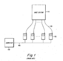
- Fig. 1 illustrates a typical prior art coaxial network testing system for use in simulating the air interface for test operations.
- a plurality of mobiles referred collectively by the reference numeral 100, are each connected to a base station 110 via individual coaxial cables 120. The connection is made by connecting one end of coaxial cable 120 to the antenna port of each of the mobiles and connecting the other end to base station 110.
- the cables provide individual shielded radio paths to and from each of the mobiles to the base station thus allowing a large number of mobiles to be conveniently tested from one location.
- very precise control of the signal strengths to and from the mobile can be achieved thereby providing suitable conditions for repeat testing.
- a computer 130 is connected via link 140 to each of the mobiles in order to automate the testing procedure and monitor and record the results.
- a disadvantage of using a coaxial network is that the same radio path is used for both the transmission and reception of signals thereby unrealistically isolating the mobile from signals from other mobiles i.e. co-channel interference. This is not suitable for testing problems arising from the interaction of signals from other mobiles such as mass traffic testing.
- Mass traffic testing includes testing the system during mass registrations and mass call setups by a large number of mobiles which better simulates real-life situations. This has become an area of growing importance since sustained high traffic conditions may lead to access collisions arising from a large number of mobiles attempting to simultaneously access a limited bandwidth channel. Thus a coaxial based network is unsuitable for this type of testing.
- a further desire is to provide a test environment that maintains consistent conditions which permit repeat testing.
- the invention discloses an indoor antenna test system for use in testing wireless telecommunication systems.
- the test system includes an antenna array comprising a plurality of individual antennas that are deployed in a predetermined and fixed pattern within a confined testing area such as a building or a laboratory.
- a plurality of base stations are connected to the antennas via an antenna matrix.
- the antenna matrix can be controlled by a computer workstation to automatically activate cells in a predetermined sequence according to a specified testing procedure.
- a mobile is preferably located in fixed position and operating within an activated cell such that test procedures are executed and monitored by a remote computer workstation.
- a plurality of operable mobiles may be included within the individual cells for tests involving mass traffic and/or interference.
- the present invention is particularly suitable for testing the air interface in a limited testing area by using real antennas that have the same propagation properties as those operating in the field. Furthermore, testing of handoff procedures and interference problems are readily achieved by appropriately shifting the active cell relative to the stationary mobile. Since all components can be stationary, the environmental conditions remain constant thereby permitting tests to be repeated for optimizing system parameters.
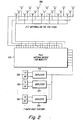
- Fig. 2 illustrates an exemplary embodiment of a test system operating in accordance with the present invention.
- a testing configuration comprising seven base stations, collectively referred to as reference numeral 200, that are connected to an array of twenty one antennas collectively referred to as 205.
- the configuration shown represents what is known in the art as a 7/21 cell plan and wherein the cell plan is indicative of the frequency reuse distance. It should be noted that the number of base stations and antennas i.e. cell plan used in the embodiment is arbitrary and can be appropriately scaled up or down to formulate a particular set of test conditions.
- the base stations 200 are represented as a transceiver (TX) and receiver (RX) and are coupled to a duplexer 215.
- the duplexer 215 separates the transmitted signals to and received signals from the antenna array 205. It will be understood by those skilled in the art that other detailed component blocks and devices of an operating test system are not shown in the exemplary illustration for purposes of simplification.
- the array of antennas 205 are deployed in a pattern suitable for use within a confined laboratory space or test area.
- the antennas 205 are distributed within the coverage area such that the distance from an arbitrary point within the coverage area to the nearest antenna is preferably in the range of 3-15 meters. It should be noted that this distance can also be varied of course to suit particular area constraints. Furthermore, the distribution of antennas is administered in accordance with the cell plan selected to generate the desired testing conditions.
- the base stations 200 and antennas 205 are coupled with leads to an antenna matrix 220 which completes the connection of the individual base stations to the antennas.
- the leads that couple the base stations and antennas to the antenna matrix 220 are typically shielded coaxial cables to provide suitable signal transmission and isolation.
- the matrix 220 can be a standard off-the-shelf RF cross connect matrix which functions by cross connecting at least one antenna with an associated base station at any given time by way of a linked computer workstation (not shown).
- Each antenna when connected to a base station, creates an active cell for use in testing the air interface with a suitable mobile.
- the activated cells can be controlled by a computer workstation, for example, to synchronize the timing of the activated cells for simulating movement of a stationary mobile. This aspect of mobility is easily achieved by the manipulation of activated cells by programming the workstation via the antenna matrix 220 such that the appropriate base stations and the associated antennas are connected in a predefined pattern.
- the overall space efficiency of the test system can be improved by the installation of the test components in separate locations, for example, the base stations may be located on a separate floor or room from the antennas.
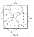
- Fig. 3 illustrates the concept of mobility as implemented under the present invention.
- a room is shown having twenty one antennas A1-A21 deployed in 7/21 cell plan in order to obtain the desired frequency reuse distance for testing.
- a predefined cell pattern reflecting the cell plan is present, i.e. every fifth antenna is active, A1, A6, A11 etc. their associated coverage areas represented by the circles 305, 310, and 315 respectively.
- a mobile 300 is placed in a fixed location within a cell, for example, in coverage area 305 of antenna A1 and linked to a computer for automated control and monitoring. Additional mobiles may be linked to the computer and placed in any of the other cell coverage areas as well.
- the mobile 300 can be operated alone within the cells or can be operated together with a plurality of mobiles for tests associated with mass traffic, for example.
- the movement of the stationary mobile is simulated by shifting the cell pattern in a step-wise manner such that each base station changes antenna to the adjacent antenna by means of the antenna matrix.
- a shift in the clockwise direction for example, is indicated by the arrows.
- the signal strength from the current connection i.e. first cell appears to weaken which the mobile interprets as a movement in its position.
- the received signal strength from the second cell becomes greater than from the first cell thereby inducing the mobile to initiate a handoff using standard handoff procedures. Therefore, a shift to the right in cell pattern represents a perceived movement to the mobile as a change in its position to the left.
- Fig. 4 shows a graph of the received signal strength of a mobile versus time.
- the signal strength received increases in stepwise manner until it reaches a peak, as represented by signal 410.
- the- signal strength decreases accordingly in steps at the same time as a second cell that is approaching the mobile, as represented by signal 420.
- the signal strength of the second cell then increases and becomes stronger than the signal strength from the first cell at t HO at which point a handoff occurs.
- the pattern repeats for the remaining cells until the first cell rotates back around again.
- the invention utilizing the shifting of cells with respect to a stationary mobile ensures a consistent handoff environment in which to conduct various and repeated tests. Accordingly, it becomes possible to perform system optimization by adjusting various system parameters under these constant test conditions.
- Additional tests can be readily implemented such as those involving a plurality of mobiles for testing interference on co-channels in cellular systems employing carrier frequency reuse plan in a plurality of cells.
- mobiles in different cells can be configured to operate on co-channels in order to investigate interference related issues.
- the frequency reuse distance may be chosen by forming different cell patterns conforming to 3/9, 4/12 etc. cell plans.
- Other types of testing using the present invention include interference driven channel selection, inter-MSC handoffs, traffic overload control, directed retry due to voice channel congestion, and base station power control issues, for example.
- the present invention contemplates a space-efficient test platform that provides a more realistic environment for testing the air interface. Since real antennas are used in the test process, handoff and interference problems from the field can be readily investigated in the laboratory. Furthermore, the intrinsic nature of the testing using stationary components provides for consistent environmental conditions that is particularly suitable for repeat testing. Hence repetition of identical tests enables fine tuning of the system by optimizing parameters and permits the evaluation of new functions and algorithms under the same conditions.
Landscapes
- Engineering & Computer Science (AREA)
- Computer Networks & Wireless Communication (AREA)
- Signal Processing (AREA)
- Physics & Mathematics (AREA)
- Electromagnetism (AREA)
- Mobile Radio Communication Systems (AREA)
- Air Conditioning Control Device (AREA)
- Selective Calling Equipment (AREA)
Abstract
Description
- The present invention relates generally to wireless telecommunication systems. More specifically, the invention relates to a system for testing wireless telecommunication systems using the air interface.
- In a basic cellular telecommunication system, a mobile switching center (MSC) is linked to a network of base stations by a series of digital transmission links. The base stations are geographically distributed to form an area of coverage for the system. Each base station is designated to cover a specified area, known as a cell, in which a two way radio communication can take place between a mobile station and the base station in the associated cell. The mobile station operating within a cell communicates with the base station over the air interface on a specified radio channel. For simplicity, the term mobile station will henceforth be referred to simply as the mobile.
- Manufacturers of wireless telecommunication equipment have long recognized the importance of testing the equipment prior to installation in the field. Many of the tests performed on the base station equipment and the mobile switching center (MSC) are typically well developed and do a good job of simulating real-life conditions. Other areas, such as those involving the air interface, have generally not been tested as rigorously, partly due to the inherent environmental randomness associated with the radio path thus leading to a lack of repeatability in testing procedures. For example, the actual environment a service provider operates in can contain a number of factors that are difficult to recreate in a test environment such as changing weather conditions, interfering signals, log normal and multi-path fading from obstacles and/or terrain etc. The precise conditions are often difficult to recreate in a laboratory back at the manufacturing site.
- A further complicating factor is that there is a limit to the amount and types of tests that can be performed at the installation site without significantly affecting current service. Since the environmental conditions at an operating site cannot be guaranteed to remain consistent, it may be difficult to compare results from repeated tests with much confidence. Thus the system reliability and robustness of the controlling software become difficult to verify from repeated testing where conditions need to be held constant.
- In prior testing methods, there have been attempts made to simulate the air interface in testing procedures in a laboratory environment. One example known in the art is to use a coaxial cable to connect the mobile to the base station to form a coaxial network air interface. This type of system has a number of disadvantages, notably that the isolated coaxial cables do not provide a suitable life-like radio path that is susceptible to any number of problematic elements as in an actual operating environment. A more detailed discussion of a coaxial network for simulating the air interface is described in U.S. Patent No. 5,465,393 granted to Frostrom et al. entitled: "Simulated Air Interface System for Simulating Radio Communication", issued on 11/07/95 to the present assignee and is incorporated by reference herein in its entirety.
- Fig. 1 illustrates a typical prior art coaxial network testing system for use in simulating the air interface for test operations. A plurality of mobiles, referred collectively by the
reference numeral 100, are each connected to abase station 110 via individualcoaxial cables 120. The connection is made by connecting one end ofcoaxial cable 120 to the antenna port of each of the mobiles and connecting the other end tobase station 110. The cables provide individual shielded radio paths to and from each of the mobiles to the base station thus allowing a large number of mobiles to be conveniently tested from one location. In addition, very precise control of the signal strengths to and from the mobile can be achieved thereby providing suitable conditions for repeat testing. Acomputer 130 is connected vialink 140 to each of the mobiles in order to automate the testing procedure and monitor and record the results. - A disadvantage of using a coaxial network is that the same radio path is used for both the transmission and reception of signals thereby unrealistically isolating the mobile from signals from other mobiles i.e. co-channel interference. This is not suitable for testing problems arising from the interaction of signals from other mobiles such as mass traffic testing. Mass traffic testing includes testing the system during mass registrations and mass call setups by a large number of mobiles which better simulates real-life situations. This has become an area of growing importance since sustained high traffic conditions may lead to access collisions arising from a large number of mobiles attempting to simultaneously access a limited bandwidth channel. Thus a coaxial based network is unsuitable for this type of testing.
- In view of the foregoing, it is desirable to provide a testing platform that more closely approximates real-life conditions with regards to the air interface. A further desire is to provide a test environment that maintains consistent conditions which permit repeat testing.
- Briefly described, and in accordance with an embodiment thereof, the invention discloses an indoor antenna test system for use in testing wireless telecommunication systems. In an embodiment of the present invention, the test system includes an antenna array comprising a plurality of individual antennas that are deployed in a predetermined and fixed pattern within a confined testing area such as a building or a laboratory. Further, a plurality of base stations are connected to the antennas via an antenna matrix. When the antenna matrix makes a connection between a base station and an antenna, a cell is activated accordingly. The antenna matrix can be controlled by a computer workstation to automatically activate cells in a predetermined sequence according to a specified testing procedure. A mobile is preferably located in fixed position and operating within an activated cell such that test procedures are executed and monitored by a remote computer workstation. Alternatively, a plurality of operable mobiles may be included within the individual cells for tests involving mass traffic and/or interference.
- The present invention is particularly suitable for testing the air interface in a limited testing area by using real antennas that have the same propagation properties as those operating in the field. Furthermore, testing of handoff procedures and interference problems are readily achieved by appropriately shifting the active cell relative to the stationary mobile. Since all components can be stationary, the environmental conditions remain constant thereby permitting tests to be repeated for optimizing system parameters. These and other advantages of the present invention will become apparent upon reading the following detailed description and studying the various figures of the drawings.
- The invention, together with further objects and advantages thereof, may best be understood by reference to the following description taken in conjunction with the accompanying drawings in which:
- Fig. 1 illustrates a prior art coaxial network testing system;
- Fig. 2 is an exemplary embodiment of an indoor antenna system operating in accordance with the present invention;
- Fig. 3 illustrates the present invention deployed in an exemplary indoor testing area; and
- Fig. 4 shows a graph of the received signal strength of a mobile versus time.
-
- Fig. 2 illustrates an exemplary embodiment of a test system operating in accordance with the present invention. Depicted is a testing configuration comprising seven base stations, collectively referred to as
reference numeral 200, that are connected to an array of twenty one antennas collectively referred to as 205. The configuration shown represents what is known in the art as a 7/21 cell plan and wherein the cell plan is indicative of the frequency reuse distance. It should be noted that the number of base stations and antennas i.e. cell plan used in the embodiment is arbitrary and can be appropriately scaled up or down to formulate a particular set of test conditions. Thebase stations 200 are represented as a transceiver (TX) and receiver (RX) and are coupled to aduplexer 215. Theduplexer 215 separates the transmitted signals to and received signals from theantenna array 205. It will be understood by those skilled in the art that other detailed component blocks and devices of an operating test system are not shown in the exemplary illustration for purposes of simplification. - The array of
antennas 205 are deployed in a pattern suitable for use within a confined laboratory space or test area. In the present embodiment, theantennas 205 are distributed within the coverage area such that the distance from an arbitrary point within the coverage area to the nearest antenna is preferably in the range of 3-15 meters. It should be noted that this distance can also be varied of course to suit particular area constraints. Furthermore, the distribution of antennas is administered in accordance with the cell plan selected to generate the desired testing conditions. Thebase stations 200 andantennas 205 are coupled with leads to anantenna matrix 220 which completes the connection of the individual base stations to the antennas. The leads that couple the base stations and antennas to theantenna matrix 220 are typically shielded coaxial cables to provide suitable signal transmission and isolation. In the embodiment, thematrix 220 can be a standard off-the-shelf RF cross connect matrix which functions by cross connecting at least one antenna with an associated base station at any given time by way of a linked computer workstation (not shown). - Each antenna, when connected to a base station, creates an active cell for use in testing the air interface with a suitable mobile. The activated cells can be controlled by a computer workstation, for example, to synchronize the timing of the activated cells for simulating movement of a stationary mobile. This aspect of mobility is easily achieved by the manipulation of activated cells by programming the workstation via the
antenna matrix 220 such that the appropriate base stations and the associated antennas are connected in a predefined pattern. In an alternative aspect of the embodiment, the overall space efficiency of the test system can be improved by the installation of the test components in separate locations, for example, the base stations may be located on a separate floor or room from the antennas. - Fig. 3 illustrates the concept of mobility as implemented under the present invention. A room is shown having twenty one antennas A1-A21 deployed in 7/21 cell plan in order to obtain the desired frequency reuse distance for testing. In a exemplary snapshot in time t0, a predefined cell pattern reflecting the cell plan is present, i.e. every fifth antenna is active, A1, A6, A11 etc. their associated coverage areas represented by the
circles coverage area 305 of antenna A1 and linked to a computer for automated control and monitoring. Additional mobiles may be linked to the computer and placed in any of the other cell coverage areas as well. Furthermore, the mobile 300 can be operated alone within the cells or can be operated together with a plurality of mobiles for tests associated with mass traffic, for example. - The movement of the stationary mobile is simulated by shifting the cell pattern in a step-wise manner such that each base station changes antenna to the adjacent antenna by means of the antenna matrix. A shift in the clockwise direction, for example, is indicated by the arrows. As the cell pattern rotates away from the stationary mobile, the signal strength from the current connection i.e. first cell appears to weaken which the mobile interprets as a movement in its position. When a second cell following the first cell rotates toward the stationary mobile, the received signal strength from the second cell becomes greater than from the first cell thereby inducing the mobile to initiate a handoff using standard handoff procedures. Therefore, a shift to the right in cell pattern represents a perceived movement to the mobile as a change in its position to the left.
- Fig. 4 shows a graph of the received signal strength of a mobile versus time. As a first cell approaches the mobile, the signal strength received increases in stepwise manner until it reaches a peak, as represented by
signal 410. As the first cell shifts away, the- signal strength decreases accordingly in steps at the same time as a second cell that is approaching the mobile, as represented bysignal 420. The signal strength of the second cell then increases and becomes stronger than the signal strength from the first cell at tHO at which point a handoff occurs. The pattern repeats for the remaining cells until the first cell rotates back around again. The invention utilizing the shifting of cells with respect to a stationary mobile ensures a consistent handoff environment in which to conduct various and repeated tests. Accordingly, it becomes possible to perform system optimization by adjusting various system parameters under these constant test conditions. - Additional tests can be readily implemented such as those involving a plurality of mobiles for testing interference on co-channels in cellular systems employing carrier frequency reuse plan in a plurality of cells. In these scenarios, mobiles in different cells can be configured to operate on co-channels in order to investigate interference related issues. By way of example, the frequency reuse distance may be chosen by forming different cell patterns conforming to 3/9, 4/12 etc. cell plans. Other types of testing using the present invention include interference driven channel selection, inter-MSC handoffs, traffic overload control, directed retry due to voice channel congestion, and base station power control issues, for example.
- The present invention contemplates a space-efficient test platform that provides a more realistic environment for testing the air interface. Since real antennas are used in the test process, handoff and interference problems from the field can be readily investigated in the laboratory. Furthermore, the intrinsic nature of the testing using stationary components provides for consistent environmental conditions that is particularly suitable for repeat testing. Hence repetition of identical tests enables fine tuning of the system by optimizing parameters and permits the evaluation of new functions and algorithms under the same conditions.
- While the invention has been described with reference to a specific embodiment, the description is illustrative of the inventive concept and is not to be construed as limiting to the invention. In particular, the inventive concept is also applicable to systems operating in accordance with Code Division Multiple Access (CDMA), for example. Various modifications and steps may occur to those skilled in the art without departing from the true spirit and scope of the invention as defined by the appended claims.
Claims (14)
- A test system for use in testing wireless telecommunication systems comprising:an antenna array comprising a plurality of individual antennas deployed in a fixed pattern within a testing area; characterized byan antenna matrix having a first and a second end, wherein the first end is connected to said antenna array;a plurality of base stations wherein each base station is connected to said second end of said antenna matrix;means for controlling said antenna matrix such that each of said plurality of base stations is selectively cross connected with an associated antenna; andat least one mobile located within communication range of one of said individual antennas.
- A test system according to claim 1 wherein said antenna matrix is controlled by a program running on a computer workstation such that the base stations cross connected to the associated antennas create a pattern of activated cells.
- A test system according to claim 1 wherein said individual antennas of the antenna array are deployed to provide the desired radio coverage of the test area.
- A test system according to claim 1 wherein said at least one mobile is located in a fixed position.
- A test system according to claim 2 wherein a plurality of mobiles are operated within one of said activated cells.
- A test system according to claim 5 wherein each of said plurality of mobiles are remotely controlled and monitored by a computer workstation.
- A method of testing a wireless telecommunication system, wherein the system having a plurality of base stations connected to a plurality of antennas via an antenna matrix, and wherein said antennas are deployed in a fixed pattern in a confined test area, and having at least one mobile located within the coverage area of at least one antenna, said method characterized by the steps of:activating a first cell by selectively connecting a first base station to a first antenna via the antenna matrix;initiating a test procedure for testing aspects of mobile communications;activating a second cell by connecting said first base station to a second antenna via the antenna matrix; andmonitoring and controlling the test procedure with a computer workstation.
- A method according to claim 7 wherein activating a cell further includes controlling the antenna matrix with a program from a computer workstation.
- A method according to claim 8 wherein the at least one mobile is placed in a fixed position.
- A method according to claim 9 wherein a first cell serving the stationary mobile shifts away from said at least one mobile, and wherein a second cell following the first cell approaches the mobile such that the received signal strength of the second cell becomes stronger than that from the first cell thereby inducing a handoff to the second cell.
- A method according to claim 7 wherein the testing procedure includes testing the air interface radio path for interference.
- A method according to claim 7 wherein the testing procedure includes testing the air interface for problems associated with mass traffic.
- A method according to claim 7 wherein the wireless telecommunication system is operating in accordance with a time division multiple standard such as digital advanced mobile phone system (D-AMPS).
- A method according to claim 7 wherein the wireless telecommunication system is operating in accordance with a code division multiple access (CDMA) standard.
Applications Claiming Priority (3)
| Application Number | Priority Date | Filing Date | Title |
|---|---|---|---|
| US09/195,671 US6308064B1 (en) | 1998-11-19 | 1998-11-19 | Air interface based wireless telecommunication test system |
| US195671 | 1998-11-19 | ||
| PCT/SE1999/002033 WO2000031895A1 (en) | 1998-11-19 | 1999-11-09 | Air interface based wireless telecommunication test system |
Publications (2)
| Publication Number | Publication Date |
|---|---|
| EP1131904A1 EP1131904A1 (en) | 2001-09-12 |
| EP1131904B1 true EP1131904B1 (en) | 2005-10-12 |
Family
ID=22722294
Family Applications (1)
| Application Number | Title | Priority Date | Filing Date |
|---|---|---|---|
| EP99958581A Expired - Lifetime EP1131904B1 (en) | 1998-11-19 | 1999-11-09 | Air interface based wireless telecommunication test system |
Country Status (8)
| Country | Link |
|---|---|
| US (1) | US6308064B1 (en) |
| EP (1) | EP1131904B1 (en) |
| AT (1) | ATE306754T1 (en) |
| AU (1) | AU1592000A (en) |
| BR (1) | BR9915490A (en) |
| CA (1) | CA2351494C (en) |
| DE (1) | DE69927702T2 (en) |
| WO (1) | WO2000031895A1 (en) |
Families Citing this family (20)
| Publication number | Priority date | Publication date | Assignee | Title |
|---|---|---|---|---|
| US6571082B1 (en) * | 1999-10-29 | 2003-05-27 | Verizon Laboratories Inc. | Wireless field test simulator |
| DE10040445C1 (en) * | 2000-08-18 | 2002-03-14 | Siemens Ag | Operating function testing method for mobile radio communications system simulates spatial distance between subscriber device and base station by varying base station transmission power |
| WO2002039545A1 (en) * | 2000-11-08 | 2002-05-16 | Telefonaktiebolaget Lm Ericsson (Publ) | Method and apparatus for testing with simulated moving mobile stations |
| JP2005519554A (en) * | 2002-03-04 | 2005-06-30 | アジムス ネットワークス インコーポレイテッド | Test system for simulating a wireless environment and method of use thereof |
| US20050053008A1 (en) * | 2002-03-04 | 2005-03-10 | Griesing John Robert | Wireless device isolation in a controlled RF test environment |
| US6724730B1 (en) * | 2002-03-04 | 2004-04-20 | Azimuth Networks, Inc. | Test system for simulating a wireless environment and method of using same |
| JP3845621B2 (en) * | 2003-03-24 | 2006-11-15 | アンリツ株式会社 | Mobile communication terminal test apparatus and mobile communication terminal test method |
| JP3913185B2 (en) * | 2003-03-24 | 2007-05-09 | アンリツ株式会社 | Mobile communication terminal test apparatus and mobile communication terminal test method |
| US7773985B2 (en) | 2003-09-22 | 2010-08-10 | United Parcel Service Of America, Inc. | Symbiotic system for testing electromagnetic signal coverage in areas near transport routes |
| US7660577B2 (en) * | 2003-09-22 | 2010-02-09 | United Parcel Service Of America, Inc. | Network testing systems and methods |
| US6903910B1 (en) | 2004-08-06 | 2005-06-07 | Azijuth Networks, Inc. | Shielded enclosure with user-installable interface modules |
| US7668530B2 (en) | 2005-04-01 | 2010-02-23 | Adaptix, Inc. | Systems and methods for coordinating the coverage and capacity of a wireless base station |
| US7593459B1 (en) | 2005-09-14 | 2009-09-22 | Redpine Signals, Inc. | Wireless link simulator |
| US7508868B2 (en) * | 2005-12-02 | 2009-03-24 | Kyocera Wireless Corp. | Systems and methods for testing the performance of and simulating a wireless communication device |
| JP4998133B2 (en) * | 2007-08-07 | 2012-08-15 | 富士通株式会社 | Mobile communication system and link establishment method |
| EP2043275B1 (en) * | 2007-09-25 | 2013-09-04 | ADTRAN GmbH | Method and device for noise processing and communication system comprising such device |
| US20110158340A1 (en) * | 2009-12-28 | 2011-06-30 | Qualcomm Incorporated | Virtual antenna array for wireless devices |
| CN102148648B (en) * | 2010-02-05 | 2015-04-01 | 中兴通讯股份有限公司 | Space radio-frequency performance test method and system in multi-antenna system |
| US9414224B1 (en) * | 2012-11-12 | 2016-08-09 | Sprint Communications Company L.P. | Antenna port identification |
| EP3035729A1 (en) * | 2014-12-18 | 2016-06-22 | Nokia Solutions and Networks Oy | Apparatus for testing RF communication equipment |
Family Cites Families (20)
| Publication number | Priority date | Publication date | Assignee | Title |
|---|---|---|---|---|
| US4225969A (en) * | 1979-01-31 | 1980-09-30 | International Business Machines Corporation | Method and apparatus for testing a frequency synthesizer in an RF modem |
| JPS5621435A (en) * | 1979-07-31 | 1981-02-27 | Nissan Motor Co Ltd | Extrahigh frequency transmitting and receiving device |
| JPH063886B2 (en) * | 1988-06-14 | 1994-01-12 | 富士通株式会社 | Folding test machine |
| JPH02312492A (en) * | 1989-05-29 | 1990-12-27 | Nec Corp | Channel assignment method in mobile communication system and learning system for base station arrangement information |
| US5095500A (en) * | 1989-12-07 | 1992-03-10 | Motorola, Inc. | Cellular radiotelephone diagnostic system |
| US5425076A (en) * | 1992-06-30 | 1995-06-13 | Minnesota Mining And Manufacturing Company | Cellular communications test system |
| US6038459A (en) * | 1992-10-19 | 2000-03-14 | Nortel Networks Corporation | Base station antenna arrangement |
| US5465393A (en) * | 1993-04-12 | 1995-11-07 | Telefonaktiebolaget Lm Ericsson | Simulated air interface system for simulating radio communication |
| GB2281012B (en) * | 1993-08-12 | 1998-04-15 | Northern Telecom Ltd | Angle diversity for multiple beam antenna |
| TW293968B (en) * | 1994-09-29 | 1996-12-21 | Radio Frequency Systems Inc | |
| US5861844A (en) * | 1994-11-29 | 1999-01-19 | Qualcomm Incorporated | Method and apparatus for providing redundant coverage within a cellular communication system |
| CA2164169A1 (en) | 1995-01-31 | 1996-08-01 | Sheldon Kent Meredith | Radio signal scanning and targeting system for use in land mobile radio base sites |
| US5794128A (en) * | 1995-09-20 | 1998-08-11 | The United States Of America As Represented By The Secretary Of The Army | Apparatus and processes for realistic simulation of wireless information transport systems |
| DE19618333A1 (en) * | 1996-05-07 | 1997-11-13 | Lindenmeier Heinz | Circuit arrangement for functional testing of mobile radio reception systems |
| US6023621A (en) * | 1996-06-28 | 2000-02-08 | Harris Corporation | Wireless communications system and method having dynamic reallocation of communication frequencies |
| DE19651334A1 (en) * | 1996-12-10 | 1998-06-25 | Ericsson Telefon Ab L M | Operational test device and method for executing an operational test for a system under test |
| GB2320618A (en) * | 1996-12-20 | 1998-06-24 | Northern Telecom Ltd | Base station antenna arrangement with narrow overlapping beams |
| US5946612A (en) * | 1997-03-28 | 1999-08-31 | Telefonaktiebolaget L M Ericsson (Publ) | Method and apparatus for performing local traffic measurements in a cellular telephone network |
| US6021315A (en) * | 1997-11-19 | 2000-02-01 | Cellular Technical Services Co., Inc. | System and method for testing of wireless communication devices |
| US5913638A (en) * | 1998-02-04 | 1999-06-22 | Lansdale; Michael Lee | Sand channel trenching and pipe laying apparatus |
-
1998
- 1998-11-19 US US09/195,671 patent/US6308064B1/en not_active Expired - Lifetime
-
1999
- 1999-11-09 WO PCT/SE1999/002033 patent/WO2000031895A1/en not_active Ceased
- 1999-11-09 AU AU15920/00A patent/AU1592000A/en not_active Abandoned
- 1999-11-09 AT AT99958581T patent/ATE306754T1/en not_active IP Right Cessation
- 1999-11-09 CA CA002351494A patent/CA2351494C/en not_active Expired - Fee Related
- 1999-11-09 DE DE69927702T patent/DE69927702T2/en not_active Expired - Lifetime
- 1999-11-09 EP EP99958581A patent/EP1131904B1/en not_active Expired - Lifetime
- 1999-11-09 BR BR9915490-0A patent/BR9915490A/en not_active Application Discontinuation
Also Published As
| Publication number | Publication date |
|---|---|
| BR9915490A (en) | 2001-07-31 |
| DE69927702T2 (en) | 2006-07-13 |
| AU1592000A (en) | 2000-06-13 |
| US6308064B1 (en) | 2001-10-23 |
| EP1131904A1 (en) | 2001-09-12 |
| ATE306754T1 (en) | 2005-10-15 |
| WO2000031895A1 (en) | 2000-06-02 |
| CA2351494C (en) | 2007-09-11 |
| CA2351494A1 (en) | 2000-06-02 |
| DE69927702D1 (en) | 2006-02-23 |
Similar Documents
| Publication | Publication Date | Title |
|---|---|---|
| US6308064B1 (en) | Air interface based wireless telecommunication test system | |
| US6052584A (en) | CDMA cellular system testing, analysis and optimization | |
| US5465393A (en) | Simulated air interface system for simulating radio communication | |
| EP2063676B1 (en) | Mobile-terminal simulator for a wireless telecommunications network | |
| US6272337B1 (en) | Testing a mobile communications system | |
| US6157838A (en) | Parallel optimization of wireless networks | |
| CN1336084A (en) | A wireless communication system that supports mobile test software agents | |
| EP2330843A1 (en) | Apparatus and method for providing a control signal | |
| US20020119772A1 (en) | Base station testing apparatus and method for testing a base station in a CDMA communication system | |
| US20070127559A1 (en) | Systems and methods for testing the performance of and simulating a wireless communication device | |
| CN102148649B (en) | Method and system for testing space radio frequency performance of multi-antenna device | |
| JP2012182834A (en) | System and method of adjusting coverage and capacity of wireless base station | |
| CN1282496A (en) | System and method for improving handoffs in cellular mobile radio systems | |
| EP3563497B1 (en) | Testing wireless networks using random wireless device locations | |
| US20230111045A1 (en) | Testing Method and Arrangement | |
| CN102104896A (en) | Mobile terminal test system and equipment | |
| CN113596936A (en) | Method, device, equipment and medium for switching beams in satellite communication system | |
| CN114268982B (en) | Vehicle-mounted mobile communication terminal test system | |
| KR100626996B1 (en) | Method for Making Downlink Behavior Measurements in a Wireless Communication System | |
| JP2011029877A (en) | Simulator for simulating communication environment | |
| Rosenberg | Simulation of power control and voice-channel selection in cellular systems | |
| KR100345027B1 (en) | Method and apparatus for measuring radio-wave | |
| JPH11220435A (en) | Wireless base station simulator | |
| WO2002039545A1 (en) | Method and apparatus for testing with simulated moving mobile stations | |
| WO2000038449A1 (en) | Radiocommunication test system with internet protocol addressed clusters |
Legal Events
| Date | Code | Title | Description |
|---|---|---|---|
| PUAI | Public reference made under article 153(3) epc to a published international application that has entered the european phase |
Free format text: ORIGINAL CODE: 0009012 |
|
| 17P | Request for examination filed |
Effective date: 20010618 |
|
| AK | Designated contracting states |
Kind code of ref document: A1 Designated state(s): AT BE CH CY DE DK ES FI FR GB GR IE IT LI LU MC NL PT SE |
|
| AX | Request for extension of the european patent |
Free format text: AL;LT;LV;MK;RO;SI |
|
| RAP1 | Party data changed (applicant data changed or rights of an application transferred) |
Owner name: TELEFONAKTIEBOLAGET LM ERICSSON (PUBL) |
|
| GRAP | Despatch of communication of intention to grant a patent |
Free format text: ORIGINAL CODE: EPIDOSNIGR1 |
|
| GRAS | Grant fee paid |
Free format text: ORIGINAL CODE: EPIDOSNIGR3 |
|
| GRAA | (expected) grant |
Free format text: ORIGINAL CODE: 0009210 |
|
| AK | Designated contracting states |
Kind code of ref document: B1 Designated state(s): AT BE CH CY DE DK ES FI FR GB GR IE IT LI LU MC NL PT SE |
|
| PG25 | Lapsed in a contracting state [announced via postgrant information from national office to epo] |
Ref country code: NL Free format text: LAPSE BECAUSE OF FAILURE TO SUBMIT A TRANSLATION OF THE DESCRIPTION OR TO PAY THE FEE WITHIN THE PRESCRIBED TIME-LIMIT Effective date: 20051012 Ref country code: LI Free format text: LAPSE BECAUSE OF FAILURE TO SUBMIT A TRANSLATION OF THE DESCRIPTION OR TO PAY THE FEE WITHIN THE PRESCRIBED TIME-LIMIT Effective date: 20051012 Ref country code: IT Free format text: LAPSE BECAUSE OF FAILURE TO SUBMIT A TRANSLATION OF THE DESCRIPTION OR TO PAY THE FEE WITHIN THE PRESCRIBED TIME-LIMIT;WARNING: LAPSES OF ITALIAN PATENTS WITH EFFECTIVE DATE BEFORE 2007 MAY HAVE OCCURRED AT ANY TIME BEFORE 2007. THE CORRECT EFFECTIVE DATE MAY BE DIFFERENT FROM THE ONE RECORDED. Effective date: 20051012 Ref country code: FI Free format text: LAPSE BECAUSE OF FAILURE TO SUBMIT A TRANSLATION OF THE DESCRIPTION OR TO PAY THE FEE WITHIN THE PRESCRIBED TIME-LIMIT Effective date: 20051012 Ref country code: CH Free format text: LAPSE BECAUSE OF FAILURE TO SUBMIT A TRANSLATION OF THE DESCRIPTION OR TO PAY THE FEE WITHIN THE PRESCRIBED TIME-LIMIT Effective date: 20051012 Ref country code: BE Free format text: LAPSE BECAUSE OF FAILURE TO SUBMIT A TRANSLATION OF THE DESCRIPTION OR TO PAY THE FEE WITHIN THE PRESCRIBED TIME-LIMIT Effective date: 20051012 Ref country code: AT Free format text: LAPSE BECAUSE OF FAILURE TO SUBMIT A TRANSLATION OF THE DESCRIPTION OR TO PAY THE FEE WITHIN THE PRESCRIBED TIME-LIMIT Effective date: 20051012 |
|
| REG | Reference to a national code |
Ref country code: GB Ref legal event code: FG4D |
|
| REG | Reference to a national code |
Ref country code: CH Ref legal event code: EP |
|
| REG | Reference to a national code |
Ref country code: IE Ref legal event code: FG4D |
|
| PG25 | Lapsed in a contracting state [announced via postgrant information from national office to epo] |
Ref country code: IE Free format text: LAPSE BECAUSE OF NON-PAYMENT OF DUE FEES Effective date: 20051109 Ref country code: CY Free format text: LAPSE BECAUSE OF FAILURE TO SUBMIT A TRANSLATION OF THE DESCRIPTION OR TO PAY THE FEE WITHIN THE PRESCRIBED TIME-LIMIT Effective date: 20051109 |
|
| PG25 | Lapsed in a contracting state [announced via postgrant information from national office to epo] |
Ref country code: MC Free format text: LAPSE BECAUSE OF NON-PAYMENT OF DUE FEES Effective date: 20051130 |
|
| PG25 | Lapsed in a contracting state [announced via postgrant information from national office to epo] |
Ref country code: LU Free format text: LAPSE BECAUSE OF NON-PAYMENT OF DUE FEES Effective date: 20051212 |
|
| PG25 | Lapsed in a contracting state [announced via postgrant information from national office to epo] |
Ref country code: SE Free format text: LAPSE BECAUSE OF FAILURE TO SUBMIT A TRANSLATION OF THE DESCRIPTION OR TO PAY THE FEE WITHIN THE PRESCRIBED TIME-LIMIT Effective date: 20060112 Ref country code: GR Free format text: LAPSE BECAUSE OF FAILURE TO SUBMIT A TRANSLATION OF THE DESCRIPTION OR TO PAY THE FEE WITHIN THE PRESCRIBED TIME-LIMIT Effective date: 20060112 Ref country code: DK Free format text: LAPSE BECAUSE OF FAILURE TO SUBMIT A TRANSLATION OF THE DESCRIPTION OR TO PAY THE FEE WITHIN THE PRESCRIBED TIME-LIMIT Effective date: 20060112 |
|
| PG25 | Lapsed in a contracting state [announced via postgrant information from national office to epo] |
Ref country code: ES Free format text: LAPSE BECAUSE OF FAILURE TO SUBMIT A TRANSLATION OF THE DESCRIPTION OR TO PAY THE FEE WITHIN THE PRESCRIBED TIME-LIMIT Effective date: 20060123 |
|
| REF | Corresponds to: |
Ref document number: 69927702 Country of ref document: DE Date of ref document: 20060223 Kind code of ref document: P |
|
| PG25 | Lapsed in a contracting state [announced via postgrant information from national office to epo] |
Ref country code: PT Free format text: LAPSE BECAUSE OF FAILURE TO SUBMIT A TRANSLATION OF THE DESCRIPTION OR TO PAY THE FEE WITHIN THE PRESCRIBED TIME-LIMIT Effective date: 20060313 |
|
| NLV1 | Nl: lapsed or annulled due to failure to fulfill the requirements of art. 29p and 29m of the patents act | ||
| REG | Reference to a national code |
Ref country code: CH Ref legal event code: PL |
|
| PLBE | No opposition filed within time limit |
Free format text: ORIGINAL CODE: 0009261 |
|
| STAA | Information on the status of an ep patent application or granted ep patent |
Free format text: STATUS: NO OPPOSITION FILED WITHIN TIME LIMIT |
|
| REG | Reference to a national code |
Ref country code: IE Ref legal event code: MM4A |
|
| 26N | No opposition filed |
Effective date: 20060713 |
|
| PG25 | Lapsed in a contracting state [announced via postgrant information from national office to epo] |
Ref country code: FR Free format text: LAPSE BECAUSE OF FAILURE TO SUBMIT A TRANSLATION OF THE DESCRIPTION OR TO PAY THE FEE WITHIN THE PRESCRIBED TIME-LIMIT Effective date: 20061020 |
|
| EN | Fr: translation not filed | ||
| PG25 | Lapsed in a contracting state [announced via postgrant information from national office to epo] |
Ref country code: FR Free format text: LAPSE BECAUSE OF FAILURE TO SUBMIT A TRANSLATION OF THE DESCRIPTION OR TO PAY THE FEE WITHIN THE PRESCRIBED TIME-LIMIT Effective date: 20051130 |
|
| PG25 | Lapsed in a contracting state [announced via postgrant information from national office to epo] |
Ref country code: FR Free format text: LAPSE BECAUSE OF FAILURE TO SUBMIT A TRANSLATION OF THE DESCRIPTION OR TO PAY THE FEE WITHIN THE PRESCRIBED TIME-LIMIT Effective date: 20051012 |
|
| PGFP | Annual fee paid to national office [announced via postgrant information from national office to epo] |
Ref country code: GB Payment date: 20131127 Year of fee payment: 15 Ref country code: DE Payment date: 20131127 Year of fee payment: 15 |
|
| REG | Reference to a national code |
Ref country code: DE Ref legal event code: R119 Ref document number: 69927702 Country of ref document: DE |
|
| GBPC | Gb: european patent ceased through non-payment of renewal fee |
Effective date: 20141109 |
|
| PG25 | Lapsed in a contracting state [announced via postgrant information from national office to epo] |
Ref country code: GB Free format text: LAPSE BECAUSE OF NON-PAYMENT OF DUE FEES Effective date: 20141109 Ref country code: DE Free format text: LAPSE BECAUSE OF NON-PAYMENT OF DUE FEES Effective date: 20150602 |