EP1131577B1 - Multi-layer conduit - Google Patents
Multi-layer conduit Download PDFInfo
- Publication number
- EP1131577B1 EP1131577B1 EP99972296A EP99972296A EP1131577B1 EP 1131577 B1 EP1131577 B1 EP 1131577B1 EP 99972296 A EP99972296 A EP 99972296A EP 99972296 A EP99972296 A EP 99972296A EP 1131577 B1 EP1131577 B1 EP 1131577B1
- Authority
- EP
- European Patent Office
- Prior art keywords
- conduit
- layer
- tab
- high density
- density polyethylene
- Prior art date
- Legal status (The legal status is an assumption and is not a legal conclusion. Google has not performed a legal analysis and makes no representation as to the accuracy of the status listed.)
- Expired - Lifetime
Links
- 239000000463 material Substances 0.000 claims description 60
- 239000000945 filler Substances 0.000 claims description 47
- 239000000446 fuel Substances 0.000 claims description 46
- 230000004888 barrier function Effects 0.000 claims description 44
- 229920001903 high density polyethylene Polymers 0.000 claims description 36
- 239000004700 high-density polyethylene Substances 0.000 claims description 36
- 239000000853 adhesive Substances 0.000 claims description 16
- 230000001070 adhesive effect Effects 0.000 claims description 16
- 229920000219 Ethylene vinyl alcohol Polymers 0.000 claims description 14
- 229930195733 hydrocarbon Natural products 0.000 claims description 14
- 150000002430 hydrocarbons Chemical class 0.000 claims description 14
- 238000000034 method Methods 0.000 claims description 13
- 239000004215 Carbon black (E152) Substances 0.000 claims description 11
- 230000008569 process Effects 0.000 claims description 11
- 238000007664 blowing Methods 0.000 claims description 6
- 238000004519 manufacturing process Methods 0.000 claims description 4
- 239000000203 mixture Substances 0.000 claims description 4
- 239000004687 Nylon copolymer Substances 0.000 claims description 3
- 239000008188 pellet Substances 0.000 claims description 2
- 230000002401 inhibitory effect Effects 0.000 claims 1
- 239000010410 layer Substances 0.000 description 119
- 230000003068 static effect Effects 0.000 description 21
- 230000005611 electricity Effects 0.000 description 19
- 239000002828 fuel tank Substances 0.000 description 12
- 239000004715 ethylene vinyl alcohol Substances 0.000 description 11
- 229920005989 resin Polymers 0.000 description 11
- 239000011347 resin Substances 0.000 description 11
- 229920003023 plastic Polymers 0.000 description 10
- 239000004033 plastic Substances 0.000 description 10
- 238000000465 moulding Methods 0.000 description 7
- 241001312297 Selar Species 0.000 description 6
- 229920003365 Selar® Polymers 0.000 description 6
- 238000000071 blow moulding Methods 0.000 description 6
- 239000004020 conductor Substances 0.000 description 6
- 238000001125 extrusion Methods 0.000 description 6
- OKTJSMMVPCPJKN-UHFFFAOYSA-N Carbon Chemical compound [C] OKTJSMMVPCPJKN-UHFFFAOYSA-N 0.000 description 5
- 238000011049 filling Methods 0.000 description 5
- 239000003502 gasoline Substances 0.000 description 5
- 239000002184 metal Substances 0.000 description 5
- 229910052751 metal Inorganic materials 0.000 description 5
- 238000003860 storage Methods 0.000 description 5
- 239000012790 adhesive layer Substances 0.000 description 4
- 239000006229 carbon black Substances 0.000 description 4
- VGGSQFUCUMXWEO-UHFFFAOYSA-N Ethene Chemical compound C=C VGGSQFUCUMXWEO-UHFFFAOYSA-N 0.000 description 3
- 239000005977 Ethylene Substances 0.000 description 3
- 239000004677 Nylon Substances 0.000 description 3
- 239000012530 fluid Substances 0.000 description 3
- 239000007788 liquid Substances 0.000 description 3
- 229920001778 nylon Polymers 0.000 description 3
- -1 polyethylene Polymers 0.000 description 3
- 229920001470 polyketone Polymers 0.000 description 3
- 239000004952 Polyamide Substances 0.000 description 2
- 239000004698 Polyethylene Substances 0.000 description 2
- 238000007792 addition Methods 0.000 description 2
- 239000000654 additive Substances 0.000 description 2
- 238000002485 combustion reaction Methods 0.000 description 2
- 238000001816 cooling Methods 0.000 description 2
- 229920001577 copolymer Polymers 0.000 description 2
- 230000001419 dependent effect Effects 0.000 description 2
- 238000004880 explosion Methods 0.000 description 2
- 230000002093 peripheral effect Effects 0.000 description 2
- 229920002647 polyamide Polymers 0.000 description 2
- 229920000573 polyethylene Polymers 0.000 description 2
- 239000012815 thermoplastic material Substances 0.000 description 2
- 238000003466 welding Methods 0.000 description 2
- 229920003313 Bynel® Polymers 0.000 description 1
- 229920013687 Carilon Polymers 0.000 description 1
- 239000004743 Polypropylene Substances 0.000 description 1
- 230000008901 benefit Effects 0.000 description 1
- 230000005540 biological transmission Effects 0.000 description 1
- 230000015572 biosynthetic process Effects 0.000 description 1
- 230000000740 bleeding effect Effects 0.000 description 1
- 239000003795 chemical substances by application Substances 0.000 description 1
- 239000011248 coating agent Substances 0.000 description 1
- 238000000576 coating method Methods 0.000 description 1
- 230000008878 coupling Effects 0.000 description 1
- 238000010168 coupling process Methods 0.000 description 1
- 238000005859 coupling reaction Methods 0.000 description 1
- 239000003814 drug Substances 0.000 description 1
- 229940079593 drug Drugs 0.000 description 1
- 230000000694 effects Effects 0.000 description 1
- 239000002360 explosive Substances 0.000 description 1
- 239000003063 flame retardant Substances 0.000 description 1
- 238000009472 formulation Methods 0.000 description 1
- 230000004927 fusion Effects 0.000 description 1
- 238000010438 heat treatment Methods 0.000 description 1
- 238000009434 installation Methods 0.000 description 1
- 239000000155 melt Substances 0.000 description 1
- 150000002739 metals Chemical class 0.000 description 1
- 230000008520 organization Effects 0.000 description 1
- 239000003348 petrochemical agent Substances 0.000 description 1
- 229920006122 polyamide resin Polymers 0.000 description 1
- 229920000642 polymer Polymers 0.000 description 1
- 239000013047 polymeric layer Substances 0.000 description 1
- 239000002952 polymeric resin Substances 0.000 description 1
- 229920001155 polypropylene Polymers 0.000 description 1
- 230000002250 progressing effect Effects 0.000 description 1
- 238000004064 recycling Methods 0.000 description 1
- 238000007493 shaping process Methods 0.000 description 1
- 229920003002 synthetic resin Polymers 0.000 description 1
- 229920001169 thermoplastic Polymers 0.000 description 1
- 239000004416 thermosoftening plastic Substances 0.000 description 1
- 239000002699 waste material Substances 0.000 description 1
Images

Classifications
-
- F—MECHANICAL ENGINEERING; LIGHTING; HEATING; WEAPONS; BLASTING
- F16—ENGINEERING ELEMENTS AND UNITS; GENERAL MEASURES FOR PRODUCING AND MAINTAINING EFFECTIVE FUNCTIONING OF MACHINES OR INSTALLATIONS; THERMAL INSULATION IN GENERAL
- F16L—PIPES; JOINTS OR FITTINGS FOR PIPES; SUPPORTS FOR PIPES, CABLES OR PROTECTIVE TUBING; MEANS FOR THERMAL INSULATION IN GENERAL
- F16L11/00—Hoses, i.e. flexible pipes
- F16L11/04—Hoses, i.e. flexible pipes made of rubber or flexible plastics
- F16L11/12—Hoses, i.e. flexible pipes made of rubber or flexible plastics with arrangements for particular purposes, e.g. specially profiled, with protecting layer, heated, electrically conducting
- F16L11/127—Hoses, i.e. flexible pipes made of rubber or flexible plastics with arrangements for particular purposes, e.g. specially profiled, with protecting layer, heated, electrically conducting electrically conducting
-
- B—PERFORMING OPERATIONS; TRANSPORTING
- B29—WORKING OF PLASTICS; WORKING OF SUBSTANCES IN A PLASTIC STATE IN GENERAL
- B29C—SHAPING OR JOINING OF PLASTICS; SHAPING OF MATERIAL IN A PLASTIC STATE, NOT OTHERWISE PROVIDED FOR; AFTER-TREATMENT OF THE SHAPED PRODUCTS, e.g. REPAIRING
- B29C49/00—Blow-moulding, i.e. blowing a preform or parison to a desired shape within a mould; Apparatus therefor
- B29C49/22—Blow-moulding, i.e. blowing a preform or parison to a desired shape within a mould; Apparatus therefor using multilayered preforms or parisons
-
- B—PERFORMING OPERATIONS; TRANSPORTING
- B60—VEHICLES IN GENERAL
- B60K—ARRANGEMENT OR MOUNTING OF PROPULSION UNITS OR OF TRANSMISSIONS IN VEHICLES; ARRANGEMENT OR MOUNTING OF PLURAL DIVERSE PRIME-MOVERS IN VEHICLES; AUXILIARY DRIVES FOR VEHICLES; INSTRUMENTATION OR DASHBOARDS FOR VEHICLES; ARRANGEMENTS IN CONNECTION WITH COOLING, AIR INTAKE, GAS EXHAUST OR FUEL SUPPLY OF PROPULSION UNITS IN VEHICLES
- B60K15/00—Arrangement in connection with fuel supply of combustion engines or other fuel consuming energy converters, e.g. fuel cells; Mounting or construction of fuel tanks
- B60K15/03—Fuel tanks
- B60K15/04—Tank inlets
-
- F—MECHANICAL ENGINEERING; LIGHTING; HEATING; WEAPONS; BLASTING
- F16—ENGINEERING ELEMENTS AND UNITS; GENERAL MEASURES FOR PRODUCING AND MAINTAINING EFFECTIVE FUNCTIONING OF MACHINES OR INSTALLATIONS; THERMAL INSULATION IN GENERAL
- F16L—PIPES; JOINTS OR FITTINGS FOR PIPES; SUPPORTS FOR PIPES, CABLES OR PROTECTIVE TUBING; MEANS FOR THERMAL INSULATION IN GENERAL
- F16L11/00—Hoses, i.e. flexible pipes
- F16L11/04—Hoses, i.e. flexible pipes made of rubber or flexible plastics
- F16L2011/047—Hoses, i.e. flexible pipes made of rubber or flexible plastics with a diffusion barrier layer
Definitions
- This invention relates generally to multi-layered laminate structures which may be used to handle volatile, explosive liquids.
- the invention relates to a multi-layered laminated structure useful as a filler pipe for adding hydrocarbon containing fluids such as gasoline to a storage tank as may be carried in a vehicle having an internal combustion engine.
- Hydrocarbon containing fluids such as gasoline are the most common power source for internal combustion engines.
- Gasoline must be carried by the vehicle, usually in a fuel tank.
- the fuel tank is located at some convenient location within the structure of the vehicle. Often the fuel tank is contained within a reinforced area so as to provide crash protection for the fuel tank.
- the vehicle In order to provide a convenient access to the tank, the vehicle is typically fitted with a fuel filler inlet. Thus, there is required a conduit to extend between the fuel filler inlet and the tank. That conduct may be long or short and may be of convoluted configuration depending upon the relative location of the tank and the filler inlet.
- the fuel filler conduit must contain at least one layer to substantially inhibit, if not totally prevent, passage of vapours from the liquid fuel to ambient atmosphere outside the filler pipe.
- Static electricity in fuel storage systems is dependent primarily on the rate of fill, the amount of turbulence in the fuel as it passes along the conduit and the amount of charge present in the fuel before contacting the vehicle. As fuel is passed along the conduit there is a good likelihood that a static electricity charge will build up. If that charge is permitted to increase until a spark is generated there is a danger of explosion of fuel vapours. Such explosions can be catastrophic not only to the fuel system but the entire vehicle and those in the vicinity of the vehicle.
- the part of the filler head which touches the refuelling nozzle is made of a conductive material and that is connected directly to the vehicle ground. This effectively prevents a difference in electrical potential between the refuelling nozzle and the filler head and the vehicle. Thus, there is no spark discharge.
- a plastic fuel filler pipe is desired, because of the normal insulative value of most plastic resins, there will be no readily available way to bleed off or ground the static electricity which may be built up along the filler pipe itself.
- fuel filler pipes when made of plastic be capable of being joined to related structure. At one end this means connection to the tank. At the other end this conduit will be joined to a filler coupling.
- Such connection at one or both ends may be made by welding, particularly where two similar thermoplastic materials are involved. Such welding is commonly done by raising the temperature of the two surfaces to be joined and then bringing the two molten surfaces into contact to enable fusion to occur as cooling occurs.
- Connections may also be required or desired at points along the conduit and it may be especially desirable that one or more of such connections are electrically connected to assist in bleeding off static electricity.
- a fuel filler conduit which may be economically manufactured from plastic resins which inhibits the passage of vapours through the conduit to the surrounding atmosphere and which at the same time provides an electrically conductive path sufficient to prevent the build up of static electricity by fuel passing along the conduit.
- a multi-layer conduit as defined in claim 1, and a process as defined in the independent claim 13, are provided.
- the layers include an inner layer which is comprised of electrically conductive high density polyethylene based material.
- the layers also include a barrier material which acts as a barrier to reduce passage of hydrocarbons through the walls of the conduit.
- the layers include an inner layer which is comprised of electrically conductive high density polyethylene based material.
- the conduit also includes an outer layer comprised of high density polyethylene.
- the conduit further includes a barrier layer of ethylene vinyl alcohol copolymer (EVOH) and two layers of adhesive, one on either side of the EVOH barrier layer for the purpose of bonding the EVOH layer to layers which are radially adjacent to the barrier layer.
- EVOH ethylene vinyl alcohol copolymer
- scrap regrind polyethylene based material may be used next to the conductive layer.
- the first two layers comprise at least 50% of the weight per unit length of the conduit.
- the conduit may be made from two layers, a radially inward layer which will be in contact with hydrocarbon fuel passing along the conduit which is electrically conductive high density polyethylene based material and a second, outward layer comprising Dupont SELAR, a blend of nylon copolymer, a proprietary adhesive for nylon and a high density polyethylene.
- a filler conduit preferably incudes at least one tab for structurally attaching the conduit to a vehicle.
- the tab is located between the ends of the conduit and includes an electrically conductive portion for contacting a fastener. A portion of the tab is electrically conductive. This portion of the tab is electrically connected to the inner, electrically conductive layer of the conduit to assist in conducting static electricity.
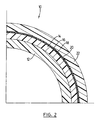
- the multi-layer conduit of the embodiment shown in Figures 1 and 2 at 10 comprises a plurality of layers. As shown in Figure 2, the conduit comprises six layers commencing at the radially innermost layer 12 and progressing outwardly through layers 14, 16, 18, 20 and 22.
- the inner layer 12 is made from electrically conductive, high density, polyethylene.
- the next adjacent layer 14 is made from high density polyethylene material which may be either virgin material or scrap material as will be discussed more fully hereinafter.
- the conduit includes a barrier layer 18 which is bonded to the adjacent layers by a layer of adhesive 16 on the radially inner surface and a layer of adhesive 20 on the radially outer surface.
- the outermost layer 22 is a layer of high density polyethylene.
- the barrier layer 18 is made of ethylene, vinyl alcohol copolymer (EVOH).
- the barrier layer of ethylene, vinyl alcohol copolymer serves as a barrier for passage of gaseous hydrocarbons which are a typical components of fuels.
- the EVOH product is available from a number of suppliers. One such product is identified by the trade mark LC-101A and is available from Eval Company of America.
- the product is 27 mole percent ethylene and is sold as a high barrier resin for multi-layer barrier structures. This resin is said by its manufacturer to be the highest gas barrier EVOH material available. According to the manufacturer's specification, the resin may be used as an interior barrier layer of a multi-layer food package as outlined by the U.S.
- the EVOH layer is separated from direct food contact by a polymeric layer at least 1 ml thick. It has been found that this resin produces a suitable barrier to prevent transmission of hydrocarbon vapours typical of those found in fuels such as gasoline through the fuel filler conduit manufactured in accordance with this preferred embodiment of the invention.
- adhesives 16 and 20 are used on the inner and outer surfaces of the barrier layer 18 respectively.
- a suitable adhesive for use in adhering the EVOH layer is the adhesive sold under the trade mark ADMER by Mitsui Petrochemicals (America) Ltd. This adhesive is sold for adhering the layer EVOH film to high density polyethylene or adhering high density polyethylene to nylon.
- the conduit has high density polyethylene next to both surfaces of the barrier layer and thus the same adhesive can be used on each surface of the barrier layer 16.
- the inner layer 12 will be in contact with fuel passing along the conduit. Thus, static electricity is likely to be generated at the inner surface of the inner layer 12.
- the static electric may be present in the fuel from its remote storage or may be generated by the passage of the fuel along the conduit.
- the amount of static electricity that will be generated may be dependent upon the configuration of the conduit which, in turn, may promote turbulence.
- the quality of the surface finish of the conduit may also be a factor in generating turbulence and thus generation of static electricity.
- the inner layer 12 is made suitably electrically conductive to dissipate static electricity thus preventing the build up of sufficient charge to cause sparks.
- High density polyethylene may be made sufficiently conductive by including within the resin, carbon black.
- carbon black sold under the trade mark PRINTEX XE 2 by Degussa AG of Frankfurt, Germany. Addition of carbon black, such as PRINTEX XE 2, into high density polyethylene produces a significant drop in the resistance of the polymer to electric current at relatively low concentration. According to the manufacturer of PRINTEX XE 2, only approximately 1/3 to 1/4 of the amount of conventional carbon black need be added to a polymeric resin to generate suitable conductivity for anti-static suitability of the resulting mixed resin. By way of example, the manufacturer suggests that additions of about 5 - 15% of PRINTEX XE 2 are sufficient to achieve conductivity values in the area of ⁇ 10 2 ohm x cm in thermoplastics.
- scrap high density polyethylene As will be well understood by those familiar with the blow molding art, there are often scrap or flash materials which must be removed from finished products. The non-use of that scrap material represents a cost. This product provides an opportunity to make use of what would otherwise would be waste high density polyethylene material. The material is reground and fed to the melt and extrusion process for use in the layer 14 of the conduit 10. The adjacent layer 14 thus may be made from virgin, high density polyethylene or scrap regrind material from this multi-layer conduit or scrap regrind, high density polyethylene, or combinations of the foregoing.
- the outer layer 22 is preferably manufactured from virgin, high density polyethylene.
- the layers are made at varying thicknesses.
- the thicknesses depend in part on the diameter of the conduit. Thus the values given below are given in weight percent terms of the over all unit length of conduit.
- the internal layer 12 may comprise approximately 20% by weight conductive high density polyethylene.
- the next layer 14 may comprise about 40% by weight of the material or combination of materials discussed above.
- the barrier layer 18 of EVOH material may comprise approximately 3% by weight of the conduit.
- Each adhesive layer 16, 20 on either side of the barrier layer 16 may comprise approximately 3% by weight of the conduit.
- the outermost layer 22 of virgin high density polyethylene material may comprise approximately 37% by weight of the conduit.
- the combination of the innermost layers 12 and 14 together comprise at least 50% and preferably 60% of the weight of the conduit.
- This provides substantial weldable material at the inner surface of the multi-layer conduit.
- the material may most advantageously be joined by forming welds of the thermoplastic material.
- welds are achieved by heating the surrounding material to which the conduit is to be joined as well as the multi-layer conduit to a molten condition. The two materials are then brought into contact under pressure so that the material from the multi-layer conduit may fuse together with the material to which the multi-layer conduit is to be joined. It has been observed that appropriate welds can be made most easily if the combination of layers 12 and 14 are of weldable material and together comprise at least 50% of the weight of the conduit. This has been observed to provide high quality acceptable welds.
- the conduit may be handled roughly after its manufacture in transit to the installation where the conduit is to be fixed to a tank or to a vehicle. It is thus desirable that the exterior material has substantial impact resistance. This impact resistance may also be of considerable value once the fuel filler is installed on a vehicle to help resist failure of the fuel filler during the life of the vehicle.
- the outer layer 22 be manufactured from virgin, high density polyethylene material. The virgin material will thus have predictable impact strength which would otherwise be somewhat variable if it were mixed with scrap material. Virgin, high density polyethylene material advantageously provides suitable impact resistance for this structure.
- a multi-layer pipe of this invention may be manufactured in a multiple layer co-extrusion die.
- Such devices are available from companies such as Nextrom.
- Nextrom manufactures a die comprising different inputs each arranged concentrically to co-extrude a first, radially inner, layer and to co-extrude a plurality of layers radially adjacent thereto.
- the inner layer 12 would be extruded using a first channel.
- the next layer 14 is extruded in the same die at the same time as the other of the layers through an annular opening which is slightly downstream in the extruder from the opening extruding the layer 12. This effectively extrudes a tubular layer of material over the material which is to become the inner layer 12.
- the next layer extruded is the adhesive layer 16 followed by the EVOH barrier layer 18, followed by the adhesive layer 20 and then by the outer layer 22.
- a multi-layer parison is formed of the extruded material.
- the parison may then be placed in a blow mold cavity. Air pressure is introduced internally of the parison to mold the parison to a desired configuration for the fuel filler conduit. On cooling of the blown resin, the mold is opened to reveal the finished part. Any flash is then removed to form the finished product.
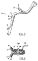
- Each of the filler conduits shown in Figures 1 and 5 include a tab.
- the tab 30 is located between the first and second ends of the filler conduit.
- the tab may be used to attach the fuel filler pipe to a frame, body component or other supporting structure which will give support to the fuel filler conduit intermediate the ends.
- One or more of such tabs 30 may be molded as desired.
- the tab 30 comprises a central web 32 and a peripheral edge 34.
- the tab 30 further comprises a metallic plate 36 more clearly shown in Figure 4.
- the attachment point As the tab will be used to attach the filler pipe to a portion of the vehicle body or frame, it is desirable that the attachment point also be part of the conductive path to dissipate static electricity.
- the tab is used by passing the fastener which itself is a conductor of electricity, through the web 32 of the tab and through the metallic plate 36.
- the metallic plate 36 is in contact with the inner conductive layer 12 of the parison material.
- static electricity building up along the interior surface of the conduit 10 can travel along the conductive layer 12 into the plate 36 and from the plate 36 to the fastener.
- the fastener is then connected to a grounded portion of the body to provide yet another path for discharge of static electricity being built up by passage of fluid along the conduit.
- the tab 30 may be formed during the blow molding process.
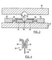
- Figure 3 illustrates the portion of the mold for shaping the multi-layer conduit at the location of the tab 30.
- the mold is shown as having upper and lower mold halfs. However, the molding of the filler conduit may occur with mold closure either vertically or horizontally.
- the mold comprises a first member or half 40 and a second complimentary member or half 42. At all locations other than the vicinity of a tab, the mold halves 40 and 42 close together to comprise a shape which is substantially circular in cross-section to define the exterior configuration of the filler conduit.
- the mold is cut away in the desired vicinity of the tab. At the cut away portion, the mold half 42 is equipped with slides 44 and 46.
- the slides 44 and 46 move horizontally left and right from the closed position shown in Figure 3 to an open position.
- the slides 44 and 46 are respectively attached to threaded rods 48 and 50.
- the threaded rods 48 and 50 are in turn fixed to a hydraulic piston illustrated diagrammatically as blocks 52 and 54 respectively. Movement within the hydraulic blocks 52 and 54 moves the slides 44 and 46 laterally as illustrated in Figure 3.
- slide 44 comprises a projection 56 which projects toward the slide 46.
- the molding face of the slides 44 and 46 respectively include the substantially quarter circular surfaces 60 and 62 as well as the planar surfaces 64 and 66.
- the conduit 10 and the integral tab 30 may be produced at the same time.
- a parison is extruded between the mold halves 40 and 42. If the parison is extruded vertically then the mold halves 40 and 42 may close substantially horizontally. If the mold halves 40 and 42 are horizontally arranged as shown in Figure 3 for convenience, then the parison after extrusion would have to be placed between the mold halves 40 and 42.
- the mold halves 40 and 42 are enclosed about the parison with the slides 44 and 46 in the open position. Blowing gas is then admitted to the interior of the parison in typical blow molding fashion. This will expand the parison against the molding surface of mold half 40 and against the molding surface of the slides 44 and 46.
- the next step in the process is the closure of the slides 44 and 46.
- the slides are moved inwardly to the position shown in Figure 3. This effectively pinches the portion of the parison creating the final configuration of the exterior surface of the filler conduit.
- the projection 56 further pinches the parison wall as shown in Figure 4.
- the pinch is identified as portion 68 in Figure 4. It will be observed that the pinch formed by the projection 56 leaves the two interior surfaces of the parison opposite the projection 56 in substantial contact with one another.
- blowing gas under pressure is again administered to the interior of the parison to form the final interior configuration of the interior of the parison.
- the part is then allowed to cool, the mold is then opened and the part removed from the mold.
- the periphery of the tab 30 adjacent the edge 34 is then cut by a knife leaving an open surface.
- the metallic plate 36 is then passed into the open surface between the edges 34 in the wall of the tab 30.
- the plate 36 is passed into the tab and between the pinched portion of the parison opposite the portion 68 ensuring that the plate 36 is in good electrical contact with the conductive inner layer of the formed filler pipe, the pinched portion of the parison serves to retain the plate 36 under friction until such time as a fastener is passed through the tab.
- the fastener may be passed through the tab by starting the point of the fastener in the portion 68 shown in Figure 4. This ensures that the fastener itself will be in good electrical contact with the plate 36 as well as both inner layers of the tab 30 at the web 32.
- the multi-layer conduit of the invention thus provides a conduit having a multiplicity of layers, the innermost layer being electrically conductive to prevent the build-up of sufficient voltage of static energy to cause a spark.
- Any charge built up on the conduit during transfer of fuel through the fuel filler conduit is conducted away to the fuel storage tank, its grounding system or to the fuel filler opening and its ground to the vehicle.
- the entire fuel system during the filling operation comprising the filling nozzle, the filler pipe inlet, the conduit and the tank can all be commonly grounded, thus eliminating the chances of a spark resulting from a discharge of static electricity.
- the conduit is effective in preventing the release of hydrocarbon vapours into the surrounding atmosphere.
- FIG. 5 illustrates an alternative embodiment of the invention.
- the multi-layer conduit 70 comprises two layers of material. These are shown at 72 and 74.
- the inner layer 72 is manufactured from conductive material which is essentially the same as the material used to make the conductive layer 12 of the embodiment discussed above. The principal difference is that in the second embodiment the layer 74 is manufactured from single material which meets all of the requirements of the fuel filler conduit.
- the material sold by the Dupont Company under the trade mark SELAR RB is sold as a barrier resin for plastic fuel tanks.
- the barrier resin sold by Dupont is said to be a pellet blend of a nylon copolymer and a proprietary adhesive for nylon and high density polyethylene.
- the SELAR material provides the required barrier performance to reduce evaporative emissions from plastic fuel tanks.
- the SELAR material is also adequate to meet the barrier requirements of a fuel filler conduit.
- the SELAR material also meets the requirements of impact resistance as discussed above as well as meeting the requirements for weldability.
- the SELAR material however does not provide an electrically conductive path and thus is not suitable on its own for use in structures where build-up of static electricity is a problem.
- the inner layer 72 is manufactured from electrically conductive material, thus providing all of the static discharge requirements as discussed more fully above.
- the multi-layer conduit 70 In order to produce the multi-layer conduit 70, a die having two annular extrusion openings is used.
- the electrically conductive material 72 is extruded through a first annular opening.
- the SELAR material 74 may be extruded from a second annular opening which is downstream from the first opening to effectively provide a tubular coating on the material which is being extruded from the first annular opening.
- the two materials both being essentially high density polyethylene will bond together during the extrusion process to provide a unitary laminar structure having an electrically conductive inner surface and a suitable barrier effect for use as a filler conduit for hydrocarbon fuels.
- conduits having a tab 30 with electrically conductive web 32 as discussed above.
- the blow molding operation and the molding equipment is essentially the same for manufacture of both embodiments. The only essential difference in the process is the nature of the material of the parison which is initially extruded for the blow molding process.
- FIGs 1 and 5 illustrate conduits 10 and 70 respectively.
- each conduit may be used with an auxiliary conduit 76 as shown in Figure 5.
- the auxiliary conduit 76 may be joined to the conduits 10 and 60 respectively adjacent the input end. The input end is enlarged in the molding process to take typical filler opening hardware.
- the conduit 76 may be connected to the fuel tank to provide an alternate air flow route. Upon filling the tank as liquid passes along the filler conduits 10 and 60 respectively, air must be released from the tank to permit filling. The air may then pass along the conduit 76 in the opposite direction and be discharged to the atmosphere adjacent the filler opening.
- barrier layers include polyamide and polyketones.
- polyamide and polyketones are particularly useful polyketones.
- One particular useful polyketone is that sold under the trade mark CARILON by the Shell Oil organization.
- an adhesive which may be used is the adhesive sold under the trade mark BYNEL by E.I. Dupont.
- the polyamide resin can be adhered using the ADMER adhesive discussed above.
- the tab 30 has a central web 32 and a peripheral edge 34.
- the metallic plate 36 as shown in Figure 4 is inserted within the tab so as to be directly in contact with the inner conductive layer 12 or 72.
- An alternate embodiment for creating the electrical ground for a tab 34A is illustrated in Figure 6.
- the conduit 10 comprises a multillayer structure.
- the inner layer 12 is made from electrically conductive high density polyethylene as explained in association with Figure 1.
- the next adjacent layer 14 is made from either virgin material or scrap material as discussed above.
- the conduit 10 also comprises a barrier layer 18 and the adhesive layers 16 and 20.
- the conduit comprises an outermost layer 22 of high density polyethylene.
- the tab 34A includes an electrically conductive plate 136.
- the electrically conductive plate may conveniently be made from metal.
- the principal difference between the tab 34A illustrated in Figure 6 as compared to the tab 3.0 illustrated in Figure 4 is that the electrically conductive plate 136 of tab 34A is not in direct contact with the inner conductive layer 12 as is the case in tab 30 and as illustrated in Figure 4. Rather, in tab 34A, the electrically conductive plate 136 comprises an aperture to accommodate a fastener 138.
- the fastener 138 passes directly through the tab 34A so that the fastener is in contact with the inner layer 12 as well as being in contact with the plate 136.
- the fastener 38 is an electrically conductive material such as metal. Accordingly, with the tab 34A, the electrical conductivity path includes the inner layer 12, the fastener 138 and the plate 136.
- the plate 136 may be used to mount the fuel filler conduit to convenient body structure and to achieve electrical grounding.
- the fastener 138 illustrated in Figure 6 is in the form of a metallic rivet. While a rivet has been illustrated in Figure 6, other types of fasteners such as screws may be used. The only requirement is that the fastener have good electrical contact with the inner layer 12 as well as good electrical contact with the plate 136 to complete the electrical path for grounding purposes.
- the tab 34A may be formed using the same moulds as illustrated in Figure 3 except that the slide 44 would not include the projection 56 illustrated in Figure 3. With this embodiment, the closure of slides 44 and 46 results in formation of the tab 34A between the substantially planar surfaces 64 and 66 and the small portion of the surface of the mold member 42 between the slides 44 and 46. After removal of the product from the mold, then the fastener 138 may be passed through the plate 136 and through the tab 34A to affix the plate 136 to the tab 34A and to make the electrically conductive path.
- the outer layer can have fire retardant (either halogenated or non halogenated) additives.
- the outer layer may have heat resistance additives.
- the outer layer may be polypropylene or a polyamide.
Landscapes
- Engineering & Computer Science (AREA)
- Mechanical Engineering (AREA)
- General Engineering & Computer Science (AREA)
- Manufacturing & Machinery (AREA)
- Rigid Pipes And Flexible Pipes (AREA)
- Blow-Moulding Or Thermoforming Of Plastics Or The Like (AREA)
- Cooling, Air Intake And Gas Exhaust, And Fuel Tank Arrangements In Propulsion Units (AREA)
- Laminated Bodies (AREA)
- Moulds For Moulding Plastics Or The Like (AREA)
Description
Claims (16)
- A multi-layer conduit (10, 70) suitable for use as a filler conduit for hydrocarbon containing fuels having a plurality of layers (12, 14, 16, 18, 20, 22, 72, 74) including:said conduit is characterized by a tab (30, 34A), said tab located intermediate ends of said conduit, said tab comprising a web (32), and said web (32) of said tab is electrically connected to said inner layer (12, 72) of said conduit.i) an inner layer (12, 72), said inner layer comprised of electrically conductive high density polyethylene, andii) a barrier layer (18, 74), said barrier layer substantially inhibiting the passage of gaseous hydrocarbons from inside said filler conduit through said conduit as hydrocarbon fuel travels along said conduit and wherein
- The conduit of claim 1, said conduit comprising a plurality of layers including:said conduit further comprising adhesive (16, 20) for adhering said barrier layer to layers radially inwardly of and radially outwardly of said barrier layer.i) said inner layer (12);ii) an outer layer (22), said outer layer comprised of high density polyethylene, andiii) said barrier layer (18), said barrier layer comprising ethylene vinyl alcohol copolymer and said barrier layer located intermediate said inner and outer layers (12, 22),
- The conduit of claim 2 wherein said conduit further comprises an adjacent layer (14) adjacent said inner layer (12) comprised of high density polyethylene based material.
- The conduit of claim 3 wherein said adjacent layer (14) comprises one or more of the materials selected from the group consisting of virgin high density polyethylene, scrap regrind high density polyethylene and scrap regrind multi-layer material.
- The conduit of claim 4 wherein said inner layer (12) and said adjacent layer (14) together comprise at least 50% by weight of said conduit.
- The conduit of claim 5 wherein said inner layer (12) and said adjacent layer (14) together comprise at least 60% by weight of said conduit.
- The conduit of claim 1 wherein said conduit comprises an inner layer (12, 72) of electrically conductive high density polyethylene and a layer of barrier material (18, 74), said barrier material comprising a pellet blend of a nylon copolymer and an adhesive and high density polyethylene.
- The conduit of claim 1 wherein said web 32 of said tab (30, 30A) comprises an electrically conductive plate (36, 136).
- The conduit of claim 8 wherein said tab (30, 34A) further comprises a fastener (68, 138) for fixing said plate (36, 136) to said tab (30, 34A).
- The conduit of claim 9 wherein said conductive plate (36) is in direct electrical contact with said inner layer (12) of said conduit.
- The conduit of claim 9 wherein said fastener (138) is in direct electrical contact with said inner layer (12) of said conduit.
- The conduit of claim 11 wherein said conductive plate is in direct electrical contact with said fastener (138).
- The process for manufacturing a conduit comprising simultaneously extruding a parison having a plurality of layers (12, 14, 16, 18, 20, 22, 72, 74), said parison comprising:i) an inner layer (12, 72) comprised of electrically conductive high density polyethylene;ii) an outer layer (22, 74), said outer layer comprised of high density polyethylene, andiii) a barrier layer (18, 74), said barrier layer comprising ethylene vinyl alcohol copolymer, said barrier layer located intermediate said inner and outer layers,
said conduit further comprising adhesive (16, 20) for adhering said barrier layer to layers radially inwardly of and radially outwardly of said barrier layer characterized by said process further including the steps of closing said parison in a blow mold comprising first and second mold halves (40, 42) one of said mold halves comprising slides (44, 46) movable from an open to closed position, blowing said parison after closure of said mould halves (40, 42) with said slides (44, 46) in said open position so that a portion of said parison is caused to extend between said open slides, releasing blowing pressure from the interior of said parison, and forming a tab by closing said slides to pinch a portion (30, 34A) of said parison located between said slides and introducing blowing gas under pressure into said parison, to mold said parison. - The process of claim 13 wherein said portion of said parison which was located between said slides comprises a tab (30, 34A).
- The process of claim 14 wherein an electrically conductive plate (36, 136) is inserted in to said tab (30, 34A), said electrically conductive plate (36, 136) contacting at least one surface comprising said electrically conductive high density polyethylene.
- The process of claim 15 wherein said electrically conductive plate (36, 136) contacts at least two surfaces of said electrically conductive, high density polyethylene in said tab (30, 34A).
Applications Claiming Priority (5)
| Application Number | Priority Date | Filing Date | Title |
|---|---|---|---|
| US19229598A | 1998-11-17 | 1998-11-17 | |
| US192295 | 1998-11-17 | ||
| US432565 | 1999-11-12 | ||
| US09/432,565 US6170535B1 (en) | 1998-11-17 | 1999-11-12 | Multi-layer conduit |
| PCT/CA1999/001080 WO2000029773A1 (en) | 1998-11-17 | 1999-11-15 | Multi-layer conduit |
Publications (2)
| Publication Number | Publication Date |
|---|---|
| EP1131577A1 EP1131577A1 (en) | 2001-09-12 |
| EP1131577B1 true EP1131577B1 (en) | 2003-04-09 |
Family
ID=26887949
Family Applications (1)
| Application Number | Title | Priority Date | Filing Date |
|---|---|---|---|
| EP99972296A Expired - Lifetime EP1131577B1 (en) | 1998-11-17 | 1999-11-15 | Multi-layer conduit |
Country Status (6)
| Country | Link |
|---|---|
| US (1) | US6170535B1 (en) |
| EP (1) | EP1131577B1 (en) |
| JP (1) | JP3717407B2 (en) |
| CA (1) | CA2346403C (en) |
| DE (1) | DE69906785T2 (en) |
| WO (1) | WO2000029773A1 (en) |
Families Citing this family (36)
| Publication number | Priority date | Publication date | Assignee | Title |
|---|---|---|---|---|
| CA2225419A1 (en) * | 1995-06-26 | 1997-01-16 | Conenor Oy | An extrusion apparatus and method, a tubular product, and a pipe |
| US6279615B1 (en) * | 1999-09-03 | 2001-08-28 | Tokai Rubber Industries, Ltd. | Fuel hose |
| US6467643B1 (en) | 2000-02-25 | 2002-10-22 | Salflex Polymers Ltd. | Sealing bead |
| US6508275B1 (en) * | 2000-03-15 | 2003-01-21 | Salflex Polymers Ltd. | Flexible fuel filler pipe |
| JP4566433B2 (en) * | 2001-03-22 | 2010-10-20 | 株式会社Fts | Inlet pipe joint structure of fuel tank |
| CZ293343B6 (en) * | 2001-03-29 | 2004-04-14 | Tomáš Novotný | Multilayer tube made of polyolefins |
| JP2003033983A (en) * | 2001-05-15 | 2003-02-04 | Tokai Rubber Ind Ltd | Fuel hose |
| DE10161406A1 (en) * | 2001-12-13 | 2003-06-18 | Basell Polyolefine Gmbh | Improvement of the electrical properties of conductive polyolefins |
| DE10203626B4 (en) * | 2002-01-30 | 2004-01-08 | Veritas Ag | Multi-layer pipe or hose |
| GB0207769D0 (en) * | 2002-04-04 | 2002-05-15 | Glaxo Group Ltd | Method and apparatus for loading a container with a product |
| BR0310065A (en) * | 2002-05-16 | 2005-03-01 | Wagon Trail Ventures Inc | Tubular article, tubular article coating and method for preparing a tubular article and for producing well fluids |
| US7740077B2 (en) * | 2002-05-16 | 2010-06-22 | Wagon Trail Ventures, Inc. | Downhole oilfield tubulars |
| DE10227698A1 (en) * | 2002-06-21 | 2004-01-15 | Rasmussen Gmbh | Device for balancing the pressure in a motor vehicle tank |
| US7086421B2 (en) * | 2002-07-23 | 2006-08-08 | Noveon Ip Holdings Corp. | Crosslinked polyethylene pipe having a high density polyethylene liner |
| US7089977B2 (en) * | 2003-04-17 | 2006-08-15 | Dresser, Inc. | Static dissipative fuel dispensing nozzle |
| WO2004110801A1 (en) * | 2003-06-11 | 2004-12-23 | Kautex Textron Gmbh & Co. Kg | Extrusion blow-molded filling tube made of plastic |
| ES2527663T3 (en) * | 2004-01-29 | 2015-01-28 | TI Automotive (Fuldabrück) GmbH | Multilayer synthetic tube with barrier properties |
| US7617851B2 (en) * | 2004-05-28 | 2009-11-17 | Ti Group Automotive Systems, L.L.C. | Refueling vapor recovery system |
| JP2006177533A (en) * | 2004-12-24 | 2006-07-06 | Sekisui Chem Co Ltd | Polyolefin tube with protective layer |
| US20060180959A1 (en) * | 2005-02-17 | 2006-08-17 | Stant Manufacturing Inc. | Method of coupling a component to a fuel fill tube |
| DE102007058721B4 (en) * | 2007-12-06 | 2014-02-13 | Veritas Ag | Multilayer pipe |
| DE102009007019A1 (en) * | 2009-01-31 | 2010-08-12 | Norma Germany Gmbh | Fuel line and method of making a fuel line |
| DE102009050808A1 (en) * | 2009-10-27 | 2011-04-28 | Bayerische Motoren Werke Aktiengesellschaft | Filling device for fuel tank in motor vehicle, has additional electrically conducting connection provided at outer surface of pipe and penetrating pipe radially without impairing its diffusion blocking capability in relation to fuel |
| CA2834896A1 (en) * | 2011-05-05 | 2012-11-08 | Pipelion Pty Ltd | A fire retardant and anti static pipe |
| DE102011089616A1 (en) * | 2011-12-22 | 2013-06-27 | Fränkische Industrial Pipes GmbH & Co. KG | Multi-layer fuel line |
| US8997880B2 (en) | 2012-01-31 | 2015-04-07 | Wagon Trail Ventures, Inc. | Lined downhole oilfield tubulars |
| US10273139B2 (en) | 2013-01-31 | 2019-04-30 | Ford Global Technologies, Llc | Refueling adapter |
| GB201303619D0 (en) * | 2013-02-28 | 2013-04-17 | Valpar Ind Ltd | Improved beverage dispensing tubing |
| EP2772354B1 (en) * | 2013-03-01 | 2018-12-05 | TI Automotive (Fuldabrück) GmbH | Multilayer fuel pipe |
| JP6156184B2 (en) | 2014-02-21 | 2017-07-05 | 豊田合成株式会社 | Fuel supply device |
| EP2923875B1 (en) | 2014-03-25 | 2016-05-18 | Magna Steyr Fuel Systems GesmbH | Filling device and method for producing a filling device |
| JP6140635B2 (en) * | 2014-04-10 | 2017-05-31 | 本田技研工業株式会社 | Fuel supply system |
| DE102014118400B4 (en) * | 2014-12-11 | 2016-08-11 | Kautex Textron Gmbh & Co. Kg | Filling system on a motor vehicle with at least two storage tanks for liquid or gaseous fuels |
| FR3067644B1 (en) * | 2017-06-16 | 2020-11-27 | Plastic Omnium Advanced Innovation & Res | CONDUIT FOR VEHICLE FUEL TANK SUITABLE FOR WELDING. |
| DE102020126002A1 (en) | 2020-10-05 | 2022-04-07 | Röchling Automotive SE & Co. KG | Line system, filling arrangement with line system and method for producing a line system |
| US20220379578A1 (en) * | 2021-05-28 | 2022-12-01 | AGC Inc. | Fuel filler pipe |
Family Cites Families (11)
| Publication number | Priority date | Publication date | Assignee | Title |
|---|---|---|---|---|
| US4705708A (en) | 1982-03-04 | 1987-11-10 | American Can Company | Multi-laminate structure containing a scrap layer and containers made therefrom |
| US4522775A (en) | 1982-03-04 | 1985-06-11 | American Can Company | Apparatus and method for producing multilayered laminates |
| US4675780A (en) | 1985-08-26 | 1987-06-23 | The Gates Rubber Company | Conductive fiber hose |
| US4647509A (en) | 1985-10-07 | 1987-03-03 | The Dow Chemical Company | Thermoformable multilayer barrier structures |
| DE69028212T2 (en) | 1989-12-26 | 1997-03-20 | The Dow Chemical Co., Midland, Mich. | METHOD AND DEVICE FOR PRODUCING MULTILAYER PLASTIC ITEMS |
| FR2674933B1 (en) | 1991-04-05 | 1993-06-11 | Caoutchouc Manuf Plastique | PROCESS FOR CONTINUOUSLY PRODUCING A FLEXIBLE TUBULAR STRUCTURE COMPRISING A SINGLE-LAYERED SHEET OF MICROMETRIC THICKNESS AND FLEXIBLE TUBULAR STRUCTURES PRODUCED ACCORDING TO THIS PROCESS. |
| US5472754A (en) | 1993-02-05 | 1995-12-05 | Nobel Plastiques | Multilayer plastics material hose |
| ATE167558T1 (en) | 1993-08-09 | 1998-07-15 | Victaulic Plc | IMPROVEMENTS TO PIPES |
| US5514299A (en) | 1994-07-11 | 1996-05-07 | Bridgestone/Firestone, Inc. | Static dissipative container liner and method of making same |
| DE19507025A1 (en) | 1995-03-01 | 1996-09-05 | Huels Chemische Werke Ag | Multi-layer pipe with an electrically conductive inner layer |
| FR2736987B1 (en) | 1995-07-20 | 1997-09-26 | Hutchinson | FUEL TRANSPORT HOSE |
-
1999
- 1999-11-12 US US09/432,565 patent/US6170535B1/en not_active Expired - Lifetime
- 1999-11-15 WO PCT/CA1999/001080 patent/WO2000029773A1/en not_active Ceased
- 1999-11-15 JP JP2000582733A patent/JP3717407B2/en not_active Expired - Fee Related
- 1999-11-15 EP EP99972296A patent/EP1131577B1/en not_active Expired - Lifetime
- 1999-11-15 CA CA002346403A patent/CA2346403C/en not_active Expired - Fee Related
- 1999-11-15 DE DE69906785T patent/DE69906785T2/en not_active Expired - Lifetime
Also Published As
| Publication number | Publication date |
|---|---|
| CA2346403C (en) | 2005-02-08 |
| WO2000029773A1 (en) | 2000-05-25 |
| EP1131577A1 (en) | 2001-09-12 |
| US6170535B1 (en) | 2001-01-09 |
| JP2002530603A (en) | 2002-09-17 |
| DE69906785T2 (en) | 2004-03-18 |
| DE69906785D1 (en) | 2003-05-15 |
| CA2346403A1 (en) | 2000-05-25 |
| JP3717407B2 (en) | 2005-11-16 |
Similar Documents
| Publication | Publication Date | Title |
|---|---|---|
| US6170535B1 (en) | Multi-layer conduit | |
| US6508275B1 (en) | Flexible fuel filler pipe | |
| US20040089659A1 (en) | Transport and storage container for liquids and method for manufacturing an inner plastic container of the transport and storage container | |
| US5589241A (en) | Fuel tank having an integrallly molded permeation barrier | |
| US7789987B2 (en) | Method of manufacturing resin hollow body using a blow molding die assembly | |
| US6860398B2 (en) | Low permeation fittings, low permeation containers utilizing same, and methods for forming same | |
| US5425470A (en) | Fuel tank closure | |
| US20010045433A1 (en) | Permeation barrier fuel tank | |
| EP1257431B1 (en) | Sealing bead | |
| US6719163B1 (en) | Polymeric fuel container | |
| BRPI0713553B1 (en) | FUEL TANK | |
| CA2508609C (en) | Fuel tank and method for reducing vapor permeation through a fuel tank | |
| US8225953B2 (en) | Resin-made fuel tank structure of vehicle | |
| JP2002527259A (en) | Thermoplastic multilayer hollow body and method for producing the same | |
| US7264764B2 (en) | Method of manufacturing branching pipe | |
| JP6092407B2 (en) | Manufacturing method of fuel tank for automobile | |
| JP5184546B2 (en) | Manufacturing method of hollow body made of plastic material | |
| JP4121741B2 (en) | Manufacturing method of plastic hollow body | |
| EP1836042B1 (en) | Method for connecting a tubular part made of plastic to a neck of a fuel tank also made of plastic | |
| EP1255945B1 (en) | Flanged member with barrier layer | |
| US6596356B1 (en) | Fuel permeation barrier fuel tank | |
| US7600652B1 (en) | Multiple layer polymeric cap and method of making the same | |
| WO1997024219A1 (en) | Method and apparatus for manufacturing tubular container | |
| EP1108596A2 (en) | Permeation barrier fuel tank | |
| EP1108592A2 (en) | Permeation barrier fuel tank |
Legal Events
| Date | Code | Title | Description |
|---|---|---|---|
| PUAI | Public reference made under article 153(3) epc to a published international application that has entered the european phase |
Free format text: ORIGINAL CODE: 0009012 |
|
| 17P | Request for examination filed |
Effective date: 20010514 |
|
| AK | Designated contracting states |
Kind code of ref document: A1 Designated state(s): AT BE CH CY DE DK ES FI FR GB GR IE IT LI LU MC NL PT SE |
|
| GRAH | Despatch of communication of intention to grant a patent |
Free format text: ORIGINAL CODE: EPIDOS IGRA |
|
| GRAH | Despatch of communication of intention to grant a patent |
Free format text: ORIGINAL CODE: EPIDOS IGRA |
|
| GRAA | (expected) grant |
Free format text: ORIGINAL CODE: 0009210 |
|
| AK | Designated contracting states |
Designated state(s): DE GB IT |
|
| REG | Reference to a national code |
Ref country code: GB Ref legal event code: FG4D |
|
| REG | Reference to a national code |
Ref country code: IE Ref legal event code: FG4D |
|
| PLBE | No opposition filed within time limit |
Free format text: ORIGINAL CODE: 0009261 |
|
| STAA | Information on the status of an ep patent application or granted ep patent |
Free format text: STATUS: NO OPPOSITION FILED WITHIN TIME LIMIT |
|
| 26N | No opposition filed |
Effective date: 20040112 |
|
| REG | Reference to a national code |
Ref country code: IE Ref legal event code: MM4A |
|
| PGFP | Annual fee paid to national office [announced via postgrant information from national office to epo] |
Ref country code: GB Payment date: 20061120 Year of fee payment: 8 |
|
| PGFP | Annual fee paid to national office [announced via postgrant information from national office to epo] |
Ref country code: IT Payment date: 20061130 Year of fee payment: 8 |
|
| GBPC | Gb: european patent ceased through non-payment of renewal fee |
Effective date: 20071115 |
|
| PG25 | Lapsed in a contracting state [announced via postgrant information from national office to epo] |
Ref country code: GB Free format text: LAPSE BECAUSE OF NON-PAYMENT OF DUE FEES Effective date: 20071115 |
|
| PG25 | Lapsed in a contracting state [announced via postgrant information from national office to epo] |
Ref country code: IT Free format text: LAPSE BECAUSE OF NON-PAYMENT OF DUE FEES Effective date: 20071115 |
|
| PGFP | Annual fee paid to national office [announced via postgrant information from national office to epo] |
Ref country code: DE Payment date: 20131120 Year of fee payment: 15 |
|
| REG | Reference to a national code |
Ref country code: DE Ref legal event code: R119 Ref document number: 69906785 Country of ref document: DE |
|
| PG25 | Lapsed in a contracting state [announced via postgrant information from national office to epo] |
Ref country code: DE Free format text: LAPSE BECAUSE OF NON-PAYMENT OF DUE FEES Effective date: 20150602 |