EP1130824A2 - Optical transmission line with Raman amplification - Google Patents
Optical transmission line with Raman amplification Download PDFInfo
- Publication number
- EP1130824A2 EP1130824A2 EP01103368A EP01103368A EP1130824A2 EP 1130824 A2 EP1130824 A2 EP 1130824A2 EP 01103368 A EP01103368 A EP 01103368A EP 01103368 A EP01103368 A EP 01103368A EP 1130824 A2 EP1130824 A2 EP 1130824A2
- Authority
- EP
- European Patent Office
- Prior art keywords
- optical fiber
- optical
- fiber
- ratio
- core area
- Prior art date
- Legal status (The legal status is an assumption and is not a legal conclusion. Google has not performed a legal analysis and makes no representation as to the accuracy of the status listed.)
- Withdrawn
Links
Images





Classifications
-
- H—ELECTRICITY
- H04—ELECTRIC COMMUNICATION TECHNIQUE
- H04B—TRANSMISSION
- H04B10/00—Transmission systems employing electromagnetic waves other than radio-waves, e.g. infrared, visible or ultraviolet light, or employing corpuscular radiation, e.g. quantum communication
- H04B10/29—Repeaters
- H04B10/291—Repeaters in which processing or amplification is carried out without conversion of the main signal from optical form
- H04B10/2912—Repeaters in which processing or amplification is carried out without conversion of the main signal from optical form characterised by the medium used for amplification or processing
- H04B10/2916—Repeaters in which processing or amplification is carried out without conversion of the main signal from optical form characterised by the medium used for amplification or processing using Raman or Brillouin amplifiers
-
- H—ELECTRICITY
- H04—ELECTRIC COMMUNICATION TECHNIQUE
- H04B—TRANSMISSION
- H04B2210/00—Indexing scheme relating to optical transmission systems
- H04B2210/003—Devices including multiple stages, e.g., multi-stage optical amplifiers or dispersion compensators
Definitions
- This invention relates to an optical transmission line, and more particularly relates to an optical transmission line for realizing ultra long haul repeaterless transmission or an ultra long haul repeater span.
- SNR signal-to-noise ratio
- 09/064,020 disclose a configuration in which an optical fiber with a large effete core area and a large dispersion slope is disposed on an input side of signal light, and an optical fiber with a small effective core area and a small dispersion slope is disposed on an output side of the signal light.
- a fiber with a small MFD should be disposed on an output side of signal light wherein the pumping light power is large.
- the MFD is too small, fiber loss at a pumping wavelength band increases, and so large Raman gain cannot be realized and transmission characteristics do not improve.
- An optical transmission line is composed of a first optical fiber to transmit signal light and have a first effective core area and a first chromatic dispersion value, a second optical fiber to transmit the signal light from the first optical fiber and have a second effective core area smaller than the first effective core area and a second chromatic dispersion value which is either smaller than or negative-polarity of the first chromatic dispersion value, a pumping light source to generate pumping light to cause Raman amplification in the second optical fiber, and an optical coupler to apply the pumping light from the pumping light source into the second optical fiber from the back.
- the transmission of longer distance is realized. Also, since the effective core area of the optical fiber disposed on the input side of the signal light is larger than that of the optical fiber disposed on the output side of the signal light, the nonlinear effect is reduced and thus it becomes possible to input the signal light having even greater power.
- the effective core area of the second optical fiber should preferably be from 55 ⁇ m 2 to 70 ⁇ m 2 .
- FIG. 1 is a schematic block diagram of a first embodiment when the present invention is applied to a repeaterless optical transmission system.
- An optical transmitter 10 outputs signal light having a 1.55 ⁇ m band toward an optical transmission line 12.
- the optical transmission line 12 is composed of an optical fiber 12a with a relatively large diameter and a large chromatic dispersion value and an optical fiber 12b with a small diameter and a chromatic dispersion value which is either smaller or to be a negative-polarity of that of the optical fiber 12a.
- the optical fiber 12a is disposed on an input side of the signal light and the optical fiber 12b is disposed on an output side of the signal light.
- the optical fiber 12a is composed of, for example, a single mode fiber having a zero dispersion wavelength at a 1.3 ⁇ m band which chromatic dispersion is 18-20 ps/nm/km and which effective core area is approximately 74 ⁇ m 2 .
- the optical fiber 12b is composed of a dispersion shifted fiber shifting the zero dispersion wavelength to the 1.55 ⁇ m band which chromatic dispersion value is -2 ps/nm/km and which effective core area is approximately 49 ⁇ m 2 .
- a pumping light source 14 generates pumping light of 1450 nm for Raman amplification of 1550 nm.
- the output light from the pumping light source 14 enters the optical fiber 12b from the back through a WDM optical coupler 16.
- the signal light from the optical transmitter 10 first enters the optical fiber 12a. Since the optical fiber 12a has a large diameter, a nonlinear effect hardly occurs even if the power of the signal light is high. After propagated on the optical fiber 12a, the signal light enters and propagates on the optical fiber 12b.
- the Raman pumping light from the pumping light source 14 enters the optical fiber 12b from the back through the WDM optical coupler 16.
- the Raman pumping light causes the Raman amplification in the optical fiber 12b, and the signal light is amplified. Because of the small diameter of the optical fiber 12b, large Raman gain can be obtained.
- the signal light Raman-amplified in the optical fiber 12b transmits the WDM optical coupler 16 and enters an optical receiver 18.
- an optical amplifier 20 optically amplifies the signal light from the optical transmission line 12, and a dispersion compensating fiber 22 compensates accumulated chromatic dispersion through the optical fibers 12a and 12b.
- the signal light which accumulated chromatic dispersion was compensated enters a photodetector 24.
- the photodetector 24 converts the optical signal into an electric signal, and a demodulator 26 demodulates a data from the output of the photodetector 24.
- the signal light While propagating on the optical fiber 12a, the signal light attenuates according to fiber loss of the optical fiber 12a.
- the Raman gain becomes larger as approaching to the WDM optical coupler 16 in the optical fiber 12b. So, in the optical fiber 12b, although the signal light attenuates at a part (a part close to the optical fiber 12a) where the Raman gain is smaller than the fiber loss of the optical fiber 12b, the signal light is amplified according to the difference between the Raman gain and the loss of fiber 12b at a part (a part close to the WDM optical coupler 16) where the Raman gain is larger than the fiber loss of the optical fiber 12b. Owing to this Raman amplification, in the whole optical fibers 12a and 12b, the attenuation of the signal light is reduced and accordingly the S/N ratio is improved.
- FIG. 2 shows an experimental result of an effective gain (the difference between the Raman gain and the fiber loss) relative to a fiber diameter.
- the horizontal axis expresses an effective core area Aeff and the vertical axis expresses a difference obtained by subtracting the fiber loss from the Raman gain.
- SMF single mode fiber
- DPF dispersion shifted fibers
- RDF reverse dispersion fiber
- FIG. 2 shows that the signal level becomes the maximum, namely the effective Raman gain becomes the maximum, when the effective core area is in a range from 55 ⁇ m 2 to 60 ⁇ m 2 .
- FIG. 3 shows a measured result of S/N ratio relative to an effective core area Aeff of the optical fiber 12b.
- the horizontal axis expresses the effective core area Aeff of the optical fiber 12b, and the vertical axis expresses the S/N ratio.
- a measured value ⁇ on a characteristic curve 32 shows S/N ratio at the output stage of the optical fiber 12b
- a measured value ⁇ on a characteristic curve 32 shows S/N ratio at the output stage of an optical amplifier 20 (output: +5 dBm)
- a measured value ⁇ on a characteristic curve 34 shows S/N ratio after the accumulated chromatic dispersion is compensated by the dispersion compensating fiber 22.
- the accumulated chromatic dispersion of the optical fibers 12a and 12b becomes approximately 1800 ps/nm.
- an SMF with a large diameter an effective core area 74 ⁇ m 2
- the accumulated chromatic dispersion becomes approximately 4000 ps/nm.
- the transmission characteristics become satisfactory when the effective core area is approximately 60 ⁇ m 2 , or in a range from 55 ⁇ m 2 to 70 ⁇ m 2 .
- ratio of the optical fiber 12a to the optical fiber 12b is examined to optimize the S/N ratio relative to the transmission distance and the pumping power of the Raman amplification.
- Adapted parameters are as follows. Eight wavelengths are wavelength-division-multiplexed.
- the optical fiber 12a is composed of a single mode optical fiber with loss of 0.19 dB/km, chromatic dispersion of 19 ps/nm/km, and a mode field diameter (MFD) of 10 ⁇ m.
- the optical fiber 12b is composed of a dispersion shifted optical fiber with loss of 0.21 dB/km, chromatic dispersion of -2 ps/nm/km, and a mode field diameter (MFD) of 8.6 ⁇ m.
- a dispersion compensating fiber 22 for dispersion compensation is with loss of 0.6 dB/km and chromatic dispersion of -85 ps/nm/km.
- the Raman gain in the optical fiber 12b is calculated on the basis of the experimental values, on the condition that the Raman amplification is used when the optical fiber 12b is 50 km long or more and the Raman gain is fixed regardless of the ratio of the optical fibers 12a and 12b.
- the noise to be generated because of the Raman amplification is calculated based on the experimental values.
- the optical amplifier 20 has the noise figure (NF) of 6 dB and the output of +5 dBm.
- the dispersion compensating fiber 22 is provided to compensate the accumulated chromatic dispersion of the transmission line.
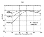
- input power Pin of the optical fiber 12a (namely, output power of the optical transmitter 10), pumping power Pp from the pumping light source 14, and a total length of the optical fibers 12a and 12b, namely a transmission line length L are varied to measure how S/N ratio changes according to length ratio x of the optical fiber 12b to L.
- FIG. 4 shows variations of the S/N ratio relative to x when the fiber input power Pin is varied on condition that the pumping power is 400 mW and the transmission line length L is 300 km.
- the vertical axis shows the S/N ratio
- the horizontal axis shows x.
- FIG. 5 shows deviations from the maximum S/N ratio relative to x.
- the vertical axis shows the deviations from the maximum S/N ratio
- the horizontal axis shows x.
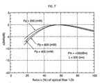
- FIG. 6 shows variations of the S/N ratio relative to x when the Raman pumping power Pp is varied on the condition that the fiber input power Pin is 33 dBm and the transmission line length L is 3000 km.
- the vertical axis shows the S/N ratio
- the horizontal axis shows x.
- FIG. 7 shows deviations from the maximum S/N ratio relative to x. It is clear from FIGS. 6 and 7 that the optimum ratio x of the optical fiber 12b slightly increases according to the Raman pumping power Pp.
- the fiber input power Pin is fixed, it is examined how the ratio of the optical fiber 12b to obtain the maximum S/N ratio varies relative to the Raman pumping power Pp. The result is shown in FIG. 8.
- the vertical axis shows the Raman pumping power Pp, and the horizontal axis shows the ratio x of the optical fiber 12b. It is clear that the optimum ratio x of the optical fiber 12b is proportional to the Raman pumping power Pp, and its slope depends on the transmission line length L.
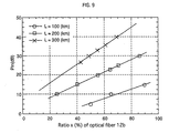
- the Raman pumping power Pp is fixed, it is examined how the optimum ratio of the optical fiber 12b varies relative to the fiber input power Pin. The result is shown in FIG. 9.
- the vertical axis shows the fiber input power Pin (i.e. the output power of the optical transmitter 10), and the horizontal axis shows the ratio x of the optical fiber 12b.
- the optimum ratio x of the optical fiber 12b is proportional to the fiber input power Pin, and its slope depends on the transmission line length L.
- FIG. 10 is obtained from the results shown in FIGS. 8 and 9.
- the fiber input power, the total loss of the optical fibers 12a and 12b, the pumping power for the Raman amplification and the transmission line length are expressed as Pin, ⁇ , Pp and L respectively
- the vertical axis shows (Pin- ⁇ )/(Pp ⁇ 10 Log L)
- the horizontal axis shows the optimum ratio x of the optical fiber 12b.
- y (Pin- ⁇ )/(Pp ⁇ 10 Log L)
- a measured value ⁇ shows a combination of x and y to give the maximum S/N ratio
- measured values ⁇ and ⁇ show a combination of x and y to give S/N ratio 1 dB lower than the maximum S/N ratio.
- y 6.63 ⁇ 10 -2 x-0.077
Landscapes
- Physics & Mathematics (AREA)
- Electromagnetism (AREA)
- Engineering & Computer Science (AREA)
- Computer Networks & Wireless Communication (AREA)
- Signal Processing (AREA)
- Optical Communication System (AREA)
- Optical Modulation, Optical Deflection, Nonlinear Optics, Optical Demodulation, Optical Logic Elements (AREA)
- Lasers (AREA)
- Optical Fibers, Optical Fiber Cores, And Optical Fiber Bundles (AREA)
- Light Guides In General And Applications Therefor (AREA)
Abstract
Description
Claims (4)
- An optical transmission line comprising:a first optical fiber to transmit signal light and have a first effective core area and a first chromatic dispersion value;a second optical fiber to transmit the signal light from the first optical fiber and have a second effective core area smaller than the first effective core area and a second chromatic dispersion value which is either smaller than or to be a negative-polarity of the first chromatic dispersion value;a pumping light source to generate pumping light to cause Raman amplification in the second optical fiber; andan optical coupler to apply the pumping light from the pumping light source into the second optical fiber from the back.
- The optical transmission line of claim 1 wherein on condition that y=(Pin-α)/(Pp ·10 Log L) where input power of the first optical fiber is expressed as Pin (dBm), a total loss of the first and second optical fibers is expressed as α (dB), Raman pumping power is expressed as Pp (dBm), and a total length of the first and second optical fibers is expressed as L (km), y is no more than 6.63×10- 2x+0.123 and no less than 6.63×10⁻²x-0.277 where ratio of the second optical fiber relative to L is expressed as x.
- The optical transmission line of claim 2 wherein y is practically equal to 6.63×10⁻²x-0.077.
- The optical transmission line of any one of claims 1 through 3 wherein an effective core area of the second optical fiber is from 55 µm2 to 70 µm2.
Applications Claiming Priority (2)
| Application Number | Priority Date | Filing Date | Title |
|---|---|---|---|
| JP2000048671 | 2000-02-25 | ||
| JP2000048671A JP2001237777A (en) | 2000-02-25 | 2000-02-25 | Optical transmission path |
Publications (2)
| Publication Number | Publication Date |
|---|---|
| EP1130824A2 true EP1130824A2 (en) | 2001-09-05 |
| EP1130824A3 EP1130824A3 (en) | 2004-09-29 |
Family
ID=18570723
Family Applications (1)
| Application Number | Title | Priority Date | Filing Date |
|---|---|---|---|
| EP01103368A Withdrawn EP1130824A3 (en) | 2000-02-25 | 2001-02-13 | Optical transmission line with Raman amplification |
Country Status (3)
| Country | Link |
|---|---|
| US (1) | US6748178B2 (en) |
| EP (1) | EP1130824A3 (en) |
| JP (1) | JP2001237777A (en) |
Cited By (4)
| Publication number | Priority date | Publication date | Assignee | Title |
|---|---|---|---|---|
| EP1345343A3 (en) * | 2002-03-16 | 2005-04-06 | FITEL USA CORPORATION (a Delaware Corporation) | Raman amplified dispersion compensating modules |
| US6943935B2 (en) | 2001-03-16 | 2005-09-13 | Corning Incorporated | Dispersion-managed cable for raman-assisted transmission |
| US7181118B2 (en) | 2002-07-31 | 2007-02-20 | Corning Incorporated | Non-zero dispersion shifted optical fiber having large effective area, low slope and low zero dispersion |
| WO2010025151A1 (en) | 2008-08-29 | 2010-03-04 | Xtera Communications, Inc. | Remote larger effective area optical fiber |
Families Citing this family (16)
| Publication number | Priority date | Publication date | Assignee | Title |
|---|---|---|---|---|
| JP2001223420A (en) * | 2000-02-10 | 2001-08-17 | Sumitomo Electric Ind Ltd | Raman amplifier, optical transmission system and optical fiber |
| JP4576716B2 (en) * | 2001-01-05 | 2010-11-10 | 住友電気工業株式会社 | Raman gain coefficient measurement method |
| JP2003156649A (en) * | 2001-11-19 | 2003-05-30 | Furukawa Electric Co Ltd:The | Optical fiber |
| EP1326354A3 (en) | 2001-12-07 | 2005-07-20 | Sumitomo Electric Industries, Ltd. | Optical fiber transmission line, optical cable, and optical transmission system |
| US6687443B2 (en) | 2001-12-07 | 2004-02-03 | Sumitomo Electric Industries, Ltd. | Optical fiber transmission line, optical cable, and optical transmission system |
| KR20040075982A (en) | 2002-02-15 | 2004-08-30 | 코닝 인코포레이티드 | Low slope dispersion shifted optical fiber |
| JP3873779B2 (en) | 2002-03-04 | 2007-01-24 | 富士通株式会社 | Raman amplification optical communication system |
| JP2004086143A (en) * | 2002-06-28 | 2004-03-18 | Sumitomo Electric Ind Ltd | Optical transmission system |
| US7102812B2 (en) * | 2002-10-15 | 2006-09-05 | Corning Incorporated | Devices and methods for raman amplification and dispersion compensation |
| US20040252994A1 (en) * | 2003-06-11 | 2004-12-16 | Bickham Scott R. | Optical communication system with suppressed SBS |
| US7558480B2 (en) * | 2003-07-31 | 2009-07-07 | Corning Incorporated | Unrepeatered optical communication system with suppressed SBS |
| JP2006186013A (en) * | 2004-12-27 | 2006-07-13 | Fujitsu Ltd | Optical amplification apparatus and optical amplification method |
| US7336869B2 (en) * | 2006-04-14 | 2008-02-26 | Xtera Communications, Inc. | System and method for implementing a high capacity unrepeatered optical communication system |
| US20080016157A1 (en) * | 2006-06-29 | 2008-01-17 | Centraltouch Technology Inc. | Method and system for controlling and monitoring an apparatus from a remote computer using session initiation protocol (sip) |
| US20120294619A1 (en) * | 2011-05-19 | 2012-11-22 | Tyco Electronics Subsea Communications Llc | Novel architecture for undersea repeaterless systems |
| WO2017196317A1 (en) * | 2016-05-11 | 2017-11-16 | Halliburton Energy Services, Inc. | Providing high power optical pulses over long distances |
Family Cites Families (9)
| Publication number | Priority date | Publication date | Assignee | Title |
|---|---|---|---|---|
| US5191631A (en) * | 1991-12-19 | 1993-03-02 | At&T Bell Laboratories | Hybrid optical fiber and method of increasing the effective area of optical transmission using same |
| FR2685835A1 (en) * | 1991-12-31 | 1993-07-02 | France Telecom | VERY LONG DISTANCE TRANSMISSION SYSTEM ON OPTICAL FIBER COMPENSATED FOR DISTORTIONS AT RECEPTION. |
| US5323404A (en) * | 1993-11-02 | 1994-06-21 | At&T Bell Laboratories | Optical fiber laser or amplifier including high reflectivity gratings |
| JPH09130587A (en) | 1995-10-30 | 1997-05-16 | Canon Inc | Facsimile apparatus and facsimile transmission method |
| JP3418086B2 (en) * | 1997-05-09 | 2003-06-16 | 住友電気工業株式会社 | Optical transmission line for wavelength division multiplexing transmission and method of configuring the same |
| JPH10322283A (en) | 1997-05-21 | 1998-12-04 | Kokusai Denshin Denwa Co Ltd <Kdd> | Optical fiber transmission line |
| US6191854B1 (en) * | 1997-06-23 | 2001-02-20 | Pirelli Cavi E Sistemi S.P.A. | Optical telecommunications system |
| WO1999043107A1 (en) * | 1998-02-20 | 1999-08-26 | Ciena Corporation | Optical amplifier having an improved noise figure |
| MY132931A (en) * | 1998-05-01 | 2007-10-31 | Corning Inc | Dispersion managed optical waveguide and system with distributed amplification |
-
2000
- 2000-02-25 JP JP2000048671A patent/JP2001237777A/en not_active Withdrawn
-
2001
- 2001-02-13 EP EP01103368A patent/EP1130824A3/en not_active Withdrawn
- 2001-02-26 US US09/795,245 patent/US6748178B2/en not_active Expired - Fee Related
Cited By (6)
| Publication number | Priority date | Publication date | Assignee | Title |
|---|---|---|---|---|
| US6943935B2 (en) | 2001-03-16 | 2005-09-13 | Corning Incorporated | Dispersion-managed cable for raman-assisted transmission |
| EP1345343A3 (en) * | 2002-03-16 | 2005-04-06 | FITEL USA CORPORATION (a Delaware Corporation) | Raman amplified dispersion compensating modules |
| CN1306733C (en) * | 2002-03-16 | 2007-03-21 | 菲特尔美国公司 | Dispersion compensation component of Raman amplified |
| US7181118B2 (en) | 2002-07-31 | 2007-02-20 | Corning Incorporated | Non-zero dispersion shifted optical fiber having large effective area, low slope and low zero dispersion |
| WO2010025151A1 (en) | 2008-08-29 | 2010-03-04 | Xtera Communications, Inc. | Remote larger effective area optical fiber |
| EP2321679A4 (en) * | 2008-08-29 | 2015-01-14 | Xtera Communications Inc | REMOVED PART OF OPTICAL FIBER WITH LARGER USEFUL SURFACE |
Also Published As
| Publication number | Publication date |
|---|---|
| EP1130824A3 (en) | 2004-09-29 |
| JP2001237777A (en) | 2001-08-31 |
| US20010021291A1 (en) | 2001-09-13 |
| US6748178B2 (en) | 2004-06-08 |
Similar Documents
| Publication | Publication Date | Title |
|---|---|---|
| US6748178B2 (en) | Optical transmission line | |
| EP1168530B1 (en) | Raman amplifier | |
| US7440167B2 (en) | Optical fiber for Raman amplification, optical fiber coil, Raman amplifier, and optical communication system | |
| US8068275B2 (en) | Method for measuring nonlinear optical properties | |
| US6697558B2 (en) | Raman amplified optical system with reduction of four-wave mixing effects | |
| US7558480B2 (en) | Unrepeatered optical communication system with suppressed SBS | |
| EP1087549A1 (en) | Wdm optical communication system | |
| US6483633B2 (en) | Raman amplifier | |
| US8620155B2 (en) | Optical signal to noise monitor | |
| US8380031B2 (en) | Low nonlinearity long haul optical transmission system | |
| EP1361463A1 (en) | Raman fiber optic amplifier with reduced dispersion | |
| CN100334472C (en) | Wideband optical fibre | |
| US8538218B2 (en) | Unrepeatered long haul optical fiber transmission systems | |
| US7046885B2 (en) | Optical fiber, Raman amplifier, and optical communication system | |
| US7190868B2 (en) | Optical transmission line | |
| US7289710B2 (en) | Optical fiber suitable for high-speed large-scale wdm system, optical transmission line and optical transmission system using the same | |
| JP2002299738A (en) | Optical transmission system | |
| JP3871892B2 (en) | Raman amplification optical system with reduced four-wave mixing effect | |
| JP2005234192A (en) | Dispersion compensating fiber and Raman amplification transmission system | |
| Chi et al. | Comparison of different configurations of distributed Raman amplifiers with dispersion compensation module | |
| JPH08204634A (en) | Repeaterless optical transmission system |
Legal Events
| Date | Code | Title | Description |
|---|---|---|---|
| PUAI | Public reference made under article 153(3) epc to a published international application that has entered the european phase |
Free format text: ORIGINAL CODE: 0009012 |
|
| AK | Designated contracting states |
Kind code of ref document: A2 Designated state(s): AT BE CH CY DE DK ES FI FR GB GR IE IT LI LU MC NL PT SE TR |
|
| AX | Request for extension of the european patent |
Free format text: AL;LT;LV;MK;RO;SI |
|
| 17P | Request for examination filed |
Effective date: 20031104 |
|
| PUAL | Search report despatched |
Free format text: ORIGINAL CODE: 0009013 |
|
| AK | Designated contracting states |
Kind code of ref document: A3 Designated state(s): AT BE CH CY DE DK ES FI FR GB GR IE IT LI LU MC NL PT SE TR |
|
| AX | Request for extension of the european patent |
Extension state: AL LT LV MK RO SI |
|
| RIC1 | Information provided on ipc code assigned before grant |
Ipc: 7H 04B 10/18 B Ipc: 7H 04B 10/17 A |
|
| STAA | Information on the status of an ep patent application or granted ep patent |
Free format text: STATUS: THE APPLICATION HAS BEEN WITHDRAWN |
|
| 18W | Application withdrawn |
Effective date: 20041027 |