EP1130737A1 - Installation électrique autonome, notamment pour véhicule automobile - Google Patents
Installation électrique autonome, notamment pour véhicule automobile Download PDFInfo
- Publication number
- EP1130737A1 EP1130737A1 EP01400551A EP01400551A EP1130737A1 EP 1130737 A1 EP1130737 A1 EP 1130737A1 EP 01400551 A EP01400551 A EP 01400551A EP 01400551 A EP01400551 A EP 01400551A EP 1130737 A1 EP1130737 A1 EP 1130737A1
- Authority
- EP
- European Patent Office
- Prior art keywords
- voltage
- energy storage
- converter
- high voltage
- network
- Prior art date
- Legal status (The legal status is an assumption and is not a legal conclusion. Google has not performed a legal analysis and makes no representation as to the accuracy of the status listed.)
- Granted
Links
Images

Classifications
-
- H—ELECTRICITY
- H02—GENERATION; CONVERSION OR DISTRIBUTION OF ELECTRIC POWER
- H02J—ELECTRIC POWER NETWORKS; CIRCUIT ARRANGEMENTS OR SYSTEMS FOR SUPPLYING OR DISTRIBUTING ELECTRIC POWER; SYSTEMS FOR STORING ELECTRIC ENERGY
- H02J7/00—Circuit arrangements for charging or discharging batteries or for supplying loads from batteries
- H02J7/14—Circuit arrangements for charging or discharging batteries or for supplying loads from batteries for charging batteries from dynamo-electric generators driven at varying speed, e.g. on vehicle
- H02J7/1423—Circuit arrangements for charging or discharging batteries or for supplying loads from batteries for charging batteries from dynamo-electric generators driven at varying speed, e.g. on vehicle with multiple batteries
-
- Y—GENERAL TAGGING OF NEW TECHNOLOGICAL DEVELOPMENTS; GENERAL TAGGING OF CROSS-SECTIONAL TECHNOLOGIES SPANNING OVER SEVERAL SECTIONS OF THE IPC; TECHNICAL SUBJECTS COVERED BY FORMER USPC CROSS-REFERENCE ART COLLECTIONS [XRACs] AND DIGESTS
- Y02—TECHNOLOGIES OR APPLICATIONS FOR MITIGATION OR ADAPTATION AGAINST CLIMATE CHANGE
- Y02T—CLIMATE CHANGE MITIGATION TECHNOLOGIES RELATED TO TRANSPORTATION
- Y02T10/00—Road transport of goods or passengers
- Y02T10/60—Other road transportation technologies with climate change mitigation effect
- Y02T10/70—Energy storage systems for electromobility, e.g. batteries
Definitions
- the present invention relates to an installation supply of at least two electrical networks on which are connected to working consumers respectively under at least two DC voltages different.
- US 5,155,374 provides two sources of voltage, in this case 12 Volts each, which can selectively be connected in series or in parallel.
- the sources are a battery and a supercapacitor.
- the feeder is basically designed to provide the vehicle engine starter with power required without overloading the battery.
- a set of power relays connects the two voltage sources in series to supply the starter in this case at 24 Volts, i.e. the sum tensions from both sources.
- the two sources are then connected in parallel and the supercapacitor can be charged again. So this installation is expected to increase the life of the battery and of course reduces the cross section of the wires from the starter supply network.
- the voltage across the starter does not will be doubled only a very short time after the start from start up. Then it will drop very quickly no only by the ohmic loss in the supercapacitor, but also due to the rapid discharge of this last, to reach the voltage value of the drums. This will therefore bear the entire burden of starter well before the engine actually started. It is even to be feared that the supercapacitor will charge upside down if no precautions are taken.
- the alternator of a motor vehicle electrical installation is sized and piloted during its operation so that, when the internal combustion engine is running, it can provide the necessary average energy and power to handle all requests from the vehicle network automobile.
- the energy storage system must assume two roles to know on the one hand that of "power supplier” which consists in satisfying the sudden demands for power for example ensuring the start up and form a buffer in case of other requests for sudden and significant power, and that on the other hand, of "energy supplier” which consists in maintaining on a more or less prolonged period certain functions electric for example during punctual stops (function automatic restart also called “stop-and-go”) or extended when the vehicle is not in use.
- This known installation includes a high section voltage S1 under 36/42 Volts for example and a section low voltage S2 at 12/14 Volts for example. These two sections are separated by a DC-DC converter reversible C, capable of transforming high voltage into low voltage and vice versa.
- section S1 alternator A and the starter D as well as other CS1 consumers asking relatively strong powers.
- Distribution rail R1 of this section is under 36/42 Volts and a SC supercapacitor is connected to it.
- consumers CS2 are provided of relatively low power and working under 12/14 Volts. They are connected to an R2 rail brought to this voltage and connected to a battery B.
- the whole is controlled by a CP computer.
- the SC supercapacitor allows the vehicle to be started by first supplying power to the starter and filter the power peaks generated by the start-up of certain large consumers to avoid voltage drops on the network.
- Battery B on its side can be dimensioned at more just to meet energy demands and also for an optimal lifetime by reducing as much as possible its depth of discharge.
- a supercapacitor also has a "base” voltage U fls (called “floating voltage”) which is the voltage at which it can be maintained permanently without degradation.
- the supercapacitor can withstand voltages greater than the base voltage U fls provided that the duration of application of the voltage is limited. Thus, a duration of application of one second of the voltage U max can generally be allowed.
- supercapacitors are commercially available in the form of elements which generally have a base voltage of the order of 3.2 volts so that in order to be able to use them in the installation of FIG. 1, there a plurality of these elements must be connected in series.
- the base voltages U fl of the supercapacitor elements are not identical so that, when placed in series, the total base voltage U fls of the assembly will be less than the corresponding multiple of the voltages basic nominal unit values of the elements with a factor of uncertainty all the more important as the number of elements to be used is important.
- the problem which is to the basis of the invention thus consists in making optimal the use of supercapacitors in an installation power supply at several voltages, especially for motor vehicle.
- FIG. 1 The supply installation of FIG. 1, known from the prior art and briefly described above, can be carried out according to a variant in which the supercapacitor is replaced by a battery accumulators which in fact performs the same functions and is connected in the same way.
- this battery must have the number of cells necessary to supply the required high voltage.
- P / E power / energy ratio which determines the mass and volume energy and the price.
- the mass energy decreases and the price increases exponentially with increasing P / E ratio.
- the problem at hand basis of the invention thus consists in proposing a better compromise on the use of batteries as sources of power in a power installation at several voltages, especially for motor vehicles.
- the invention aims to solve the stated problem above in two ways.
- the energy storage can be dimensioned so optimal.
- the storage device connected to the low voltage network is a battery and in that the storage device connected to the high voltage network is a supercapacitor.
- the voltage of the supercapacitor complements that of the battery up to the voltage of the high-voltage network, it becomes possible to reduce the elements of the supercapacitor and so simplify the structure and to facilitate the mounting of this supercapacitor.
- said electrical energy storage devices are batteries.
- This feature also reduces the size of the second energy storage device, the total tension should also only complement that provided by the first energy storage device, until forming with the latter the tension under which must operate the high voltage network.
- said batteries form a unitary assembly, whereby the size of the batteries is minimal, their characteristics can be chosen according to the importance of consumers connected respectively to the high and low networks voltage, and their lifespan can be maximum.
- the invention also relates to a vehicle automobile equipped with an internal combustion engine and a starter mechanically coupled to the latter, characterized in what it includes an electrical installation presenting one or more of the characteristics as defined above.
- the starter can be a consumer either high voltage network, or the low voltage network.
- the starter is, in a manner known per se, made in the form of a combined machine also comprising said electricity producing machine it is possible according to another characteristic of the invention, that said combined machine is connected in said high network voltage.
- Figure 2 represents a first embodiment of the invention.
- the installation is intended to ensure power supply to a motor vehicle but specialists will readily understand that others applications of this installation are possible in the extent that such an application requires the provision electrical energy to loads some of which operate under a relatively low first voltage and others under a relatively high second voltage.
- the networks to which the consumers or loads are connected are represented by blocks 1 and 2, the network 1 operating at a relatively low voltage of 12/14 Volts for example, and the network 2 at a relatively high voltage.
- 36/42 Volts for example, these values are obviously not limiting, although they are generally accepted in automotive technology and are therefore well suited in this application. It will be noted that the values 12 and 36 Volts represent the voltage One of the energy storage devices used and that the values 14 and 42 Volts represent the voltage U max .
- the power plant includes a first electrical storage device 3 at the terminals which network 1 is connected to.
- This first device energy storage is also connected between a terminal common 4a and a low voltage terminal 4b of a reversible 4 continuous / continuous converter.
- the power plant according to the invention also includes a second storage device 5 of electrical energy which is connected in series with the first energy storage device 3 and the terminal opposite the latter is connected to network 2 at high voltage and to the high voltage terminal 4c of the converter 4.
- the two networks 1 and 2 have a common terminal 6 which is preferably the mass of the installation.
- the supply system also includes a device 7 generator of electrical energy.
- this generator device 7 can be a single machine electric selectively acting as an alternator (associated with a rectifier) and starter.
- alternator 8 also associated with a rectifier
- a starter 9 is provided also separate then forming part of the charges of the electrical network 2.
- the installation finally includes a computer symbolized by block 10 and designed to manage and steer the whole operation of the installation.
- This computer has a series of inputs 10a and a series 10b functionally connected to various sensors and installation organs to allow the accomplishment of its task. His connections were not designed for the sake of simplification.
- the first electrical energy storage device 3 is a conventional storage battery delivering 12/14 Volts. It is dimensioned so that it can assume its role as a source of energy in the sense explained above.
- the second energy storage device 5 is a supercapacitor whose number of elements supercapacitors in series is chosen so that the whole delivers a voltage of 24/28 Volts i.e. complement to low voltage, allowing reach high voltage. Therefore, compared in the circuit of FIG. 1, this storage device can be made with fewer elements and has less selection problems to fix the tension he delivers.
- FIG. 3 represents as a function of time, by the curve a, the voltage U tot present at the terminals of the series connection of the two energy storage devices 3 and 5, and by the curve b, that U beats present at the terminals of the battery 3.
- the battery 3 and the supercapacitor 5 When the vehicle is abandoned for a relatively long time which can reach several weeks, the battery 3 and the supercapacitor 5 have adopted their "abandon" voltages linked to relaxations, temperature and self-discharge, the voltage U tot having gone down below the total base voltage U flt of the two storage devices.
- the converter 4 then isolates these two devices from each other (phase 1 of the diagram in FIG. 3).
- the computer 10 will be awakened at the first action the driver of the vehicle, for example by acting on the door opening remote control or any other manifestation of the proximity of the remote control by report to the vehicle.
- the computer 10 also having the temperature of the vehicle engine, it calculates using a stored characteristic field, the power required for starting and deduces therefrom the voltage which the supercapacitor must supply during starting. If the voltage Us is lower than the required voltage, (case represented in the diagram), the computer controls the converter 4 so that it ensures the conversion in the direction 12/14 Volts ⁇ 36/42 Volts to charge the supercapacitor with l using the energy drawn from the battery 3, until the voltage U tot reaches the required value.
- this charging of the supercapacitor can be carried out up to the voltage U maxt which is the maximum total voltage which can be admitted at the terminals of the series connection, since the starting which will immediately follow will cause an immediate drop in this voltage thus avoiding damage of the supercapacitor (phase 2 of the diagram).
- a warning light on the vehicle's dashboard can indicate this charging period.
- the computer 4 initiates the start-up procedure by controlling the starter 8 or 9 (phase 3 of the diagram).
- Start-up phase 3 will continue either until the engine starts, until, for reasons for protecting storage devices, one either of the minimum voltages is reached.
- the calculator 4 can also monitor other criteria and suspend the startup process if a such a criterion is not satisfied. It is to highlight that during phase 3, the converter 4 is deactivated.
- the computer 4 activates the alternator 7 or 8 and commands the recharging of the supercapacitor 5 to its own basic voltage U fls .
- the alternator charges the battery 3 at its base voltage U flb , this charging phase (phase 4 of the diagram) ending when the voltage U tot has reached the value of the total base voltage U flt .
- the low voltage network 1 is supplied by the converter 4 and the high voltage network 2 by the alternator 7 or 8 and this configuration will be maintained throughout the operation of the vehicle symbolized by phase 5.
- the computer 10 adjusts the alternator so that it supplies the power necessary for recharging the storage devices and for supplying the consumers of the networks 1 and 2.
- the charging of storage devices 3 and 5 is performed in such a way that they are permanently maintained at their respective base voltages Uflb and Ufls.
- phase 6 it is assumed that the vehicle stopped momentarily for example at a traffic light red. After a predetermined time interval, the computer 10 controls engine stopping.
- the result a reduction in the voltage in the two networks 1 and 2, that of network 1 being the most sensitive, because advantageously, the loads of the high voltage network 2 are shed, since they represent mostly consumers who are not essential for the operation of the vehicle or for maintaining security conditions. In any condition cause it is made so that the voltage reduction on networks be as less noticeable as possible for the occupants of the vehicle. For this it is desirable that any sudden drop in voltage is avoided.
- the computer 10 by examining the temperature of the engine, can determine, for example using a characteristic field in memory, a voltage value below which the engine could not start at the temperature considered.
- the computer 10 controls the load shedding so that the voltage, on the one hand follows a predetermined curve, for example that shown for phase 6 of FIG. 3 ensuring a gradual reduction in the voltage which is not perceptible, and on the other hand part does not go below the voltage value U mintc .
- the computer 10 controls the converter 4 so that it sends energy present on the network 2 towards network 1, so as to also absorb the fall in voltage in network 1, in which, as already specified, the essential consumers are included like the computer itself or the lighthouses for example.
- the vehicle In the next phase 7, the vehicle is still stopped, the installation no longer draws energy on the high voltage network, so that the low voltage storage 3 gradually discharges in supplying consumers connected to the low network voltage 1.
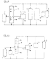
- FIG. 4 represents a variant of the invention in which the two storage devices form a single energy storage unit 11 composed, according to a series connection, of a section of accumulators 11a to low voltage (12/14 Volts for example) and a section llb high voltage batteries (24/28 Volts, per example).
- FIG. 4A which represents the same arrangement as a storage unit than that of FIG. 4, the starter 9 is connected to the low voltage network 1, section 11a will be sized to be able to provide sufficient power to power this starter, section llb can be more lightly dimensioned for, optimally, ability to maintain high voltage on network 2.
- the invention is not limited to the modes of realization described and represented. This is how example that we could consider feeding more than two networks each having a different natural voltage and associated with a dimensioned energy storage device optimally for energy or power level to provide instantly or continuously to their network corresponding.
Landscapes
- Engineering & Computer Science (AREA)
- Power Engineering (AREA)
- Charge And Discharge Circuits For Batteries Or The Like (AREA)
Abstract
Description
- au moins deux réseaux électriques qui sont alimentés respectivement sous au moins une basse tension continue et au moins une haute tension continue et auxquels sont raccordés des consommateurs électriques;
- au moins des premier et deuxième dispositifs de stockage d'énergie électrique raccordés respectivement auxdits réseaux;
- au moins une machine productrice d'électricité raccordée à l'un desdits réseaux,
- au moins un convertisseur réversible continu/continu connecté auxdits dispositifs de stockage d'énergie électrique et à ladite machine productrice d'électricité et présentant une borne commune, une borne basse tension et une borne haute tension, et
- un calculateur électronique de pilotage dudit
convertisseur et de ladite machine productrice
d'électricité, pour commander sélectivement le sens de
conversion dudit convertisseur en fonction de la
consommation électrique imposée auxdits réseaux par lesdits
consommateurs, pour déterminer l'état de charge de chacun
desdits dispositifs de stockage d'énergie électrique en
utilisant, selon le cas, l'énergie électrique fournie par
ladite machine productrice d'électricité et/ou au moins
l'un desdits dispositifs de stockage d'énergie électrique,
caractérisée en ce que - lesdits dispositifs de stockage d'énergie électrique sont connectés selon un montage en série dont le point intermédiaire est raccordé à ladite borne commune dudit convertisseur et à un côté du réseau basse tension, dont une première extrémité est connectée en commun auxdits réseaux et à ladite borne basse tension du convertisseur et dont une seconde extrémité est connectée au réseau haute tension et ladite borne haute tension du convertisseur.
- à fixer des premier et second niveaux de tensions admissibles respectivement maximale et minimale sur ledit réseau haute tension et un troisième niveau de tension admissible minimale sur ledit réseau basse tension;
- à commander ledit convertisseur pour précharger ledit second dispositif de stockage d'énergie à partir dudit premier dispositif de stockage d'énergie jusqu'à ce que la tension dudit réseau haute tension atteigne au moins une valeur suffisante pour le démarrage;
- à déclencher ledit démarreur;
- et, pendant le fonctionnement du démarreur, à maintenir la tension dudit réseau haute tension à une valeur au moins égale audit second niveau de tension, en complétant au besoin la charge dudit second dispositif de stockage d'énergie à partir dudit premier dispositif de stockage d'énergie par l'intermédiaire dudit convertisseur;
- et à interrompre le démarrage, le cas échéant, si la tension sur ledit réseau basse tension diminue jusqu'audit troisième niveau de tension.
- ladite opération de précharge consiste à charger ledit second dispositif de stockage d'énergie jusqu'à la valeur de tension maximale admissible à laquelle peut être soumis ledit second dispositif de stockage d'énergie;
- en régime de fonctionnement dudit moteur à combustion interne, les tensions sur lesdites réseaux basse et haute tension sont régulées aux valeurs respectives de base desdits dispositifs de stockage d'énergie;
- dans le cas où le véhicule est équipé d'un
système de redémarrage automatique, il consiste:
- à fixer une valeur à respecter pour la tension minimale dudit réseau haute tension en fonction de la température de fonctionnement dudit moteur à combustion interne, et
- à l'arrêt provisoire du véhicule, moteur stoppé, à réduire progressivement la tension dudit réseau haute tension jusqu'à ce que ladite valeur à respecter de tension soit atteinte, par transfert d'énergie dudit premier dispositif de stockage vers le second par l'intermédiaire dudit convertisseur.
- la figure 1 déjà décrite est un schéma d'une installation d'alimentation bi-tension selon la technique antérieure;
- la figure 2 est un schéma d'un premier mode de réalisation d'une installation d'alimentation selon l'invention;
- la figure 3 est un diagramme des temps illustrant le fonctionnement de l'installation d'alimentation selon l'invention; et
- les figures 4 et 4A illustrent deux variantes d'un second mode de réalisation selon l'invention.
- la tension et la température du dispositif 3 de stockage basse tension de l'installation;
- la tension et la température du dispositif 5 de stockage haute tension;
- la température du moteur à combustion interne (non représenté) du véhicule;
- l'état du démarreur 9 et de l'alternateur 8 ou de la machine 7 faisant office à la fois de démarreur et d'alternateur;
- l'état du convertisseur 4;
- l'état de la clé de contact (non représentée);
- l'intensité des courants traversant respectivement les dispositifs de stockage 3 et 5;
- l'état de charge des deux dispositifs de stockage 3 et 5.
- la tension et la puissance de sortie de l'alternateur 8 ou de la machine combinée 7;
- la mise en marche du démarreur 9 ou de la machine combinée 7;
- le sens de fonctionnement du convertisseur 4;
- les puissances de sortie dans les deux sens du convertisseur 4;
- l'allumage d'un voyant sur le tableau de bord du véhicule (non représenté).
Claims (12)
- Installation électrique autonome comprenant :caractérisée en ce queau moins deux réseaux électriques (1, 2) qui sont alimentés respectivement sous au moins une basse tension continue et au moins une haute tension continue et auxquels sont raccordés des consommateurs électriques;au moins des premier et deuxième dispositifs de stockage d'énergie électrique (3, 5; 11a, 11b) raccordés respectivement auxdits réseaux (1, 2);au moins une machine productrice d'électricité (7; 8) raccordée à l'un desdits réseaux (2),au moins un convertisseur réversible continu/continu (4) connecté auxdits dispositifs de stockage d'énergie électrique (3, 5; 11a, llb) et à ladite machine productrice d'électricité (7; 8) et présentant une borne commune (4a), une borne basse tension (4b) et une borne haute tension (4c), etun calculateur électronique (10) de pilotage dudit convertisseur (4) et de ladite machine productrice d'électricité (7; 8), pour commander sélectivement le sens de conversion dudit convertisseur (4) en fonction de la consommation électrique imposée auxdits réseaux (1, 2) par lesdits consommateurs, pour déterminer l'état de charge de chacun desdits dispositifs de stockage d'énergie électrique (3, 5; 11a, 11b) en utilisant, selon le cas, l'énergie électrique fournie par ladite machine productrice d'électricité (7; 8) et/ou au moins l'un desdits dispositifs de stockage d'énergie électrique (3, 5; 11a, 11b),lesdits dispositifs de stockage d'énergie électrique (3, 5; 11a, 11b) sont connectés selon un montage en série dont le point intermédiaire est raccordé à ladite borne commune (4a) dudit convertisseur (4) et à un côté du réseau basse tension et dont une première extrémité (6) est connectée en commun auxdits réseaux (1, 2) et à ladite borne basse tension (4b) du convertisseur (4) et dont une seconde extrémité est connectée au réseau haute tension (2) et à ladite borne haute tension (4c) du convertisseur (4).
- Installation électrique autonome suivant la revendication 1, caractérisée en ce que le dispositif de stockage (4) raccordé au réseau basse tension (1) est une batterie et en ce que le dispositif de stockage (5) raccordé au réseau haute tension (2) est un supercondensateur.
- Installation électrique autonome suivant la revendication 1, caractérisée en ce que lesdits dispositifs de stockage d'énergie électrique (11) sont des batteries (11a, 11b).
- Installation électrique autonome suivant la revendication 3, caractérisée en ce que lesdites batteries (11a, 11b) forment un ensemble unitaire (11).
- Véhicule automobile équipé d'un moteur à combustion interne et d'un démarreur (7; 9) couplé mécaniquement à ce dernier, caractérisé en ce qu'il comprend une installation électrique selon l'une quelconque des revendications 1 à 4.
- Véhicule automobile suivant la revendication 5, caractérisé en ce que le démarreur (9) est un consommateur du réseau haute tension (2).
- Véhicule automobile suivant la revendication 5, caractérisé en ce que le démarreur (9) est un consommateur du réseau basse tension (1).
- Véhicule automobile suivant la revendication 5, caractérisé en ce que le démarreur étant réalisé sous la forme d'une machine combinée (7) comprenant également ladite machine productrice d'électricité, ladite machine combinée (7) est connectée dans ledit réseau haute tension (2).
- Procédé pour la mise en oeuvre d'une installation électrique autonome dans un véhicule suivant l'une quelconque des revendications 5 et 6, caractérisé en ce qu'il consiste, lors du démarrage à froid dudit moteur à combustion interne,à fixer des premier et second niveaux de tensions admissibles respectivement maximale (Umaxt) et minimale (Umintf) sur ledit réseau haute tension (2) et un troisième niveau de tension (Uminb) admissible minimale sur ledit réseau basse tension (2);à commander ledit convertisseur (4) pour précharger ledit second dispositif de stockage d'énergie (5; 11b) à partir dudit premier dispositif de stockage d'énergie (3; 11a) jusqu'à ce que la tension dudit réseau haute tension (2) atteigne au moins une valeur suffisante pour le démarrage;à déclencher ledit démarreur (8; 9);et, pendant le fonctionnement du démarreur (8; 9), à maintenir la tension dudit réseau haute tension à une valeur au moins égale audit second niveau de tension (Umintf), en complétant au besoin la charge dudit second dispositif de stockage d'énergie (5;11b) à partir dudit premier dispositif de stockage d'énergie (3; 11a) par l'intermédiaire dudit convertisseur (4);et à interrompre le démarrage, le cas échéant, si la tension sur ledit réseau basse tension (2) atteigne ledit troisième niveau de tension (Uminb).
- Procédé suivant la revendication 9, caractérisé en ce que ladite opération de précharge consiste à charger ledit second dispositif de stockage d'énergie (5; 11b) jusqu'à la valeur de tension maximale admissible (Umaxt) à laquelle peut être soumis ledit second dispositif de stockage d'énergie (5; 11b).
- Procédé suivant l'une quelconque des revendications 9 et 10, caractérisé en ce qu'en régime de fonctionnement dudit moteur à combustion interne les tensions sur lesdites réseaux basse et haute tension (1, 2) sont régulées aux valeurs respectives de base (Uflb, Ufls) desdits dispositifs de stockage d'énergie.
- Procédé suivant l'une quelconque des revendications 9 à 11, caractérisé en ce que, dans le cas où le véhicule est équipé d'un système de redémarrage automatique, il consiste,à fixer une valeur (Umintc) à respecter pour la tension minimale dudit réseau haute tension (2) en fonction de la température de fonctionnement dudit moteur à combustion interne, età l'arrêt provisoire du véhicule, moteur stoppé, à réduire progressivement la tension dudit réseau haute tension (2) jusqu'à ce que ladite valeur à respecter de tension (Umintc) soit atteinte, par transfert d'énergie dudit premier dispositif de stockage (3; 11a) vers le second (5; llb) par l'intermédiaire dudit convertisseur (4).
Applications Claiming Priority (2)
| Application Number | Priority Date | Filing Date | Title |
|---|---|---|---|
| FR0002770A FR2805935B1 (fr) | 2000-03-03 | 2000-03-03 | Installation electrique autonome, notamment pour vehicule automobile |
| FR0002770 | 2000-03-03 |
Publications (2)
| Publication Number | Publication Date |
|---|---|
| EP1130737A1 true EP1130737A1 (fr) | 2001-09-05 |
| EP1130737B1 EP1130737B1 (fr) | 2009-09-02 |
Family
ID=8847701
Family Applications (1)
| Application Number | Title | Priority Date | Filing Date |
|---|---|---|---|
| EP01400551A Expired - Lifetime EP1130737B1 (fr) | 2000-03-03 | 2001-03-02 | Installation électrique autonome, notamment pour véhicule automobile |
Country Status (3)
| Country | Link |
|---|---|
| EP (1) | EP1130737B1 (fr) |
| DE (1) | DE60139739D1 (fr) |
| FR (1) | FR2805935B1 (fr) |
Cited By (14)
| Publication number | Priority date | Publication date | Assignee | Title |
|---|---|---|---|---|
| FR2838572A1 (fr) * | 2002-04-12 | 2003-10-17 | Valeo Equip Electr Moteur | Systeme de charge d'un dispositif de stockage d'energie electrique, tel qu'un super-condensateur a partir d'une batterie et notamment d'un vehicule automobile, et procede d'utilisation de ce systeme |
| WO2004017152A1 (fr) * | 2002-07-17 | 2004-02-26 | Siemens Aktiengesellschaft | Circuiterie pour stabiliser une tension d'alimentation et procede pour faire fonctionner cette circuiterie |
| FR2848736A1 (fr) * | 2002-12-17 | 2004-06-18 | Peugeot Citroen Automobiles Sa | Systeme d'alimentation electrique d'au moins une charge |
| FR2888058A1 (fr) * | 2005-07-04 | 2007-01-05 | Peugeot Citroen Automobiles Sa | Installation electrique de bord pour vehicule automobile |
| FR2910191A1 (fr) * | 2006-12-15 | 2008-06-20 | Valeo Equip Electr Moteur | Dispositif de pre-charge de moyens de stockage d'energie associes a une machine electrique tournante |
| FR2937424A1 (fr) * | 2008-10-21 | 2010-04-23 | Valeo Equip Electr Moteur | Procede et dispositif de detection de la fin de vie d'un pack de supercondensateur dans un systeme electrique de vehicule automobile |
| WO2010130527A1 (fr) * | 2009-05-12 | 2010-11-18 | Continental Automotive Gmbh | Circuit de stabilisation de la tension de réseau |
| WO2011012428A3 (fr) * | 2009-07-31 | 2011-06-30 | Robert Bosch Gmbh | Circuit pour un réseau de bord |
| WO2011121035A1 (fr) * | 2010-03-30 | 2011-10-06 | Continental Automotive Gmbh | Réseau de bord pour un véhicule ainsi que dispositif de commande pour un réseau de bord |
| CN101161498B (zh) * | 2006-10-11 | 2012-05-23 | 现代自动车株式会社 | 混合燃料电池客车的电力系统及其控制方法 |
| WO2013189643A1 (fr) * | 2012-06-22 | 2013-12-27 | Robert Bosch Gmbh | Procédé et dispositif pour démarrer un véhicule à moteur |
| DE102015208542A1 (de) * | 2015-05-07 | 2016-09-08 | Continental Automotive Gmbh | Versorgungseinrichtung für ein Bordnetz und Bordnetz mit Versorgungseinrichtung |
| EP3276774A1 (fr) * | 2016-07-29 | 2018-01-31 | Airbus Helicopters | Architecture electrique a double reseau electrique secondaire pour le demarrage des moteurs d'un aeronef |
| RU2684971C1 (ru) * | 2017-12-13 | 2019-04-16 | Эйрбас Хеликоптерс | Электрическая система с двойной вторичной электросетью для запуска двигателей летательных аппаратов |
Families Citing this family (2)
| Publication number | Priority date | Publication date | Assignee | Title |
|---|---|---|---|---|
| DE102009049321A1 (de) | 2009-10-14 | 2011-04-21 | Bayerische Motoren Werke Aktiengesellschaft | Energiespeicher-System zur elektrischen Energieversorgung von Verbrauchern in einem Fahrzeug |
| DE102011006518A1 (de) * | 2011-03-31 | 2012-10-04 | Robert Bosch Gmbh | Spannungsversorgungseinheit |
Citations (3)
| Publication number | Priority date | Publication date | Assignee | Title |
|---|---|---|---|---|
| DE4226311A1 (de) * | 1992-08-08 | 1994-02-10 | Audi Ag | Drehstromgenerator |
| DE19724356C1 (de) * | 1997-06-10 | 1998-05-07 | Daimler Benz Ag | Energieversorgungsschaltung für ein Kraftfahrzeugbordnetz mit drei Spannungsebenen |
| DE19838973A1 (de) * | 1998-08-27 | 2000-03-02 | Bosch Gmbh Robert | Mehrspannungsbordnetz für ein Fahrzeug |
Family Cites Families (2)
| Publication number | Priority date | Publication date | Assignee | Title |
|---|---|---|---|---|
| DE19755050C2 (de) * | 1997-12-11 | 2001-10-18 | Bosch Gmbh Robert | Einrichtung zur Energieversorgung in einem Kraftfahrzeugbordnetz |
| DE19846319C1 (de) * | 1998-10-08 | 2000-02-17 | Daimler Chrysler Ag | Energieversorgungsschaltung für ein Kraftfahrzeugbordnetz mit zwei Spannungsversorgungszweigen |
-
2000
- 2000-03-03 FR FR0002770A patent/FR2805935B1/fr not_active Expired - Fee Related
-
2001
- 2001-03-02 DE DE60139739T patent/DE60139739D1/de not_active Expired - Lifetime
- 2001-03-02 EP EP01400551A patent/EP1130737B1/fr not_active Expired - Lifetime
Patent Citations (3)
| Publication number | Priority date | Publication date | Assignee | Title |
|---|---|---|---|---|
| DE4226311A1 (de) * | 1992-08-08 | 1994-02-10 | Audi Ag | Drehstromgenerator |
| DE19724356C1 (de) * | 1997-06-10 | 1998-05-07 | Daimler Benz Ag | Energieversorgungsschaltung für ein Kraftfahrzeugbordnetz mit drei Spannungsebenen |
| DE19838973A1 (de) * | 1998-08-27 | 2000-03-02 | Bosch Gmbh Robert | Mehrspannungsbordnetz für ein Fahrzeug |
Cited By (27)
| Publication number | Priority date | Publication date | Assignee | Title |
|---|---|---|---|---|
| FR2838572A1 (fr) * | 2002-04-12 | 2003-10-17 | Valeo Equip Electr Moteur | Systeme de charge d'un dispositif de stockage d'energie electrique, tel qu'un super-condensateur a partir d'une batterie et notamment d'un vehicule automobile, et procede d'utilisation de ce systeme |
| WO2004017152A1 (fr) * | 2002-07-17 | 2004-02-26 | Siemens Aktiengesellschaft | Circuiterie pour stabiliser une tension d'alimentation et procede pour faire fonctionner cette circuiterie |
| US7230351B2 (en) | 2002-07-17 | 2007-06-12 | Siemens Aktiengesellschaft | Circuit arrangement for stabilizing a supply voltage and method for operating said circuit arrangement |
| DE10232416B4 (de) * | 2002-07-17 | 2007-11-22 | Siemens Ag | Schaltungsanordnung und Verfahren zum Stabilisieren einer Versorgungsspannung |
| FR2848736A1 (fr) * | 2002-12-17 | 2004-06-18 | Peugeot Citroen Automobiles Sa | Systeme d'alimentation electrique d'au moins une charge |
| FR2888058A1 (fr) * | 2005-07-04 | 2007-01-05 | Peugeot Citroen Automobiles Sa | Installation electrique de bord pour vehicule automobile |
| CN101161498B (zh) * | 2006-10-11 | 2012-05-23 | 现代自动车株式会社 | 混合燃料电池客车的电力系统及其控制方法 |
| FR2910191A1 (fr) * | 2006-12-15 | 2008-06-20 | Valeo Equip Electr Moteur | Dispositif de pre-charge de moyens de stockage d'energie associes a une machine electrique tournante |
| WO2008074951A1 (fr) * | 2006-12-15 | 2008-06-26 | Valeo Equipements Electriques Moteur | Dispositif de pre-charge de moyens de stockage d'energie associes a une machne electrique tournante |
| FR2937424A1 (fr) * | 2008-10-21 | 2010-04-23 | Valeo Equip Electr Moteur | Procede et dispositif de detection de la fin de vie d'un pack de supercondensateur dans un systeme electrique de vehicule automobile |
| WO2010046576A3 (fr) * | 2008-10-21 | 2010-06-17 | Valeo Equipements Electriques Moteur | Procede et dispositif de detection de la fin de vie d'un pack de supercondensateur dans un systeme electrique de vehicule automobile |
| WO2010130527A1 (fr) * | 2009-05-12 | 2010-11-18 | Continental Automotive Gmbh | Circuit de stabilisation de la tension de réseau |
| WO2011012428A3 (fr) * | 2009-07-31 | 2011-06-30 | Robert Bosch Gmbh | Circuit pour un réseau de bord |
| US9150170B2 (en) | 2009-07-31 | 2015-10-06 | Robert Bosch Gmbh | Circuit system for redistribution of electrical energy in a vehicle |
| WO2011121035A1 (fr) * | 2010-03-30 | 2011-10-06 | Continental Automotive Gmbh | Réseau de bord pour un véhicule ainsi que dispositif de commande pour un réseau de bord |
| CN102470811B (zh) * | 2010-03-30 | 2015-01-07 | 大陆汽车有限公司 | 车辆的车载电源以及用于车载电源的控制设备 |
| US8933580B2 (en) | 2010-03-30 | 2015-01-13 | Continental Automotive Gmbh | On-board electrical system for a vehicle and also control apparatus for an on-board electrical system |
| CN102470811A (zh) * | 2010-03-30 | 2012-05-23 | 欧陆汽车有限责任公司 | 车辆的车载电源以及用于车载电源的控制设备 |
| WO2013189643A1 (fr) * | 2012-06-22 | 2013-12-27 | Robert Bosch Gmbh | Procédé et dispositif pour démarrer un véhicule à moteur |
| CN104379392A (zh) * | 2012-06-22 | 2015-02-25 | 罗伯特·博世有限公司 | 用于起动机动车的方法和系统 |
| US9873337B2 (en) | 2012-06-22 | 2018-01-23 | Robert Bosch Gmbh | Method and system for starting a motor vehicle |
| DE102015208542A1 (de) * | 2015-05-07 | 2016-09-08 | Continental Automotive Gmbh | Versorgungseinrichtung für ein Bordnetz und Bordnetz mit Versorgungseinrichtung |
| EP3276774A1 (fr) * | 2016-07-29 | 2018-01-31 | Airbus Helicopters | Architecture electrique a double reseau electrique secondaire pour le demarrage des moteurs d'un aeronef |
| US20180029721A1 (en) * | 2016-07-29 | 2018-02-01 | Airbus Helicopters | Electrical architecture with paired secondary electrical networks for starting engines of an aircraft |
| FR3054738A1 (fr) * | 2016-07-29 | 2018-02-02 | Airbus Helicopters | Architecture electrique a double reseau electrique secondaire pour le demarrage des moteurs d'un aeronef |
| US10787273B2 (en) | 2016-07-29 | 2020-09-29 | Airbus Helicopters | Electrical architecture with paired secondary electrical networks for starting engines of an aircraft |
| RU2684971C1 (ru) * | 2017-12-13 | 2019-04-16 | Эйрбас Хеликоптерс | Электрическая система с двойной вторичной электросетью для запуска двигателей летательных аппаратов |
Also Published As
| Publication number | Publication date |
|---|---|
| FR2805935A1 (fr) | 2001-09-07 |
| FR2805935B1 (fr) | 2002-05-10 |
| DE60139739D1 (de) | 2009-10-15 |
| EP1130737B1 (fr) | 2009-09-02 |
Similar Documents
| Publication | Publication Date | Title |
|---|---|---|
| EP1130737B1 (fr) | Installation électrique autonome, notamment pour véhicule automobile | |
| EP2715909B1 (fr) | Procede de rechargement d'un couple de batteries de vehicule de tensions nominales differentes, et systeme associe | |
| EP2032383B1 (fr) | Dispositif micro-hybride pour vehicule automobile | |
| CA2943474C (fr) | Procede et systeme de reactivation rapide de turbomachine | |
| FR2784517A1 (fr) | Circuit d'alimentation en energie pour un reseau de bord de vehicule automobile a deux branches d'alimentation de tensions differentes | |
| EP2904690A2 (fr) | Réseau électrique pour véhicule automobile | |
| FR2988926A1 (fr) | Procede et systeme d'alimentation electrique d'un vehicule automobile hybride a double stockeurs d'energie electrique | |
| WO2020074397A1 (fr) | Procédé et dispositif de régulation du niveau de charge d'une batterie de traction d'un véhicule électrique | |
| WO2001079019A1 (fr) | Circuit d'alimentation electrique a tension multiple pour vehicule automobile | |
| EP2346711A2 (fr) | Procede et dispositif de commande d'un systeme micro-hybride a freinage recuperatif apte a equiper un vehicule automobile | |
| EP1848090A2 (fr) | Dispositif de suralimentation temporaire en puissance d'organes électriques | |
| CA3183945A1 (fr) | Procede de pilotage de charge et de decharge d'une pluralite de dispositifs de stockage d'energie electrique | |
| WO2012131235A2 (fr) | Procede et systeme d'alimentation electrique redondante d'un vehicule automobile hybride | |
| EP1309064A2 (fr) | Procédé de gestion du fonctionnement d'une source de stockage d'énergie électrique, notamment d'un supercondensateur | |
| WO2004054066A1 (fr) | Systeme et procede d'alimentation electrique a deux tensions pour vehicule | |
| FR2928049A1 (fr) | Cellule pour dispositif de stockage d'energie electrique et systeme d'alimentation electrique du reseau de bord d'un vehicule. | |
| FR2913825A1 (fr) | Procede et dispositif de recharge d'un stockage d'energie electrique d'un vehicule. | |
| WO2022018226A1 (fr) | Systeme d'alimentation d'un moteur de traction | |
| FR3039934A1 (fr) | Procede de gestion de l’alimentation electrique d’un vehicule automobile | |
| EP2965398B1 (fr) | Dispositif d'alimentation commute pour le réseau de bord d'un véhicule automobile | |
| EP1642764B1 (fr) | Système de contrôle du fonctionnement de moyens de stockage d'énergie électrique de moyens de motorisation hybride | |
| FR3059956B1 (fr) | Demarrage du moteur thermique d'un vehicule automobile avec une gestion de deux ou plusieurs batteries en cas de besoin critique | |
| EP2622206A2 (fr) | Procede de gestion de l'arret et du redemarrage automatique d'un moteur thermique de vehicule automobile et vehicule automobile correspondant | |
| EP2817865B1 (fr) | Procédé de gestion de l'énergie électrique d'une architecture électrique d'un véhicule automobile et véhicule automobile mettant en oeuvre un tel procédé | |
| FR3093249A1 (fr) | Procédé de gestion d’une alimentation d’un réseau électrique d’un véhicule automobile |
Legal Events
| Date | Code | Title | Description |
|---|---|---|---|
| PUAI | Public reference made under article 153(3) epc to a published international application that has entered the european phase |
Free format text: ORIGINAL CODE: 0009012 |
|
| AK | Designated contracting states |
Kind code of ref document: A1 Designated state(s): BE DE ES GB IT Kind code of ref document: A1 Designated state(s): AT BE CH CY DE DK ES FI FR GB GR IE IT LI LU MC NL PT SE TR |
|
| AX | Request for extension of the european patent |
Free format text: AL;LT;LV;MK;RO;SI |
|
| 17P | Request for examination filed |
Effective date: 20020222 |
|
| AKX | Designation fees paid |
Free format text: AT BE CH CY DE LI |
|
| RBV | Designated contracting states (corrected) |
Designated state(s): BE DE ES GB IT |
|
| RAP1 | Party data changed (applicant data changed or rights of an application transferred) |
Owner name: RENAULT S.A.S. |
|
| GRAP | Despatch of communication of intention to grant a patent |
Free format text: ORIGINAL CODE: EPIDOSNIGR1 |
|
| GRAS | Grant fee paid |
Free format text: ORIGINAL CODE: EPIDOSNIGR3 |
|
| GRAA | (expected) grant |
Free format text: ORIGINAL CODE: 0009210 |
|
| AK | Designated contracting states |
Kind code of ref document: B1 Designated state(s): BE DE ES GB IT |
|
| REF | Corresponds to: |
Ref document number: 60139739 Country of ref document: DE Date of ref document: 20091015 Kind code of ref document: P |
|
| PG25 | Lapsed in a contracting state [announced via postgrant information from national office to epo] |
Ref country code: ES Free format text: LAPSE BECAUSE OF FAILURE TO SUBMIT A TRANSLATION OF THE DESCRIPTION OR TO PAY THE FEE WITHIN THE PRESCRIBED TIME-LIMIT Effective date: 20091213 |
|
| PLBE | No opposition filed within time limit |
Free format text: ORIGINAL CODE: 0009261 |
|
| STAA | Information on the status of an ep patent application or granted ep patent |
Free format text: STATUS: NO OPPOSITION FILED WITHIN TIME LIMIT |
|
| 26N | No opposition filed |
Effective date: 20100603 |
|
| PGFP | Annual fee paid to national office [announced via postgrant information from national office to epo] |
Ref country code: GB Payment date: 20120322 Year of fee payment: 12 Ref country code: BE Payment date: 20120329 Year of fee payment: 12 |
|
| PGFP | Annual fee paid to national office [announced via postgrant information from national office to epo] |
Ref country code: IT Payment date: 20120328 Year of fee payment: 12 |
|
| BERE | Be: lapsed |
Owner name: RENAULT S.A.S. Effective date: 20130331 |
|
| GBPC | Gb: european patent ceased through non-payment of renewal fee |
Effective date: 20130302 |
|
| PG25 | Lapsed in a contracting state [announced via postgrant information from national office to epo] |
Ref country code: BE Free format text: LAPSE BECAUSE OF NON-PAYMENT OF DUE FEES Effective date: 20130331 Ref country code: GB Free format text: LAPSE BECAUSE OF NON-PAYMENT OF DUE FEES Effective date: 20130302 |
|
| PG25 | Lapsed in a contracting state [announced via postgrant information from national office to epo] |
Ref country code: IT Free format text: LAPSE BECAUSE OF NON-PAYMENT OF DUE FEES Effective date: 20130302 |
|
| PGFP | Annual fee paid to national office [announced via postgrant information from national office to epo] |
Ref country code: DE Payment date: 20150320 Year of fee payment: 15 |
|
| REG | Reference to a national code |
Ref country code: DE Ref legal event code: R119 Ref document number: 60139739 Country of ref document: DE |
|
| PG25 | Lapsed in a contracting state [announced via postgrant information from national office to epo] |
Ref country code: DE Free format text: LAPSE BECAUSE OF NON-PAYMENT OF DUE FEES Effective date: 20161001 |