EP1130667A1 - Press-slide kneader, method for coating with ionic-conductive polymer, and powdery material - Google Patents
Press-slide kneader, method for coating with ionic-conductive polymer, and powdery material Download PDFInfo
- Publication number
- EP1130667A1 EP1130667A1 EP00951953A EP00951953A EP1130667A1 EP 1130667 A1 EP1130667 A1 EP 1130667A1 EP 00951953 A EP00951953 A EP 00951953A EP 00951953 A EP00951953 A EP 00951953A EP 1130667 A1 EP1130667 A1 EP 1130667A1
- Authority
- EP
- European Patent Office
- Prior art keywords
- press
- ion
- conducting polymer
- powdered
- mixture
- Prior art date
- Legal status (The legal status is an assumption and is not a legal conclusion. Google has not performed a legal analysis and makes no representation as to the accuracy of the status listed.)
- Withdrawn
Links
Images



Classifications
-
- H—ELECTRICITY
- H01—ELECTRIC ELEMENTS
- H01M—PROCESSES OR MEANS, e.g. BATTERIES, FOR THE DIRECT CONVERSION OF CHEMICAL ENERGY INTO ELECTRICAL ENERGY
- H01M4/00—Electrodes
- H01M4/02—Electrodes composed of, or comprising, active material
- H01M4/04—Processes of manufacture in general
-
- H—ELECTRICITY
- H01—ELECTRIC ELEMENTS
- H01M—PROCESSES OR MEANS, e.g. BATTERIES, FOR THE DIRECT CONVERSION OF CHEMICAL ENERGY INTO ELECTRICAL ENERGY
- H01M4/00—Electrodes
- H01M4/02—Electrodes composed of, or comprising, active material
- H01M4/13—Electrodes for accumulators with non-aqueous electrolyte, e.g. for lithium-accumulators; Processes of manufacture thereof
- H01M4/139—Processes of manufacture
- H01M4/1399—Processes of manufacture of electrodes based on electro-active polymers
-
- B—PERFORMING OPERATIONS; TRANSPORTING
- B01—PHYSICAL OR CHEMICAL PROCESSES OR APPARATUS IN GENERAL
- B01F—MIXING, e.g. DISSOLVING, EMULSIFYING OR DISPERSING
- B01F27/00—Mixers with rotary stirring devices in fixed receptacles; Kneaders
- B01F27/05—Stirrers
- B01F27/09—Stirrers characterised by the mounting of the stirrers with respect to the receptacle
- B01F27/091—Stirrers characterised by the mounting of the stirrers with respect to the receptacle with elements co-operating with receptacle wall or bottom, e.g. for scraping the receptacle wall
-
- B—PERFORMING OPERATIONS; TRANSPORTING
- B01—PHYSICAL OR CHEMICAL PROCESSES OR APPARATUS IN GENERAL
- B01F—MIXING, e.g. DISSOLVING, EMULSIFYING OR DISPERSING
- B01F27/00—Mixers with rotary stirring devices in fixed receptacles; Kneaders
- B01F27/80—Mixers with rotary stirring devices in fixed receptacles; Kneaders with stirrers rotating about a substantially vertical axis
- B01F27/84—Mixers with rotary stirring devices in fixed receptacles; Kneaders with stirrers rotating about a substantially vertical axis with two or more stirrers rotating at different speeds or in opposite directions about the same axis
-
- B—PERFORMING OPERATIONS; TRANSPORTING
- B01—PHYSICAL OR CHEMICAL PROCESSES OR APPARATUS IN GENERAL
- B01F—MIXING, e.g. DISSOLVING, EMULSIFYING OR DISPERSING
- B01F27/00—Mixers with rotary stirring devices in fixed receptacles; Kneaders
- B01F27/80—Mixers with rotary stirring devices in fixed receptacles; Kneaders with stirrers rotating about a substantially vertical axis
- B01F27/85—Mixers with rotary stirring devices in fixed receptacles; Kneaders with stirrers rotating about a substantially vertical axis with two or more stirrers on separate shafts
-
- B—PERFORMING OPERATIONS; TRANSPORTING
- B01—PHYSICAL OR CHEMICAL PROCESSES OR APPARATUS IN GENERAL
- B01F—MIXING, e.g. DISSOLVING, EMULSIFYING OR DISPERSING
- B01F27/00—Mixers with rotary stirring devices in fixed receptacles; Kneaders
- B01F27/80—Mixers with rotary stirring devices in fixed receptacles; Kneaders with stirrers rotating about a substantially vertical axis
- B01F27/93—Mixers with rotary stirring devices in fixed receptacles; Kneaders with stirrers rotating about a substantially vertical axis with rotary discs
-
- H—ELECTRICITY
- H01—ELECTRIC ELEMENTS
- H01G—CAPACITORS; CAPACITORS, RECTIFIERS, DETECTORS, SWITCHING DEVICES, LIGHT-SENSITIVE OR TEMPERATURE-SENSITIVE DEVICES OF THE ELECTROLYTIC TYPE
- H01G11/00—Hybrid capacitors, i.e. capacitors having different positive and negative electrodes; Electric double-layer [EDL] capacitors; Processes for the manufacture thereof or of parts thereof
- H01G11/22—Electrodes
- H01G11/26—Electrodes characterised by their structure, e.g. multi-layered, porosity or surface features
- H01G11/28—Electrodes characterised by their structure, e.g. multi-layered, porosity or surface features arranged or disposed on a current collector; Layers or phases between electrodes and current collectors, e.g. adhesives
-
- H—ELECTRICITY
- H01—ELECTRIC ELEMENTS
- H01G—CAPACITORS; CAPACITORS, RECTIFIERS, DETECTORS, SWITCHING DEVICES, LIGHT-SENSITIVE OR TEMPERATURE-SENSITIVE DEVICES OF THE ELECTROLYTIC TYPE
- H01G11/00—Hybrid capacitors, i.e. capacitors having different positive and negative electrodes; Electric double-layer [EDL] capacitors; Processes for the manufacture thereof or of parts thereof
- H01G11/22—Electrodes
- H01G11/30—Electrodes characterised by their material
- H01G11/48—Conductive polymers
-
- H—ELECTRICITY
- H01—ELECTRIC ELEMENTS
- H01G—CAPACITORS; CAPACITORS, RECTIFIERS, DETECTORS, SWITCHING DEVICES, LIGHT-SENSITIVE OR TEMPERATURE-SENSITIVE DEVICES OF THE ELECTROLYTIC TYPE
- H01G11/00—Hybrid capacitors, i.e. capacitors having different positive and negative electrodes; Electric double-layer [EDL] capacitors; Processes for the manufacture thereof or of parts thereof
- H01G11/22—Electrodes
- H01G11/30—Electrodes characterised by their material
- H01G11/50—Electrodes characterised by their material specially adapted for lithium-ion capacitors, e.g. for lithium-doping or for intercalation
-
- H—ELECTRICITY
- H01—ELECTRIC ELEMENTS
- H01G—CAPACITORS; CAPACITORS, RECTIFIERS, DETECTORS, SWITCHING DEVICES, LIGHT-SENSITIVE OR TEMPERATURE-SENSITIVE DEVICES OF THE ELECTROLYTIC TYPE
- H01G11/00—Hybrid capacitors, i.e. capacitors having different positive and negative electrodes; Electric double-layer [EDL] capacitors; Processes for the manufacture thereof or of parts thereof
- H01G11/84—Processes for the manufacture of hybrid or EDL capacitors, or components thereof
- H01G11/86—Processes for the manufacture of hybrid or EDL capacitors, or components thereof specially adapted for electrodes
-
- H—ELECTRICITY
- H01—ELECTRIC ELEMENTS
- H01M—PROCESSES OR MEANS, e.g. BATTERIES, FOR THE DIRECT CONVERSION OF CHEMICAL ENERGY INTO ELECTRICAL ENERGY
- H01M4/00—Electrodes
- H01M4/02—Electrodes composed of, or comprising, active material
- H01M4/04—Processes of manufacture in general
- H01M4/0402—Methods of deposition of the material
- H01M4/0404—Methods of deposition of the material by coating on electrode collectors
-
- H—ELECTRICITY
- H01—ELECTRIC ELEMENTS
- H01M—PROCESSES OR MEANS, e.g. BATTERIES, FOR THE DIRECT CONVERSION OF CHEMICAL ENERGY INTO ELECTRICAL ENERGY
- H01M4/00—Electrodes
- H01M4/02—Electrodes composed of, or comprising, active material
- H01M4/04—Processes of manufacture in general
- H01M4/0402—Methods of deposition of the material
- H01M4/0409—Methods of deposition of the material by a doctor blade method, slip-casting or roller coating
-
- H—ELECTRICITY
- H01—ELECTRIC ELEMENTS
- H01M—PROCESSES OR MEANS, e.g. BATTERIES, FOR THE DIRECT CONVERSION OF CHEMICAL ENERGY INTO ELECTRICAL ENERGY
- H01M4/00—Electrodes
- H01M4/02—Electrodes composed of, or comprising, active material
- H01M4/04—Processes of manufacture in general
- H01M4/0402—Methods of deposition of the material
- H01M4/0416—Methods of deposition of the material involving impregnation with a solution, dispersion, paste or dry powder
-
- H—ELECTRICITY
- H01—ELECTRIC ELEMENTS
- H01M—PROCESSES OR MEANS, e.g. BATTERIES, FOR THE DIRECT CONVERSION OF CHEMICAL ENERGY INTO ELECTRICAL ENERGY
- H01M4/00—Electrodes
- H01M4/02—Electrodes composed of, or comprising, active material
- H01M4/04—Processes of manufacture in general
- H01M4/043—Processes of manufacture in general involving compressing or compaction
- H01M4/0435—Rolling or calendering
-
- H—ELECTRICITY
- H01—ELECTRIC ELEMENTS
- H01M—PROCESSES OR MEANS, e.g. BATTERIES, FOR THE DIRECT CONVERSION OF CHEMICAL ENERGY INTO ELECTRICAL ENERGY
- H01M4/00—Electrodes
- H01M4/02—Electrodes composed of, or comprising, active material
- H01M4/36—Selection of substances as active materials, active masses, active liquids
- H01M4/58—Selection of substances as active materials, active masses, active liquids of inorganic compounds other than oxides or hydroxides, e.g. sulfides, selenides, tellurides, halogenides or LiCoFy; of polyanionic structures, e.g. phosphates, silicates or borates
-
- H—ELECTRICITY
- H01—ELECTRIC ELEMENTS
- H01M—PROCESSES OR MEANS, e.g. BATTERIES, FOR THE DIRECT CONVERSION OF CHEMICAL ENERGY INTO ELECTRICAL ENERGY
- H01M10/00—Secondary cells; Manufacture thereof
- H01M10/05—Accumulators with non-aqueous electrolyte
- H01M10/052—Li-accumulators
- H01M10/0525—Rocking-chair batteries, i.e. batteries with lithium insertion or intercalation in both electrodes; Lithium-ion batteries
-
- Y—GENERAL TAGGING OF NEW TECHNOLOGICAL DEVELOPMENTS; GENERAL TAGGING OF CROSS-SECTIONAL TECHNOLOGIES SPANNING OVER SEVERAL SECTIONS OF THE IPC; TECHNICAL SUBJECTS COVERED BY FORMER USPC CROSS-REFERENCE ART COLLECTIONS [XRACs] AND DIGESTS
- Y02—TECHNOLOGIES OR APPLICATIONS FOR MITIGATION OR ADAPTATION AGAINST CLIMATE CHANGE
- Y02E—REDUCTION OF GREENHOUSE GAS [GHG] EMISSIONS, RELATED TO ENERGY GENERATION, TRANSMISSION OR DISTRIBUTION
- Y02E60/00—Enabling technologies; Technologies with a potential or indirect contribution to GHG emissions mitigation
- Y02E60/10—Energy storage using batteries
-
- Y—GENERAL TAGGING OF NEW TECHNOLOGICAL DEVELOPMENTS; GENERAL TAGGING OF CROSS-SECTIONAL TECHNOLOGIES SPANNING OVER SEVERAL SECTIONS OF THE IPC; TECHNICAL SUBJECTS COVERED BY FORMER USPC CROSS-REFERENCE ART COLLECTIONS [XRACs] AND DIGESTS
- Y02—TECHNOLOGIES OR APPLICATIONS FOR MITIGATION OR ADAPTATION AGAINST CLIMATE CHANGE
- Y02P—CLIMATE CHANGE MITIGATION TECHNOLOGIES IN THE PRODUCTION OR PROCESSING OF GOODS
- Y02P70/00—Climate change mitigation technologies in the production process for final industrial or consumer products
- Y02P70/50—Manufacturing or production processes characterised by the final manufactured product
Definitions
- This invention relates to a coating of an ion-conducting polymer on an electrode structure for an electrical component such as a primary and secondary cell and an electric double layer capacitor.
- a positive electrode h is manufactured by mixing a mixture e of a powdered electrode active substance a comprising LiCoO 2 , powdered electrically-conducting carbon b , a binder polymer c and a solvent d into a slurry, and applying it to a current-collecting member f to form a compound film g , as shown in Fig. 14.
- the compound film g of Fig. 14 is a partial enlargement of the mixture e on the current-collecting member f .
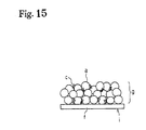
- a negative electrode i is manufactured by mixing the mixture e of the powdered electrode active substance a comprising powdered graphite, the binder polymer c and the solvent d into a slurry, applying it to the current-collecting member f, and drying to form the compound film g , as shown in Fig. 15.
- the mixing is performed for example by a planetary mixer as shown in Fig. 17.
- the mixture is held in a container, and a mixing blade is rotated so the mixture forms a slurry.
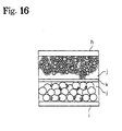
- a lithium secondary cell contains an electrolyte j between the positive electrode h and negative electrode i, a separator k being disposed in the electrolyte j, as shown in Fig. 16.
- the strength of the compound film g decreases, so cohesion between the electrode active substance a or electron-conducting assistant and the current-collecting member f gradually declines during repeated charges and discharges of the battery, and battery performance declines due to decrease of electron-conducting properties.
- Japanese Patent Laid-Open Hei 10-106540 discloses a method of forming the binder polymer c as a mesh.
- the binder polymer c which is used is a non-ion conducting polymer, so ions cannot penetrate or move through the binder polymer c . Therefore, in this case also, penetration of lithium ions into the electrode active substance a is blocked as in the case of a prior art electrode. As a result, the battery performance declines.
- Batteries are used for various types of electrical components, and they have to satisfy stringent safety criteria with regard to fire, etc.
- oxygen is generated if the LiCoO 2 is heated to high temperature and as there is a risk of explosion or fire if a large current flows due to a short-circuit, safety is a prime consideration.
- This invention further relates to a press-sliding mixer which treats a mixture of an ion-conducting polymer or ion-conducting polymer raw material and a powdered substance so as to coat the powdered substance with the ion-conducting polymer, the mixer comprising a container having a bottom surface for containing the mixture and a main blade which displaces relative to the bottom surface, the mixture being press-slid between the bottom surface and the main blade, a coating method wherein a mixture of an ion-conducting polymer or ion-conducting polymer raw material and powdered substance is press-slid so as to coat the ion-conducting polymer or ion-conducting polymer raw material on a powdered substance, a powdered substance coated with an ion-conducting polymer obtained by press-sliding a mixture of an ion-conducting polymer or ion-conducting polymer raw material and a powdered substance,
- Fig. 1 is a diagram when coating a powdered active substance with an ion-conducting polymer.
- Fig. 2 is a descriptive diagram of a pressure-sliding mixer.
- Fig. 3 is a schematic view of the press-sliding mixer wherein the bottom surface of a container is flat.
- Fig. 4 is another schematic view of the press-sliding mixer.
- Fig. 5 is a diagram showing the manufacture of an electrode structure comprising an electrode active substance which supplies ions.
- Fig. 6 is a diagram of an electrode structure comprising an electrically conducting substance wherein electricity moves between ions.
- Fig. 7 is a schematic view of a secondary cell.
- Fig. 8 is a front view of the press-sliding mixer.
- Fig. 9 is a lateral view of the press-sliding mixer.
- Fig. 10 is a descriptive diagram of a cohesion device.
- Fig. 11 is an electron micrograph of LiCoO 2 which has not received any processing.
- Fig. 12 is an electron micrograph of a positive electrode structure obtained in a third embodiment.
- Fig. 13 is a photograph of a secondary electronic image of the positive electrode structure obtained in the third embodiment.
- Fig. 14 is a diagram showing the manufacture of an electrode structure comprising an electrode active substance which supplies ions according to the prior art.
- Fig. 15 is a diagram of an electrode structure comprising an electrically conducting substance wherein electricity moves between ions according to the prior art.
- Fig. 16 is a schematic view of a secondary cell according to the prior art.
- Fig. 17 is a front view of the press-sliding mixer.
- a press-sliding mixer is a device which press-slides mixtures of the ion-conducting polymer or its raw material 121 with the powdered substance 11 so as to coat the ion-conducting polymer 12 on the powdered substance 11.
- the press-sliding mixer is shown, for example, in Fig. 2.
- the mixture 10 of the ion-conducting polymer 12 or its raw material with the powdered substance 11, or the mixture 10 comprising this mixture and a solvent or the like, is introduced into a container 21, and the main blade 22 is rotated. There is a gap between a base 211 of the container 21 and a bottom surface of the main blade 22.
- part of the mixture 10 enters the space between the base 211 of the container and the main blade 22, is subjected to press-sliding, and is kneaded. This process is repeated so that the ion-conducting polymer 12 or its raw material coats the powdered substance 11.
- a press-sliding mixer 2 may if necessary be provided with a dispersion blade 23 in the container 21.
- the dispersion blade 23 is rotated at high speed to disperse the press-slid mixture 10.
- the container 21 is provided for holding the mixture 10 which is press-slid and stirred.
- the bottom surface of the container 21 may be such as to permit press-sliding of the mixture 10, and may be slanting as in Fig. 2 or flat as in Fig. 3.
- the center part may be situated in a low position, and have a slope rising towards the circumference.
- the bottom 211 may be formed in the shape of, for example, a grinding mortar, and the angle of the bottom part 2111 may for example be 120 degrees.
- the bottom 211 of the container is wear-resistant, and is formed by thermal spraying with tungsten or carbide using SUS. Plural bottom parts 2111 of this type may also be formed on the bottom surface.
- the main blade 22 functions together with the bottom surface of the container 21, serving to press-slide and stir the mixture.
- the main blade may have a number of different shapes. For example, in Fig. 3 or Fig. 4(B), it is disk-shaped or plate-shaped and in Fig. 4(A), it is fashioned into a wide blade so as to provide a large surface area between the bottom surface of the container and the blade adjacent to it, thereby increasing the efficiency of press-sliding.
- the main blade is disk-shaped, for example, it has plural though holes 224 as is shown in Fig. 3(B) and notched groove 225 as is shown in Fig. 4(B). The mixture is transported to a gap between the bottom surface of the main blade 22 and the container via the through holes 224 or the notched grooves 225.
- the mixture adhering to the lateral surfaces of the container is removed, stirring efficiency can be increased.
- members adjacent to the lateral surfaces of the container for example scrapers 223, may be attached to the tip of the main blade as shown in Fig. 3 or Fig. 4.
- the scrapers 223 rotate together with the main blade so that mixture in the vicinity of the lateral surfaces of the container is scraped off, and is transported to the gap between the bottom surface of the container and the blade surface.
- press-sliding is performed with high efficiency.
- the tip of the main blade is to remove the mixture adhered to the lateral surface of the container and may be positioned away from the main blade for the independent operation.
- a shaft is attached in a position corresponding to the bottom part 2111 of the container 21 as shown for example in Fig. 2(B), and if the bottom surface of the container is slanting, it curves upwards along the bottom of the container from the bottom part 2111.
- the main blade 22 may comprise two blades attached from the center part as shown in Fig. 2(B), or it may comprise a larger number of blades, e.g. 10 or more, depending on the amount and type of mixture. Instead of a large number of blades, a wide blade having a wide base may also be used. This allows larger surface for the press-sliding action, thereby providing more efficient press-sliding.
- the main blade is rotated by a main motor 222.
- a sympathetic flow may also be set up in the mixture due to the rotation of the main blade, so sympathetic flow is prevented by reversing the main blade during the rotation. For example, forward rotation is performed for 10 seconds, the blade is stopped, and reverse rotation is then performed for 10 seconds. By repeating this action, press-sliding control is performed. Practically identical results for press-sliding were obtained when this back and forth reverse control was performed for approximately 30 minutes, and when rotation in the same direction was performed for approximately 3 hours. There are also many other rotation methods, for example the rotation angle can continuously be suitably varied like a sine curve, etc.
- the rotation speed of the main blade i.e., the number of rotations, is set low, for example to 120 rpm or less, when press-sliding is performed.
- the gap between the bottom surface of the container 21 and the base surface of the main blade 22 is set as narrow as is necessary for press-sliding the mixture, for example 15 mm or less. This distance depends on the capacity of the press-sliding mixer 2 and on the shape of the main blade, etc.
- the surface in the motion direction (press-sliding direction) of the main blade 22 is formed so that a pressing angle ⁇ relative to the bottom surface of the container 21 is an acute angle.
- a pressing angle ⁇ relative to the bottom surface of the container 21 is an acute angle.
- the cross-section of the main blade 22 is a reverse trapezoid as shown in Fig. 2(C)
- the pressing angle is from 3 degrees to 70 degrees.
- the cross-section of the main blade 22 may also be circular or have a rounded corner as shown in Fig. 2(D).
- the material of the main blade has wear-resistant properties, and is formed for example by thermal spraying with tungsten or carbide using SUS.
- the mixture 10 can be collected around the main shaft 221 by rotating the main shaft 221 in the reverse direction.
- the center parts of the main blade 22 are also disposed in positions of the bottom part corresponding to their number.
- Press-sliding is the action of sliding while pressing mixtures 10 of the ion-conducting polymer 12 or the raw material of the ion-conducting polymer 12 and the powdered substance 11 together. An external force is applied to the mixtures so that they cohere to each other and the particles rotate, and this process is performed repeatedly to obtain a press-sliding product.
- a rotation is given to the powdered substance 11, if necessary.
- the mixtures 10 are brought into mutual contact by applying an external force to the mixtures 10 between a main blade 22 and the bottom of a container, the mixtures 10 slide and rotate due to a rotation of the main blade 22, and an ion-conducting polymer or ion-conducting polymer raw material 121 is thereby coated on the powdered substance 11.
- This is performed repeatedly so that the ion-conducting polymer or ion-conducting polymer raw material 121 is adsorbed by the whole of the powdered substance, and the ion-conducting polymer or ion-conducting polymer raw material 121 covers the surface of the powdered substance 11.
- the dispersion blade 23 is intended to disperse the mixture 10 which has been press-slid by the main blade 22.
- the dispersion blade 23 is disposed in a position at which the mixture 10 can be dispersed, and it rotates at a high speed such as 1000-4000 rpm. Due to this high speed rotation, the ion-conducting polymer 12 or its raw material coated on the particle surfaces of the powdered substance 11 uniformly disperses through the whole of the powdered substance.
- the mixture adheres on the area surrounding the main shaft 221 of the main blade 22 when in firm mixing or low clay dispersion and tends to be ununiformed mixing.
- the dispersion blade 23 is positioned on the main shaft 221 of the main blade 22, rotating the same from the dry mixing stage to prevent the adhesion on the area surrounding the main shaft 221.
- the powdered substance 11 has a small particle size, and is a powdered electrode active substance or a powdered electrically-conducting substance used, for example, in secondary cell electrodes or a powdered large surface material with a large surface area used in an electric double layer capacitor.
- the powdered electrode active substance may be a material which permits insertion and separation of ions, or a ⁇ -conjugated electrically-conducting polymer material.
- Electrode active material used as the positive electrode in a non-aqueous electrolytic battery there is no particular limitation on the electrode active material used as the positive electrode in a non-aqueous electrolytic battery, but in the case of a rechargeable secondary cell, a chalcogen compound permitting insertion and separation of lithium ions or a complex chalcogen compound containing lithium may for example be used.
- the electrode active substance used as the negative electrode in a non-aqueous electrolyte battery there is no particular limitation on the electrode active substance used as the negative electrode in a non-aqueous electrolyte battery, but a material permitting insertion and separation of lithium ions may be used such as lithium metal, lithium alloy (alloys of lithium and aluminum, lead and indium, etc.), and carbon materials.
- Examples of ⁇ -conjugated conducting polymer materials are polyacetylenes, polyanilines, polypyrroles, polythiophenes, poly- p (para)-phenylenes, polycarbazoles, polyacenes and sulfur polymers.
- the powdered electrically-conducting substance increases the electrical conductivity of the electrode structure, there being no particular limitation thereon, but metal powders and carbon powder may be used.
- carbon powder pyrolytic carbon such as carbon black and its graphitization products, artificial and natural scaly graphite powder, and carbon fiber and its graphitization products, are suitable. Mixtures of these carbon powders may also be used.
- a powdered electrode substance with a large surface area is a powdered large surface material that may draw many ions on that surface.
- a preferable powdered large surface material has its specific surface area of 500m 2 /g or larger, more preferably 1000m 2 /g or larger, further more preferably 1500m 2 /g-3000m 2 /g, and its average particle diameter of 30 ⁇ m or lower, more preferably 5-30 ⁇ m carbon material. If the specific surface area and the average particle diameter are out of the above-specified range, and it may be difficult to secure a high electrostatic capacity and a low resistance electric double layer capacitor.
- a preferable powdered large surface material especially is an activated carbon resulting from activating the carbon material such as by a steam activating treatment and a fused KOH activating treatment.
- the activated carbon for example may be palm shell activated carbon, a phenol activated carbon, a petroleum coke type activated carbon, and polyacenes.
- One of the above activated carbon types or combination of two ore more activated carbon types may be employed.
- Phenol activated carbon, a petroleum coke type activated carbon, and a polyacenes are preferable since they provide a larger electrostatic capacity.
- the ion-conducting polymer is a polymer which can dissolve at least the lithium salts described hereafter at a concentration of at least 0.1M (moles/l), the polymer containing the lithium salt at a concentration of at least 0.1 M having an electrical conductivity of 10 -8 S (siemens)/cm at room temperature. It is to be particularly preferred that the ion-conducting polymer dissolves at least lithium salts to a concentration of 0.8M-1.5M, the resulting polymer solution having an electrical conductivity of 10 -3 S/cm - 10 -5 S/cm at room temperature.
- the lithium salt is at least one type of lithium salt having ClO 4 - , CF 3 SO 3 - , BF 4 - , PF 6 - , AsF 6 - , SbF 6 - , CF 3 CO 2 - or (CF 3 SO 2 ) 2 N - as anion.
- the ion-conducting polymer raw material is a substance which produces the ion-conducting polymer by cross-linking, etc., when energy is supplied externally.
- the energy may be heat, ultraviolet light, light or electron radiation.
- Electrode structures are used as electrodes in these electrical components such as a secondary cell and an electric double layer capacitor, and exchange electrical charges with ions or draw ions.
- they have a construction in which a powdered electrode active substance coated with an ion-conducting polymer, is made to adhere to a current-collecting member.
- they have a construction in which the powdered electrode active substance used for batteries or a powdered large surface material with a large surface area used for an electric double layer capacitor is made to adhere to a current-collecting member.
- Fig. 5 shows a process for manufacturing an electrode structure 1 wherein a powdered electrode substance, i.e., a powdered electrode active substance 11 comprising particles of a compound such as LiCoO 2 is coated with an ion-conducting polymer 12, and is made to adhere to a current-collecting member 13.
- Fig. 6 shows a process for manufacturing the electrode structure 1 wherein a powdered electrode substance, i.e., a powdered electrode active substance 11 having a form such as that of graphite or hard carbon is coated with the ion-conducting polymer 12, and is made to adhere to the current-collecting member 13.
- a powdered large surface material such as an activated carbon as the powdered large surface material such as an activated carbon as the powdered electrode substance may be coated with the ion-conducting polymer and is adhered to the current-collecting member to form an electrode structure of the electric double layer capacitor.
- Fig. 5 shows the case where the electrical conductivity of the powdered electrode active substance 11 is low.
- the electrical conductivity in the powdered electrode active substance and between the powdered electrode active substance 11 and current-collecting member 13, is increased and the current-collecting efficiency improved by mixing with a powdered electrically-conducting substance 14.
- the powdered electrically-conducting substance 14 may or may not be coated with the ion-conducting polymer.
- Coating refers to a state of contact wherein ions can easily migrate between the ion-conducting polymer 12 and the powdered electrode substance, i.e., the powdered electrode active substance 11 over their entire surfaces or the powdered large surface material over their entire surfaces.
- the ion-conducting polymer 12 is coated on the surface of the powdered electrode active substance 11 or the powdered large surface material so that the latter is covered by the ion-conducting polymer 12.
- the powdered electrode active substance 11 becomes more active the finer the particles of which it is comprised, but its activity can be suppressed to give greater stability by coating with the ion-conducting polymer 12.
- the layer of the coated ion-conducting polymer 12 is thick, conductivity decreases and current-collecting efficiency is poorer, so it is preferably thin.
- powdered electrode active substance 11 or the powdered electrically-conducting substance 14, or the powdered large surface material refers to a substance having a fine particle state. In some cases, it may refer to a state wherein a large number of substances having a fine particle state are agglomerated.
- the secondary cell comprises the ion-conducting substance disposed between two types of the electrode structures 1.
- the secondary cell is formed by introducing a liquid such as the electrolyte 14 between an electrode structure 101 of the positive electrode and an electrode structure 102 of the negative electrode, and disposing a separator 15 between them as shown for example in Fig. 7(A).
- a solid electrolyte substance such as an ion-conducting polymer 16 between the electrode structure 101 of the positive electrode and the electrode structure 102 of the negative electrode as shown in Fig. 7(B).
- the electric double layer capacitor has a construction in which the powdered large surface material is used to form a pair of electrode structures and an electrolyte substance is disposed between the pair of electrode structures.
- the main blade 22 in close contact with the mortar-shaped bottom surface of the container 21 of the press-sliding mixer 2 is rotated at low speed, and the mixture 10 of the ion-conducting polymer or its raw material 121 and the powdered substance 11 is introduced into the container 21.
- the mixture 10 is pressed into the gap between the bottom surface of the container 21 and the main blade 22, the ion-conducting polymer or its raw material 121 is adsorbed on the surface and voids of the powdered substance 11.
- a cycle takes place wherein the press-slid mixture 10 temporarily rises up the mortar-shaped bottom surface from the bottom 211 of the container 21 due to the rotation of the main blade 22, then the mixture 10 introduced into the container 21 falls down relative to the risen part and is press-slid on the bottom surface of the container.
- the mixture 10 in the container is press-slid an equivalent number of times.
- the press-sliding mixer is supported on the supporting platform 24, the container 21 is raised by the handle 241, and the device is controlled by the control panel 25.
- the powdered substance 11 (containing an additive) is measured out, and introduced from a powdered substance input port 34.
- a measuring hopper or the like is installed above the powdered substance input port 34 for storage and measurement, and a valve 341 of the powdered substance input port is automatically opened by an input command.
- a discharge port 32 fitted with an aspiration filter 322 is opened alone so that only air is discharged.
- a valve 331 of an input port 33 for the ion-conducting polymer or its raw material is opened, and the polymer or its raw material is measured out manually or automatically and introduced into the container in the same way as the powdered substance.
- the input valves 331, 341 are closed. Further, if warm water at 30 °C is recirculated through a jacket 213 of the container to promote wetting of the powdered substance and the ion-conducting polymer or its raw material, the wetting efficiency can be improved. However, when a penetration-assisting solvent is used, processing is performed at ordinary temperature.
- the main motor 222 is rotated at a low speed of about 10 rpm, the mixture 10 of the ion-conducting polymer or its raw material and the powdered substance is press-slid between the bottom surface of the container 21 and the main blade 22, and the ion-conducting polymer or its raw material gradually begins to penetrate the powdered substance.
- the press-slid mixture 10 rises up the container at the tip of the main blade 22, the mixture 10 falls down from above the center part of the container, and a turning over action takes place in the container over its entire circumference. This is repeated regularly so that the whole mixture is uniformly press-slid.
- the rotation speed of the main shaft 221 is automatically or manually increased to 60 rpm, and when wetting of the mixture 10 has reached effectively half of the surface area, a vacuum pump 353 of a degassing port 35 is operated, a degassing valve 351 is opened, and degassing is performed via a filter 352 for about 1 hour.
- the main blade 22 press-slides the mixture 10 while degassing is performed, so wetting and penetration dispersion of the ion-conducting polymer or its raw material in the powdered substance is promoted.
- the dispersion blade When penetration degassing has reached about 70% after degassing for approximately 1 hour, the dispersion blade is rotated at 2800 rpm to promote dispersion.
- the powdered substance input port valve 341, the ion-conducting polymer input port valve 331, a discharge port valve 321 and the degassing port valve 351 are closed, the mixture 10 is pressurized by introducing an air pressure according to the viscosity of the mixture 10 from a pressurizing port 31, for example an air pressure of approximately 5kg/cm 2 , and it is then extracted from a discharge port 36.
- the mixture 10 collects in the center part of the container bottom, so the mixture 10 can be discharged naturally from the discharge port 36.
- a solvent is added to the press-slid mixture to liquefy it to a paste which is applied to the current-collecting member, and the product is dried to evaporate the solvent.
- the solvent can be added to the mixture from the beginning and made into a paste as it is subjected to press-sliding.
- the resulting substance which is press-slid and paste-like is thinly applied to the surface of the current-collecting member. After application, the solvent evaporates and dries to obtain the electrode structure.
- Devices which are suitable for applying the press-slid substance to the current-collecting member include, for example, a doctor knife applicator.
- the applied press-slid substance may be pressed against the current-collecting member to make it adhere to it more strongly.
- a bonding device 4 may for example be used.
- the press-slid substance can be made to adhere to the current-collecting member by gripping the electrode structure 1 comprising the current-collecting member coated with the press-slid substance between pressure rollers 41, applying a pressure to backup rollers 42 by a pressure device 43, and rotating the rollers.
- the press-slid substance was paste-like.
- 0.254 weight parts of polymeric MDI, MR-200 (NPU Co.) was added to the press-slid substance, and the mixture stirred for 5 minutes in the press-sliding mixer.
- the press-slid substance was removed, transferred to aluminum foil of thickness 20 ⁇ m, and spread by a doctor knife applicator of 100 ⁇ m gap.
- the resulting product was left at room temperature for 15 minutes, and then heated at 80 °C for 1 hour.
- the thickness of the positive electrode structure obtained was 80 ⁇ m.
- the same effectiveness is seen when spreading by a doctor knife applicator of 200 ⁇ m gap.
- LiCoO 2 of average particle size 5 ⁇ m which is a powdered electrode active substance
- 0.341 weight parts of an ion-conducting polymer raw material (A1) and 3.0 weight parts of acetonitrile were introduced into a press-sliding mixer (capacity 300cc), and the mixture press-slid for 7 hours.
- the press-slid substance was paste-like.
- 0.159 weight parts of polymeric MDI, MR-200 (NPU Co.) was added, and the mixture press-slid for 5 minutes.
- the press-slid substance was removed, transferred to aluminum foil of thickness 20 ⁇ m, and spread by a doctor knife applicator of 100 ⁇ m gap.
- the resulting product was left at room temperature for 15 minutes, and heated at 80 °C for 1 hour.
- the thickness of the electrode obtained was 80 ⁇ m.
- the same effectiveness is seen when spreading by a doctor knife applicator of 200 ⁇ m gap.
- the press-slid substance was paste-like.
- a solution of 0.01 weight parts of 2,2'-azobis (2,4-dimethylvaleronitrile) and 0.5 weight parts of a (1/1) vol liquid electrolyte of ethylene carbonate (EC)/diethylene carbonate (DEC) was added to the press-slid substance, and the mixture further press-slid for 5 minutes.
- the press-slid substance was removed, transferred to aluminum foil of thickness 20 ⁇ m, and spread by a doctor knife applicator of 100 ⁇ m gap.
- the resulting product was left at room temperature for 15 minutes, and heated at 80 °C for 3 hours.
- the thickness of the electrode obtained was 80 ⁇ m.
- the same effectiveness may be expected by the use of 0.5 weight parts of the ion-conducting polymer raw material (A2), 0.003 weight parts of 2,2'-azobis (2,4-dimethylvaleronitrile), and by spreading a doctor knife applicator of 200 ⁇ m gap.
- the resulting product was left at room temperature for 15 minutes, and heated at 80°C for 1 hour.
- the thickness of the electrode obtained was 80 ⁇ m.
- the same effectiveness may be expected by the use of 10.0 weight parts of the acetonitrile and spreading a doctor knife applicator of 250 ⁇ m gap.
- the press-slid substance was removed, transferred to copper foil of thickness 20 ⁇ m, and spread by a doctor knife applicator of 100 ⁇ m gap.
- the resulting product was left at room temperature for 15 minutes, and heated at 80°C for 3 hours.
- the thickness of the electrode obtained was 80 ⁇ m.
- the same effectiveness may be expected by the use of 0.8 weight parts of the ion-conducting polymer raw material (A2), 10.0 weight parts of acetonitrile, 0.004 weight parts of 2,2'-azobis (2,4-dimethylvaleronitrile), and by spreading a doctor knife applicator of 250 ⁇ m gap.
- Fig. 11 shows 5000 times magnified an electron micrograph of LiCoO 2 of average particle size 5 ⁇ m which had not received any processing.
- the corners of the compound particles of LiCoO 2 are square and clearly visible.
- the electron micrograph of Fig. 12 is an electron micrograph of the positive electrode structure obtained in Example 3.
- the corners of the compound particles of LiCoO 2 are smooth, and appear to be covered by a film.
- the LiCoO 2 particles in Fig. 12 are uniformly covered with a film of ion-conducting polymer.
- Fig. 13 shows 5000 times magnified a two-dimensional electronic image of the surface of the positive electrode structure obtained in Example 3 measured by a Shimadzu EPMA-8705 Electron Probe Micro-Analyzer.
- the particles of Fig. 13 have smooth corners and appear to be covered by a coating.
- the resulting product was then heated to evaporate n-methylpyrrolidine.
- the thickness of the electrode obtained was 80 ⁇ m.
- the same result is expected by the use of 5.0 weight parts of n-methylpyrrolidine and spreading a doctor knife applicator of 200 ⁇ m gap.
- a test lithium ion secondary cell was manufactured using the positive electrode structures manufactured in the examples and comparative examples.
- the positive electrode and negative electrode were both cut out to have an electrode surface area of 4cm 2 .
- Completely solid polymer (all polymer), polymer gel electrolyte (polymer gel), liquid electrolyte (liquid) and a separator were sandwiched between the positive electrode and negative electrode to manufacture the test cell.
- the concentration of lithium salt (supporting electrolyte salt) in the respective electrolytes was arranged to be 1 M. This cell was charged at 0.3mA per 1cm 2 of electrolyte surface area to 4.1V, and after allowing to stand for 15 minutes, it was discharged at 0.3mA/cm 2 to 2.7V.
- Table 4 shows the contents of the electrolytes listed in Table 3. The same effectiveness is expected if the thickness of the electrolyte is 20 ⁇ m at P1-AP4 and 30 ⁇ m at PG1-PG2.
- test cells using the positive electrode and negative electrode of this invention could be successfully charged and discharged.
- test cells using the electrodes of the comparative examples and a solid or gel electrolyte could not be charged/discharged, although test cells using liquid electrolytes and gel electrolytes could be charged/discharged.
- An electrode structure for capacitor is manufactured by adding the carbon black as the powdered conducting substance in a phenol activated carbon (manufactured by Kansai Kagaku Corporation) as the powdered electrode substance; dry-mixing with a mixing container; adding the polymer A1 as the binder to be mixed; adding NMP (N methylpyrolidone) as the solvent to be mixed; applying on the current-collecting member by the doctor knife applicator; and drying.
- the thickness of the electrode is 75 ⁇ .
- This invention makes it possible to obtain a device wherein a powdered substance is efficiently coated by an ion-conducting polymer.
- This invention makes it possible to obtain a method whereby a powdered substance is efficiently coated by an ion- conducting polymer.
- This invention further makes it possible to obtain a powdered substance coated by an ion-conducting polymer.
- Japanese Patent Application Laid-Open No. 8-225626 100 ⁇ m AP2 All polymer Cyanoethylated/dihydroxypropylated cellulose and methacryl polymer 3D cross-linked structure (e.g. Japanese Patent Application Laid-Open No. 8-225626) 100 ⁇ m AP3 All polymer High viscosity polyurethane electrolyte (e.g. Japanese Patent Application No. 11-78085) 100 ⁇ m AP4 All polymer Cyanoethylated/dihydroxypropylated polyvinyl alcohol (e.g. Japanese Patent Application No.
Landscapes
- Engineering & Computer Science (AREA)
- Chemical & Material Sciences (AREA)
- Power Engineering (AREA)
- Chemical Kinetics & Catalysis (AREA)
- Manufacturing & Machinery (AREA)
- Electrochemistry (AREA)
- General Chemical & Material Sciences (AREA)
- Microelectronics & Electronic Packaging (AREA)
- Materials Engineering (AREA)
- Dispersion Chemistry (AREA)
- Inorganic Chemistry (AREA)
- Battery Electrode And Active Subsutance (AREA)
- Application Of Or Painting With Fluid Materials (AREA)
Abstract
Description
| Ion-conducting polymer raw material (A1) | |
| Substance | Mixing ratio (weight parts) |
| Trifunctional (propylene glycol/ethylene glycol) random copolymer, SANNIX FA-103 (PO/EO=2/8, Mw=3,282, Sanyo Chemical Industries, Ltd.) | 8.36 |
| Trifunctional polyol, 1,4-butadiol | 0.34 |
| Ethylene cyanohydrin | 1.27 |
| Reaction catalyst NC-IM (Sankyo Air Products K.K.) | 0.03 |
| Total | 10 |
| Ion-conducting polymer raw material (A2) | |
| Substance | Mixing ratio (weight parts) |
| Cyanoethylated/dihydroxypropylated polyvinyl alcohol | 0.625 |
| Methoxypolyethyleneglycol methacrylate (mol. wt. 468) | 3.125 |
| Trimethylolpropanetri methacrylate | 6.25 |
| Total | 10 |
| Charging/discharging test results | ||||
| No | Positive electrode | Negative electrode | Electrolyte | Charging/discharging test result |
| 1 | Example 1 | Example 5 | AP1 | Possible |
| 2 | Example 1 | Example 5 | AP2 | Possible |
| 3 | Example 1 | Example 5 | AP3 | Possible |
| 4 | Example 1 | Example 5 | AP4 | Possible |
| 5 | Example 1 | Example 5 | PG1 | Possible |
| 6 | Example 1 | Example 5 | PG2 | Possible |
| 7 | Example 1 | Example 5 | L1 | Possible |
| 8 | Example 2 | Example 5 | AP3 | Possible |
| 9 | Example 2 | Example 6 | PG2 | Possible |
| 10 | Example 4 | Example 5 | AP3 | Possible |
| 11 | Example 4 | Example 6 | PG2 | Possible |
| 12 | Comparative example 1 | Comparative example 2 | AP1 | Charging/discharging impossible |
| 13 | Comparative example 1 | Comparative example 2 | AP2 | Charging/discharging impossible |
| 14 | Comparative example 1 | Comparative example 2 | AP3 | Charging/discharging impossible |
| 15 | Comparative example 1 | Comparative example 2 | AP4 | Charging/discharging impossible |
| 16 | Comparative example 1 | Comparative example 2 | PG1 | Charging/discharging impossible |
| 17 | Comparative example 1 | Comparative example 2 | PG2 | Charging/discharging impossible |
| 18 | Comparative example 1 | Comparative example 2 | L1 | Possible |
| Electrolyte used in test | |||
| Symbol | Type | Composition | Thicknes s |
| AP1 | All polymer | Cyanoethylated/dihydroxypropylated cellulose (e.g. Japanese Patent Application Laid-Open No. 8-225626) | 100 µm |
| AP2 | All polymer | Cyanoethylated/dihydroxypropylated cellulose and methacryl polymer 3D cross-linked structure (e.g. Japanese Patent Application Laid-Open No. 8-225626) | 100 µm |
| AP3 | All polymer | High viscosity polyurethane electrolyte (e.g. Japanese Patent Application No. 11-78085) | 100 µm |
| AP4 | All polymer | Cyanoethylated/dihydroxypropylated polyvinyl alcohol (e.g. Japanese Patent Application No. 11-78086) | 100 µm |
| PG1 | Polymer gel | Cyanoethylated/dihydroxypropylated polyvinyl alcohol and methacryl polymer 3D cross-linked structure containing 50% ethylene carbonate (EC)/diethylene carbonate (DEC) = (1/1) vol liquid electrolyte (e.g. Japanese Patent Application No. 11-78087) | 100 µm |
| PG2 | Polymer gel | High viscosity polyurethane electrolyte containing 50% ethylene carbonate (EC)/diethylene carbonate (DEC) = (1/1) vol liquid electrolyte (e.g. Japanese Patent Application No. 11-78085) | 100 µm |
| L1 | Liquid | Impregnation of ethylene carbonate (EC)/diethylene carbonate (DEC) = (1/1) vol solution in polyethylene separator | 23 µm |
Claims (20)
- A press-sliding mixer which processes a mixture of an ion-conducting polymer or ion-conducting polymer raw material and a powdered substance so as to coat the powdered substance with the ion-conducting polymer, comprising a container having a bottom surface for containing the mixture and a main blade which displaces relative to the bottom surface, wherein the mixture is press-slid between the bottom surface and the main blade.
- A press-sliding mixer as defined in Claim 1, wherein there is an effectively constant gap between the main blade and the bottom surface.
- A press-sliding mixer as defined in Claim 1, further comprises a tip of said main blade for removing the mixture adhered to the lateral surface of said container.
- A press-sliding mixer as defined in Claim 3, wherein said tip of main blade is disposed at the position facing said lateral surface of container of said main blade.
- A press-sliding mixer as defined in Claim 1, wherein said main blade is disk-shaped.
- A press-sliding mixer as defined in Claim 5, wherein said disk-shaped main blade has at least one through hole or notched groove.
- A press-sliding mixer as defined in Claim 1, wherein said main blade is a wide blade.
- A press-sliding mixer as defined in Claim 1, wherein a rotational direction of said main blade is repeatedly reversed.
- A press-sliding mixer as defined in Claim 1, wherein the bottom surface has a bottom part with a low part and a slope which increases from the bottom part to a circumferential part, and the main blade is disposed above the bottom part and rotates around the bottom part as center.
- A press-sliding mixer as defined in Claim 1, wherein a surface in the motion direction of the main blade is formed at an acute angle to the bottom surface of the container.
- A press-sliding mixer as defined in Claim 1, wherein a surface opposite to the motion direction of the main blade is formed effectively perpendicular to or at an obtuse angle to the bottom surface of the container.
- A press-sliding mixer as defined in Claim 1, comprising a dispersion blade in the container.
- A coating method wherein a mixture of an ion-conducting polymer or ion-conducting polymer raw material and a powdered substance is press-slid so as to make the ion-conducting polymer or ion-conducting polymer raw material adhere to a powdered substance.
- A coating method for coating a powdered substance with an ion-conducting polymer as defined in Claim 13, wherein a solvent is added to a mixture.
- A coating method for coating a powdered substance with an ion-conducting polymer as defined in Claim 13, wherein the mixture is contained in a container and the mixture is press-slid by a main blade against the bottom surface of the container.
- A coating method for coating a powdered substance with an ion-conducting polymer as defined in Claim 13, wherein the mixture is contained in a container, the mixture is press-slid by a main blade against the bottom surface of the container, and the mixture is dispersed by a dispersion blade.
- A powdered substance coated with an ion-conducting polymer obtained by press-sliding a mixture of an ion-conducting polymer or ion-conducting polymer raw material and a powdered substance.
- A powdered substance coated with an ion-conducting polymer as defined in Claim 17, wherein the powdered substance is a powdered electrode active substance or a powdered large surface material.
- A powdered substance formed by coating a powdered electrode active substance used in an electrode structure of a secondary cell with an ion-conducting polymer.
- A powdered substance formed by coating a powdered electrode active substance used in an electrode structure of an electric double layer capacitor.
Applications Claiming Priority (3)
| Application Number | Priority Date | Filing Date | Title |
|---|---|---|---|
| JP26250199 | 1999-08-12 | ||
| JP26250199 | 1999-08-12 | ||
| PCT/JP2000/005397 WO2001013447A1 (en) | 1999-08-12 | 2000-08-11 | Press-slide kneader, method for coating with ionic-conductive polymer, and powdery material |
Publications (2)
| Publication Number | Publication Date |
|---|---|
| EP1130667A1 true EP1130667A1 (en) | 2001-09-05 |
| EP1130667A4 EP1130667A4 (en) | 2004-09-15 |
Family
ID=17376688
Family Applications (1)
| Application Number | Title | Priority Date | Filing Date |
|---|---|---|---|
| EP00951953A Withdrawn EP1130667A4 (en) | 1999-08-12 | 2000-08-11 | PRESS SLIDING MIXER, METHOD FOR COATING WITH IONIC-CONDUCTING POLYMER AND POWDER MATERIAL |
Country Status (7)
| Country | Link |
|---|---|
| EP (1) | EP1130667A4 (en) |
| KR (1) | KR20010099678A (en) |
| CN (1) | CN1248341C (en) |
| AU (1) | AU6474800A (en) |
| CA (1) | CA2346180A1 (en) |
| TW (1) | TW563268B (en) |
| WO (1) | WO2001013447A1 (en) |
Cited By (3)
| Publication number | Priority date | Publication date | Assignee | Title |
|---|---|---|---|---|
| EP1231652A4 (en) * | 1999-09-22 | 2006-09-13 | Nisshin Spinning | ELECTRODE STRUCTURE AND ROLLING DEVICE FOR MANUFACTURING THIS STRUCTURE |
| DE102008024511B4 (en) * | 2007-05-21 | 2010-07-01 | Daido Metal Co. Ltd., Nagoya | Method and device for producing a polarizable electrode for a double-layer electric capacitor |
| US11955280B2 (en) | 2018-10-29 | 2024-04-09 | PolyJoule, Inc. | High yield storage materials |
Families Citing this family (10)
| Publication number | Priority date | Publication date | Assignee | Title |
|---|---|---|---|---|
| US6878487B2 (en) * | 2001-09-05 | 2005-04-12 | Samsung Sdi, Co., Ltd. | Active material for battery and method of preparing same |
| RU2403975C1 (en) * | 2009-08-18 | 2010-11-20 | Закрытое Акционерное Общество "Твин Трейдинг Компани" | Roll homogeniser-crusher |
| TWI482340B (en) | 2011-12-14 | 2015-04-21 | Ind Tech Res Inst | Electrode assembly of lithium secondary battery |
| JP6413584B2 (en) * | 2014-10-06 | 2018-10-31 | 株式会社豊田自動織機 | Kneading equipment |
| CN105620022A (en) * | 2015-12-31 | 2016-06-01 | 苏州恩欧西精密机械制造有限公司 | Solder paste tank for printing machine |
| JP6947049B2 (en) * | 2018-01-18 | 2021-10-13 | トヨタ自動車株式会社 | How to clean the kneader |
| CN109758960B (en) * | 2019-03-07 | 2020-09-29 | 广东宏工物料自动化系统有限公司 | Lithium ion battery positive and negative electrode slurry mixing production system and slurry preparation process |
| KR102651203B1 (en) | 2019-11-21 | 2024-03-26 | 주식회사 엘지화학 | Impeller for stirrer and stirrer |
| JP7586465B2 (en) | 2020-08-25 | 2024-11-19 | 株式会社新日南 | Granulator |
| CN113144672B (en) * | 2021-05-18 | 2022-08-16 | 许昌学院 | Agitating unit is used in traditional chinese medicine extraction convenient to sediment liquid separation |
Family Cites Families (12)
| Publication number | Priority date | Publication date | Assignee | Title |
|---|---|---|---|---|
| JPS57127431A (en) * | 1981-01-29 | 1982-08-07 | Nitsukuu Kogyo Kk | Vacuum mixing and defoaming machine |
| JPS57130539A (en) * | 1981-02-02 | 1982-08-13 | Kitagawa Tekkosho:Kk | Structure for arranging mixing blade group of pan shaped mixer |
| JPS6359341A (en) * | 1986-08-30 | 1988-03-15 | Toyoda Gosei Co Ltd | Stirring impeller |
| JP3335366B2 (en) * | 1991-06-20 | 2002-10-15 | 三菱化学株式会社 | Electrodes for secondary batteries |
| JP3424235B2 (en) * | 1991-06-26 | 2003-07-07 | 松下電器産業株式会社 | Solid electrode composition |
| US5221055A (en) * | 1992-09-09 | 1993-06-22 | Kuan Chen Y | Grinding mixer |
| US5604057A (en) * | 1995-11-27 | 1997-02-18 | General Motors Corporation | Secondary cell having a lithium intercolating manganese oxide |
| JP3702318B2 (en) * | 1996-02-09 | 2005-10-05 | 日本電池株式会社 | Non-aqueous electrolyte battery electrode and non-aqueous electrolyte battery using the electrode |
| JP4187282B2 (en) * | 1996-06-10 | 2008-11-26 | 日立マクセル株式会社 | Lithium ion secondary battery |
| JP3506860B2 (en) * | 1996-12-05 | 2004-03-15 | 東芝電池株式会社 | Manufacturing method of non-aqueous solvent secondary battery |
| KR100527322B1 (en) * | 1997-05-06 | 2006-01-27 | 소니 가부시끼 가이샤 | Sheet for Forming a Polymer Gel Electrolyte, Polymer Gel Electrolyte Using Such a Sheet and Method for the Manufacture Thereof |
| JPH1197027A (en) * | 1997-09-18 | 1999-04-09 | Ricoh Co Ltd | Non-aqueous electrolyte secondary battery |
-
2000
- 2000-08-11 KR KR1020017004414A patent/KR20010099678A/en not_active Withdrawn
- 2000-08-11 CA CA002346180A patent/CA2346180A1/en not_active Abandoned
- 2000-08-11 AU AU64748/00A patent/AU6474800A/en not_active Abandoned
- 2000-08-11 CN CNB008016887A patent/CN1248341C/en not_active Expired - Fee Related
- 2000-08-11 WO PCT/JP2000/005397 patent/WO2001013447A1/en not_active Ceased
- 2000-08-11 TW TW089116200A patent/TW563268B/en not_active IP Right Cessation
- 2000-08-11 EP EP00951953A patent/EP1130667A4/en not_active Withdrawn
Cited By (5)
| Publication number | Priority date | Publication date | Assignee | Title |
|---|---|---|---|---|
| EP1231652A4 (en) * | 1999-09-22 | 2006-09-13 | Nisshin Spinning | ELECTRODE STRUCTURE AND ROLLING DEVICE FOR MANUFACTURING THIS STRUCTURE |
| DE102008024511B4 (en) * | 2007-05-21 | 2010-07-01 | Daido Metal Co. Ltd., Nagoya | Method and device for producing a polarizable electrode for a double-layer electric capacitor |
| US8197119B2 (en) | 2007-05-21 | 2012-06-12 | Daido Metal Company Ltd. | Method and apparatus for manufacturing polarizable electrode for electric double layer capacitor |
| US11955280B2 (en) | 2018-10-29 | 2024-04-09 | PolyJoule, Inc. | High yield storage materials |
| US12300434B2 (en) | 2018-10-29 | 2025-05-13 | PolyJoule, Inc. | High yield storage materials |
Also Published As
| Publication number | Publication date |
|---|---|
| EP1130667A4 (en) | 2004-09-15 |
| KR20010099678A (en) | 2001-11-09 |
| CA2346180A1 (en) | 2001-02-22 |
| CN1248341C (en) | 2006-03-29 |
| WO2001013447A1 (en) | 2001-02-22 |
| CN1320283A (en) | 2001-10-31 |
| TW563268B (en) | 2003-11-21 |
| AU6474800A (en) | 2001-03-13 |
Similar Documents
| Publication | Publication Date | Title |
|---|---|---|
| EP1126536B1 (en) | Multi-layer electrode structure, and method of manufacturing same | |
| JP3780530B2 (en) | Electric double layer capacitor and manufacturing method thereof | |
| EP1130667A1 (en) | Press-slide kneader, method for coating with ionic-conductive polymer, and powdery material | |
| WO1999019924A1 (en) | Batteries with porous components | |
| EP1231652A1 (en) | Electrode structure, and rolling machine for working electrode structure | |
| JP2023063336A (en) | solid state battery | |
| US20040234677A1 (en) | Mixer for coating an ion-conducting polymer on a powdered substance and method for coating the same | |
| EP1969657A2 (en) | Cathode for battery | |
| EP1130662A1 (en) | Electrode structure, electric component and production methods | |
| EP1160896A2 (en) | Electrode structure, battery and electrical double-layer capacitor and method of manufacturing same | |
| Ahn et al. | Synthesis of Li conductive polymer layer on 3D structured S cathode by photo-polymerization for Li–S batteries | |
| EP1143543A2 (en) | Electrode structure, battery and electrical double-layer capacitor and method of manufacturing same | |
| JP5251157B2 (en) | Method for producing electrode plate for non-aqueous electrolyte secondary battery | |
| CN1659727A (en) | Electrode active material mixed with conductive material, manufacturing method thereof, electrode structure, secondary battery | |
| KR20230044783A (en) | Apparatus for coating electrode and manufacturing method of electrode using the same | |
| JP2009230862A (en) | Method of manufacturing electrode plate for nonaqueous electrolyte secondary battery | |
| JPWO2001013447A1 (en) | Pressurized sliding kneading device, ion-conductive polymer coating method, and powdered material | |
| JPWO2001013444A1 (en) | Electrode structure, electrical component, and manufacturing method | |
| CN118511318A (en) | Method for producing particles for all-solid battery electrode, and all-solid battery electrode |
Legal Events
| Date | Code | Title | Description |
|---|---|---|---|
| PUAI | Public reference made under article 153(3) epc to a published international application that has entered the european phase |
Free format text: ORIGINAL CODE: 0009012 |
|
| 17P | Request for examination filed |
Effective date: 20010510 |
|
| AK | Designated contracting states |
Kind code of ref document: A1 Designated state(s): AT BE CH CY DE DK ES FI FR GB GR IE IT LI LU MC NL PT SE |
|
| AX | Request for extension of the european patent |
Free format text: AL;LT;LV;MK;RO;SI |
|
| RIC1 | Information provided on ipc code assigned before grant |
Ipc: 7B 01F 15/00 B Ipc: 7B 01F 13/10 B Ipc: 7H 01G 9/00 B Ipc: 7B 01F 7/26 A Ipc: 7B 01F 7/16 B |
|
| RIC1 | Information provided on ipc code assigned before grant |
Ipc: 7H 01G 9/04 B Ipc: 7B 01F 7/26 A Ipc: 7B 01F 13/10 B Ipc: 7B 01F 7/16 B Ipc: 7H 01M 10/04 B Ipc: 7H 01M 4/02 B Ipc: 7H 01G 9/00 B Ipc: 7B 01F 15/00 B |
|
| A4 | Supplementary search report drawn up and despatched |
Effective date: 20040728 |
|
| 17Q | First examination report despatched |
Effective date: 20050201 |
|
| STAA | Information on the status of an ep patent application or granted ep patent |
Free format text: STATUS: THE APPLICATION HAS BEEN WITHDRAWN |
|
| 18W | Application withdrawn |
Effective date: 20050811 |