EP1130539A2 - Improvements in automated and semiautomated printmask generation for incremental printing - Google Patents
Improvements in automated and semiautomated printmask generation for incremental printing Download PDFInfo
- Publication number
- EP1130539A2 EP1130539A2 EP00117780A EP00117780A EP1130539A2 EP 1130539 A2 EP1130539 A2 EP 1130539A2 EP 00117780 A EP00117780 A EP 00117780A EP 00117780 A EP00117780 A EP 00117780A EP 1130539 A2 EP1130539 A2 EP 1130539A2
- Authority
- EP
- European Patent Office
- Prior art keywords
- printmask
- mask
- matrix
- stack
- backup
- Prior art date
- Legal status (The legal status is an assumption and is not a legal conclusion. Google has not performed a legal analysis and makes no representation as to the accuracy of the status listed.)
- Granted
Links
Images



Classifications
-
- H—ELECTRICITY
- H04—ELECTRIC COMMUNICATION TECHNIQUE
- H04N—PICTORIAL COMMUNICATION, e.g. TELEVISION
- H04N1/00—Scanning, transmission or reproduction of documents or the like, e.g. facsimile transmission; Details thereof
- H04N1/04—Scanning arrangements, i.e. arrangements for the displacement of active reading or reproducing elements relative to the original or reproducing medium, or vice versa
- H04N1/12—Scanning arrangements, i.e. arrangements for the displacement of active reading or reproducing elements relative to the original or reproducing medium, or vice versa using the sheet-feed movement or the medium-advance or the drum-rotation movement as the slow scanning component, e.g. arrangements for the main-scanning
- H04N1/126—Arrangements for the main scanning
- H04N1/128—Arrangements for the main scanning using a scanning head arranged for linear reciprocating motion
-
- G—PHYSICS
- G06—COMPUTING OR CALCULATING; COUNTING
- G06K—GRAPHICAL DATA READING; PRESENTATION OF DATA; RECORD CARRIERS; HANDLING RECORD CARRIERS
- G06K15/00—Arrangements for producing a permanent visual presentation of the output data, e.g. computer output printers
- G06K15/02—Arrangements for producing a permanent visual presentation of the output data, e.g. computer output printers using printers
- G06K15/10—Arrangements for producing a permanent visual presentation of the output data, e.g. computer output printers using printers by matrix printers
- G06K15/102—Arrangements for producing a permanent visual presentation of the output data, e.g. computer output printers using printers by matrix printers using ink jet print heads
- G06K15/105—Multipass or interlaced printing
- G06K15/107—Mask selection
-
- H—ELECTRICITY
- H04—ELECTRIC COMMUNICATION TECHNIQUE
- H04N—PICTORIAL COMMUNICATION, e.g. TELEVISION
- H04N1/00—Scanning, transmission or reproduction of documents or the like, e.g. facsimile transmission; Details thereof
- H04N1/04—Scanning arrangements, i.e. arrangements for the displacement of active reading or reproducing elements relative to the original or reproducing medium, or vice versa
- H04N1/19—Scanning arrangements, i.e. arrangements for the displacement of active reading or reproducing elements relative to the original or reproducing medium, or vice versa using multi-element arrays
- H04N1/1906—Arrangements for performing substitution scanning for a defective element
-
- H—ELECTRICITY
- H04—ELECTRIC COMMUNICATION TECHNIQUE
- H04N—PICTORIAL COMMUNICATION, e.g. TELEVISION
- H04N1/00—Scanning, transmission or reproduction of documents or the like, e.g. facsimile transmission; Details thereof
- H04N1/04—Scanning arrangements, i.e. arrangements for the displacement of active reading or reproducing elements relative to the original or reproducing medium, or vice versa
- H04N1/19—Scanning arrangements, i.e. arrangements for the displacement of active reading or reproducing elements relative to the original or reproducing medium, or vice versa using multi-element arrays
- H04N1/191—Scanning arrangements, i.e. arrangements for the displacement of active reading or reproducing elements relative to the original or reproducing medium, or vice versa using multi-element arrays the array comprising a one-dimensional [1D] array
- H04N1/1911—Simultaneously or substantially simultaneously scanning picture elements on more than one main scanning line, e.g. scanning in swaths
-
- G—PHYSICS
- G06—COMPUTING OR CALCULATING; COUNTING
- G06K—GRAPHICAL DATA READING; PRESENTATION OF DATA; RECORD CARRIERS; HANDLING RECORD CARRIERS
- G06K2215/00—Arrangements for producing a permanent visual presentation of the output data
- G06K2215/0082—Architecture adapted for a particular function
- G06K2215/0085—Error recovery
-
- G—PHYSICS
- G06—COMPUTING OR CALCULATING; COUNTING
- G06K—GRAPHICAL DATA READING; PRESENTATION OF DATA; RECORD CARRIERS; HANDLING RECORD CARRIERS
- G06K2215/00—Arrangements for producing a permanent visual presentation of the output data
- G06K2215/111—Arrangements for producing a permanent visual presentation of the output data with overlapping swaths
Definitions
- This invention relates generally to machines and procedures for printing text or graphics on printing media such as paper, transparency stock, or other glossy media; and more particularly to a scanning thermal-inkjet machine and method that construct text or images from individual ink spots created on a printing medium, in a two-dimensional pixel array.
- the invention employs print-mode techniques to optimize image quality.
- Printmasks are used to determine the pass number in which a halftone dot is formed by an inkjet on the paper. Modern inkjet printers have the capability to detect defective nozzles on-line. In order to compensate for the defective nozzle the printmask has to be redesigned, or at least modified.
- the last stage of the inkjet printing pipeline consists of determining the pass number in which inkdrops allocated by the halftoning stage will be laid on the paper.
- the goal is, usually, to make sure that neighboring dots are laid as distant on the time axis, as is made possible by the number of passes allocated to the print-mode.
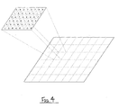
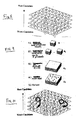
- the pass-number allocation is technically achieved using an integer matrix of pass numbers, called printmask, which is placed in a periodically repetitive manner on the halftone pattern (Fig. 4). This way, every halftone location corresponds to a pass number from the printmask. An inkdrop, if allocated by the halftoning stage, is laid at the corresponding pass number.
- Modern inkjet printers have on-line nozzle quality-checking capabilities. Having detected a defective nozzle it is desirable to relieve it from part of its duties, or to simply stop using it at all.
- Printmask patterns are carefully designed to use the tradeoff between various technical and print-quality requirements, the optimization of which is too complicated for an on-line routine. Nevertheless, fast alternatives with reasonably good quality have been used.
- the print quality is not altered; however, at the damaged-nozzle locations, the application of a backup nozzle results usually in poor quality due to possible breaches of printmask design requirements.
- the double duty of the backup nozzle might shorten its life span. This procedure requires no significant computation.
- the Garcia approach in its purest form is subject to undesired limitations such as excessive time consumption for use in the field. It is accordingly susceptible to refinement for mitigation of these limitations.
- Nozzle weighting is a technique first described in Joan Manel Garcia-Reyero's document about Shakes, consisting of specifying a certain percentage of usage per nozzle. That is, a single nozzle will not only be used or not, but the number of times it will appear in a mask description can be specified.
- Shakes is optimal for masks that have a certain degree of randomness (i. e. , the fuzzy masks), but there seems to be a discontinuity when trying to move to more regular masks.
- the Shakes process allows Nozzle Weighting in two senses.
- One Nozzle-Weighting process is what is called “List”. This was already implemented inside a product (Shakesmall), but there was a very poor correlation between the input weight and the actual nozzle usage.
- NozzDist The other Nozzle-Weighting option offered by Shakes is called "NozzDist". It requires two rounds of calculation for a given mask, the second round being much slower than the first one. This option was discarded for Shakesmall because the throughput hit was unacceptable.
- a single nozzle, on a binary pipeline (that is, one drop per cell), is replaced (backed-up) by a plurality of nozzles, in such a way that the resulting mask still complies with boundary conditions.
- the context is twice binary: one single drop per cell, and all-or-none usage for any specific nozzle. (WO 99/08875: Inkjet Printer, Method and System Compensating for Non-Functional Print Elements).
- Functionality for hiding a nozzle is not good for a current product. Forbidding use of a nozzle could revert into not completing a mask, when several drops per cell are addressed. Besides, it is desirable to make ramps and print less with those nozzles that don't perform very well (but still print!), or near which an air bubble has been detected.
- the present invention introduces such refinement.
- the invention has several independent aspects or facets, certain of which are advantageously practiced together for best overall enjoyment of their benefits. These facets, however, are amenable to practice separately from one another and will accordingly be introduced separately below.
- the invention is a printmasking method for use in incremental printing.
- the method includes the step of establishing a printmask.
- Another step is establishing a matrix of corresponding backup entries for values in the printmask; and another is determining when an individual value in the printmask is nonfunctional. Yet another step is individually replacing exclusively the individual determined non-functional value with exclusively a corresponding individual backup entry from the matrix.
- the invention is practiced in conjunction with certain additional features or characteristics.
- the matrix of backup entries provides a location-dependent backup for substantially each printing element. This preference is in effect an example of the above-mentioned opportunity to optimize the backup.
- the two establishing steps be both performed offline, before the printer begins to print an image. In this case, preferably these two steps actually are both performed even before the printer is first placed in service.
- the matrix-establishing step be substantially concurrent with, and interleaved with, the printmask-establishing step ⁇ and that each matrix entry be selected substantially as a best alternative to its corresponding printmask entry.
- the matrix-establishing step be performed after substantially the entire printmask-establishing step is complete.
- the method further include the step of establishing a second backup matrix of further backup entries.
- the method also includes the step of determining when an individual value in the first-mentioned matrix is nonfunctional.
- a third added step is individually replacing exclusively the individual determined nonfunctional value of the first-mentioned matrix with exclusively a corresponding individual backup entry from the second backup matrix.
- This preference represents in effect a further set of fallback positions in case not only a primary matrix position but also its first line of defense fails.
- the invention is a printmasking method for use in incremental printing.
- the method includes the step of establishing a printmask in the form of a matrix of stacks of corresponding entries for positions in the printmask.
- the method also includes the step of individually selecting an entry for substantially each position in the printmask, respectively. This is accomplished by choosing an individual entry from the corresponding stack in the matrix.
- Another step is printing an image. This step is performed using the respective individually selected entry at substantially each position in the printmask.
- this generalized formulation establishes the basis of a powerful analytical framework and methodology.
- This analytical framework is a more highly generalized and robust conceptualization than the above-described first main aspect of the invention, and as will shortly be seen enables in turn the achievement of several useful advances.
- the selecting step includes rotating entries in the stack for selection.
- the selecting step includes (1) associating a respective individual printing element with each entry in each stack; (2) identifying with the associated printing element a respective numerical weight; and (3) applying to each entry in the stack a selection probability related to the identified numerical weight.
- the numerical weight for each element is influenced by the position of the element in a printing-medium advance sequence, or the number of a pass in which the element is to be fired.
- Another such preference is that any element initially rejected by virtue of the applied selection probability is shifted to the bottom of the stack in rotation ⁇ so that an initially rejected element can later rotate to the top of a stack for reconsideration.
- the method further include determining when an individual printing element is nonfunctional, assigning to that element a relatively low numerical weight, and applying to a corresponding value in a printmask stack a relatively low selection probability.
- the method further include modifying the printmask to reflect firing-frequency limitations.
- the firing-frequency limitations carry a higher authority level than the numerical weights; in fact ideally the firing-frequency limitations are substantially absolute.
- the establishing step take one of three possible forms: generating the mask on the fly for each image, generating the mask at the time of printer initialization, and storing the mask in nonvolatile memory for retrieval whenever needed.
- the mask is preferably generated or retrieved for use and then, before use, is processed by stack rotation at essentially each position.
- the invention is apparatus for use in incremental printing of an image.
- the apparatus includes some means defining a printmask.
- the printmask is defined in the form of a matrix of stacks of corresponding entries for positions in the printmask.
- rotating means Also included are some means for rotating each stack if desired to individually select an entry for substantially each position in the printmask, respectively. For breadth and generality as before, these means will be called the “rotating means”.
- the apparatus also includes some means for printing the image using selected entries. These means will be called the “printing means”.
- this apparatus serves as an instrumentality for implementing the broad analytical-framework method of the second aspect discussed above.
- the third major aspect of the invention thus significantly advances the art, nevertheless to optimize enjoyment of its benefits preferably the invention is practiced in conjunction with certain additional features or characteristics. In particular the preferences noted above for the third facet of the invention are applicable here as well.
- the invention is a printmasking method for use in incremental printing.
- the method includes the step of establishing a printmask.
- Another step is establishing a matrix of stacks of corresponding backup entries for values in the printmask.
- a further is determining when an individual value in the printmask is nonfunctional.
- Yet another step of this novel method is individually replacing exclusively the individual determined nonfunctional value. That value is replaced with exclusively a corresponding individual backup entry from a corresponding stack in the matrix.
- this fourth primary aspect of the invention is related to the second and third facets ⁇ but here, rather than conceived in terms of initializing a printmask this related analytical core is applied directly to providing an entire robust family of failure-accommodating modes.
- the fourth major aspect of the invention thus significantly advances the art, nevertheless to optimize enjoyment of its benefits preferably the invention is practiced in conjunction with certain additional features or characteristics.
- the determining step determines that plural values in the printmask are nonfunctional, and the replacing step replaces those individual determined values with plural corresponding individual backup entries from plural corresponding stacks, respectively.
- replacing step include rotating entries in the stack for selection.
- replacing step includes the three substeps mentioned earlier as a preference for the first main aspect of the invention.
- the invention is a printmasking method for use in incremental printing.
- the method includes the step of establishing a seminal printmask.
- Another step is tiling the established seminal printmask. This tiling step operates to create a larger printmask having closely related properties.
- a third step of the method is forming a less-regular printmask by injecting noise into the larger printmask. This step disrupts regularity arising in the tiling step.
- a fourth step of this method is using the less-regular printmask. It is used in incremental printing of an image.
- the method need not necessarily result in a mask having excessive irregularity (with consequential overgraininess in printed images). Rather, the degree of randomness vs. determinism can be selected ⁇ whether in product design, or manufacture, or later in the field ⁇ to obtain in essence any desired balance between image graininess and smoothness.
- the fifth major aspect of the invention thus significantly advances the art. Nevertheless to optimize enjoyment of its benefits preferably the invention is practiced in conjunction with added features or characteristics.
- the using step includes printing in a particular number of passes over some portion of the image.
- the establishing step includes preparation of a mask that is approximately cubical. Each side of the mask is a number of pixels or layers approximately equal to the particular number of passes.
- the mask preparation include forming a matrix of stacks of possible choices of pass number. Each choice has an associated desired probability of use.
- the using step includes probabilistically evaluating each choice at a top of a stack, each choice being subject to rejection through such evaluating. If a choice in a certain stack is rejected, the using step also includes rotating the certain stack in a particular direction to bring a different choice to the top of the certain stack.
- the noise-injecting step preferably includes rotating selected stacks in the larger printmask.
- the selected-stack rotating step also preferably includes rotating at least some selected stacks in the opposite direction ⁇ so that the noise-injecting step tends to reduce, rather than increase, randomness.
- the "particular direction" is upward, and the opposite direction is downward.
- the establishing step include defining a respective seminal printmask for each of the plural printheads
- the tiling step include tiling each respective seminal printmask to make a respective larger printmask for each of the plural printheads
- the noise-injecting step include inserting noise into each of the respective larger printmasks.
- the noise-inserting includes inserting into all the respective larger printmasks noise that is substantially identical.
- the method need not operate rigidly.
- the respective-printmask defining includes replicating a single seminal printmask to form a respective seminal printmask for each of the plural printheads
- the method may still preferably include modifying each respective seminal printmask to accommodate respective requirements of its printhead.
- the modifying preferably includes translating or rotating the respective seminal mask to allow for relative misalignments of the plural printheads.
- the fifth main aspect of the invention is that it further include ⁇ before the using step ⁇ making of modifications to the less-regular printmask. These modifications are preferably based on nozzle weighting, or firing-frequency limitations, or parity.
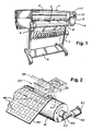
- the invention is amenable to implementation in a great variety of products. It can be embodied in a printer/plotter that includes a main case 1 (Fig. 1) with a window 2, and a left-hand pod 3 which encloses one end of the chassis. Within that enclosure are carriage-support and -drive mechanics and one end of the printing-medium advance mechanism, as well as a pen-refill station with supplemental ink cartridges.
- the printer/plotter also includes a printing-medium roll cover 4, and a receiving bin 5 for lengths or sheets of printing medium on which images have been formed, and which have been ejected from the machine.
- a bottom brace and storage shelf 6 spans the legs which support the two ends of the case 1.
- an entry slot 7 for receipt of continuous lengths of printing medium 4. Also included are a lever 8 for control of the gripping of the print medium by the machine.
- a front-panel display 11 and controls 12 are mounted in the skin of the right-hand pod 13. That pod encloses the right end of the carriage mechanics and of the medium advance mechanism, and also a printhead cleaning station. Near the bottom of the right-hand pod for readiest access is a standby switch 14.
- a cylindrical platen 41 (Fig. 2) ⁇ driven by a motor 42, worm 43 and worm gear 44 under control of signals from a digital electronic processor ⁇ rotates to drive sheets or lengths of printing medium 4A in a medium-advance direction. Print medium 4A is thereby drawn out of the print-medium roll cover 4.
- a pen-holding carriage assembly 20 carries pens back and forth across the printing medium, along a scanning track ⁇ perpendicular to the medium-advance direction ⁇ while the pens eject ink.
- the medium 4A thus receives inkdrops for formation of a desired image, and is ejected into the print-medium bin 5.
- the image may be a test pattern of numerous color patches or swatches 56, for reading by an optical sensor to generate calibration data.
- test patterns are for use in monitoring for and detecting printing elements (e. g. nozzles) that are performing poorly or not at all.
- a small automatic optoelectronic sensor 51 rides with the pens on the carriage and is directed downward to obtain data about pen condition (nozzle firing volume and direction, and interpen alignment).
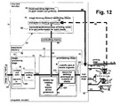
- the sensor 51 can readily perform optical measurements 65, 81, 82 (Fig. 12); suitable algorithmic control 82 is well within the skill of the art, and may be guided by the discussions in the present document.
- a very finely graduated encoder strip 36 is extended taut along the scanning path of the carriage assembly 20 and read by another, very small automatic optoelectronic sensor 37 to provide position and speed information 37B for the microprocessor.
- One advantageous location for the encoder strip 36 is immediately behind the pens.
- a currently preferred position for the encoder strip 33 (Fig. 3), however, is near the rear of the pen-carriage tray ⁇ remote from the space into which a user's hands are inserted for servicing of the pen refill cartridges.
- the sensor 37 is disposed with its optical beam passing through orifices or transparent portions of a scale formed in the strip.
- the pen-carriage assembly 20 is driven in reciprocation by a motor 31 ⁇ along dual support and guide rails 32, 34 ⁇ through the intermediary of a drive belt 35.
- the motor 31 is under the control of signals from the digital processor.
- the pen-carriage assembly includes a forward bay structure 22 for pens ⁇ preferably at least four pens 23-26 holding ink of four different colors respectively. Most typically the inks are yellow in the leftmost pen 23, then cyan 24, magenta 25 and black 26.
- Another increasingly common system has inks of different colors that are actually different dilutions for one or more common chromatic colors, in the several pens.
- different dilutions of black may be in the several pens 23-26.
- both plural-chromatic-color and plural-black pens may be in a single printer, either in a common carriage or plural carriages.
- a rear tray 21 carrying various electronics.
- the colorimeter carriage too has a rear tray or extension 53 (Fig. 3), with a step 54 to clear the drive cables 35.
- Figs. 1 through 3 most specifically represent a system such as the Hewlett Packard printer/plotter model "DesignJet 2000CP", which does not include the present invention. These drawings, however, also illustrate certain embodiments of the invention, and ⁇ with certain detailed differences mentioned below ⁇ a printer/plotter that includes preferred embodiments of the invention.
- This printmask modification method maintains the global quality of the original printmask, and achieves a good local quality in locations where the defective nozzle was replaced. It requires practically no additional computations, and the excessive load caused by the defective nozzle is uniformly distributed over a set of replacement nozzles.
- This invention concerns a fourth method, different from handmade masks, mask redesign or "backup nozzle” ⁇ Backup Matrix which does not compromise the original quality at those lines where the damaged nozzle was not employed, while at lines affected by the damaged nozzle it achieves suboptimal printmask quality.
- every nozzle has a location dependent backup. This way, when all the nozzles in a printmask line are operational the original printmask pattern is maintained.
- the printmask pattern is modified, though only in defective nozzle locations.
- the replacement nozzle in those locations is chosen so as to be optimal with respect to the fixed surrounding pattern and the printmask requirements.
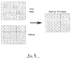
- the pass number corresponding to the inverse mapping is replaced by the pass-number entry of the same location in the backup matrix. For example, suppose the printmask and the corresponding backup matrix are as in Fig. 5 and a defective nozzle has been detected, whose inverse mapping is shown below. Line 1 2 3 4 5 6 Pass - 6 - 4 - 3
- the matrix form of the backup-matrix method is especially effective and natural in the printmask design process, during which printmask entries are iteratively optimized. Entries are modified in turn as follows.
- Printmask entries are approached in either an ordered, random, or adaptively determined sequence.
- the pass numbers are ordered according to their fit to the printmask requirements and the printmask entry is modified to contain the best fit. This order may be induced by either deterministic or random functions.
- backup-matrix entries should contain the best alternatives to the printmask entries, the backup matrix could be designed simultaneously with the printmask, so that in each iteration backup matrix entries contain second best options. See Fig. 6 for a flow chart describing this design method.
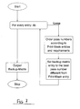
- the backup matrix could be filled sequentially, with best alternatives after the printmask has been optimized. See Fig. 7 for a flow chart describing this design method.
- Additional implementation options include the following.
- This more-advanced form of the invention never forbids using a nozzle ⁇ unless required by physical (electronic) limitations on frequency of use. Apart from this usage-frequency restriction, i. e. as long as it is nozzle weighting for printmask purposes that is under consideration, this form of thee invention at most lowers a nozzle to the bottom of a priority list. Nevertheless, the bad nozzle always has the chance to print. Preferably there is never any exception to the algorithm, and it will actually print if one or a combination of the following conditions requires it.
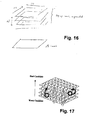
- the precooked mask is a three-dimensional matrix (Fig. 8).
- Fig. 8 One might think of it as a stack of matrices. It is better thought of as a matrix of stacks. That is, for every single location on the paper, a full range of candidates is offered.
- This precooked mask may either be generated on the fly for each plot, be generated at printer's initialization or kept in a hard disk all the time. When the printer needs to print, the precooked mask is retrieved or generated, and then the reheating process begins.
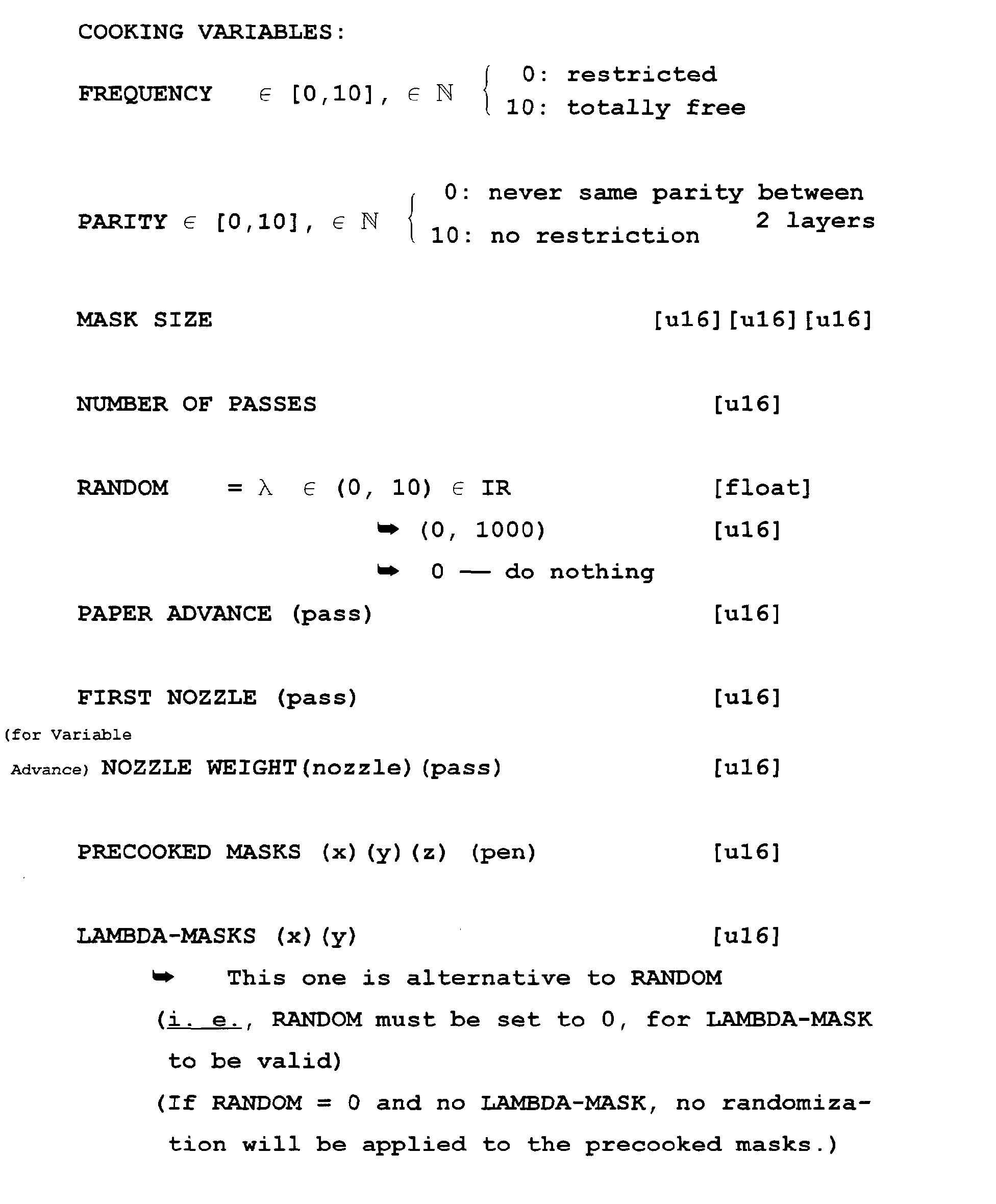
- the reheating process basically consists of picking, for each print level, a candidate from the list. Although, by default, the first-level mask will pick the best candidate, the second-level mask will pick the second best candidate and so on, things are not that obvious when Nozzle Weighting enters into the game.
- the best possible candidate is picked with a probability that is proportional to the nozzle weight. That is, if nozzle weight is 1000, the best candidate is picked for level 1 with a probability of 100%. If the next candidate nozzle is also weighted with a 1000, it will be picked for the mask that corresponds to level 2 and so on.
- this nozzle will be picked in 60% of the cases. In the remaining 40% of the cases, the next candidate in the list will be evaluated for that position, and the rejected nozzle is moved to the lowest rank of the list, just in case it can help filling up higher levels of the mask.
- the new candidate that is evaluated may again be picked or rejected, depending on its weight.
- the necessary precautions have been included in the algorithm to prevent rejection of all the candidates.
- the described probabilistic process is repeated for each layer that is to be filled up.
- Nozzles rejected by the second, third layers and so on will also be moved to the bottom of the priority list. This means that the first rejected nozzle is no longer at the bottom of the list, and could therefore be selected.
- Another criterion also takes part in the reheating process ⁇ namely, depending on the carriage velocity that is chosen for the printmode, it may be decided that a single nozzle cannot shoot on two adjacent locations. This means that, when printing at sufficiently fast carriage speeds, if nozzle 1 has been selected to fire in position X, for layer 2, the same nozzle will not be allowed to fire in position X + 1, for any mask level.
- This nozzle will not be dropped to the bottom of the priority list; it will just be taken out of the list, because this is the only way to ensure that a nozzle is not fired. Notice that this absolute rejection only occurs based on firing-frequency restrictions, so that nozzle 1 can fire again in position X + 2.
- the first step is computationally expensive, but common for all the printheads in a printer. It can be generated either inside or outside the printer, and it provides the texture of the mask as well as all the possible combinations ( N rows ⁇ columns combinations, for the first level only).
- the second step is printhead-dependent, but much cheaper in terms of computational effort, and it can even be executed before every single printout. It provides the nozzle management functionality, computed cell by cell through the use of randomization features. Thus precooked-mask features enable modulation of nozzle usage differently for every single row (potentially every single location) in the mask and for arbitrary print-medium advance.
- the initial precooking stage advantageously generic and invariant, is preferably followed by a cell-by-cell algorithm that adapts dynamically to printhead conditions, and other conditions ⁇ and can be executed very often and very quickly.
- the present disclosure offers a new method to have better control of precooked mask generation.
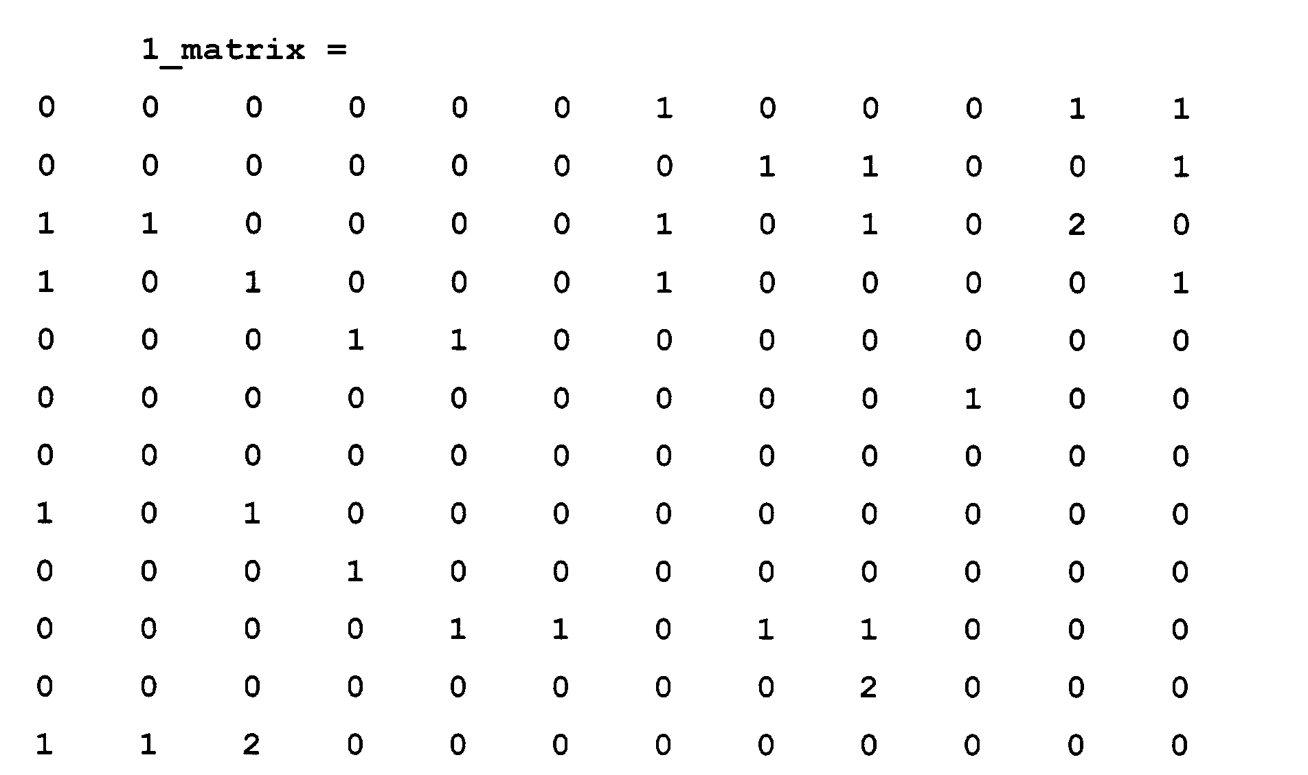
- precooked masks were invented. They are successful in recalculating nozzle weighting in a very short time, but it looks like it is still harder to generate a precooked mask out of a syntactical statement.
- a main objective of this invention is to have better control of precooked mask design.
- handmade precooked masks are to be fed into the same reheating process as was used for larger precooked masks, a process is needed that substantially enlarges handmade precooked masks.
- An analogy is popcorn in the microwave oven; this is how handmade precooked masks are transformed by the Popup process!
- the purpose of this invention is to improve the method by which printmasks are generated.
- the pen-carriage assembly is represented separately at 20 (Fig. 12) when traveling to the left 16 while discharging ink 18, and at 20' when traveling to the right 17 while discharging ink 19. It will be understood that both 20 and 20' represent the same pen carriage.
- the previously mentioned digital processor 71 provides control signals 20B to fire the pens with correct timing, coordinated with platen drive control signals 42A to the platen motor 42, and carriage drive control signals 31A to the carriage drive motor 31.
- the processor 71 develops these carriage drive signals 31A based partly upon information about the carriage speed and position derived from the encoder signals 37B provided by the encoder 37.
- the codestrip 33 thus enables formation of color inkdrops at ultrahigh precision during scanning of the carriage assembly 20 in each direction ⁇ i. e., either left to right (forward 20') or right to left (back 20).
- New image data 70 are received 191 into an image-processing stage 73, which may conventionally include a contrast and color adjustment or correction module 76 and a rendition, scaling etc. module 77.
- a printmasking module 74 typically including a stage 61 for specific pass and nozzle assignments.
- the latter stage 61 performs generally conventional functions, but in accordance with certain aspects of the present invention also particularly includes means 171 for defining or creating the printmask as a matrix of stacks.
- the matrix structure established in the creating means 171 is conditioned or configured 187 by the rotating means 84, as indicated in the earlier "Summary of the Disclosure" part of this document, and further in sections 3 and 4 above.
- Information for driving the rotating means 84 is derived by a module 63 that controls 80 the final output stage 78 to print nozzle test patterns for reading by the sensor 51, Fig. 12 (or if preferred to eject inkdrops selectively into an optical detector, not shown, that senses the drops directly, e. g. while in flight).
- the resulting sensor signal 65 is monitored in a monitoring module 72.
- That module operates according to a program 81 for reading the sensor signal, and another program stage 82 that measures the signals, and compares some signals with others, to determine inking levels and thereby determine the performance for each band of the printheads.
- the results of these measurements are massaged in a control stage 83, deriving an operating signal 68 for the previously introduced rotating means 84.
- the means represented by the several operational blocks 63, 72, 83, 61, 84 of the present invention ⁇ as well as the conventional modules 73, 74, 74, 78, and also the swath-characteristic-varying functions 171, 176, 181 as shown ⁇ are implemented within integrated circuits 71. Given the statements of function and the swath diagrams presented in this document, an experienced programmer of ordinary skill in this field can prepare suitable programs for operation of the circuits.
- the integrated circuits 71 may be part of the printer itself, as for example an application-specific integrated circuit (ASIC), or may be program data in a read-only memory (ROM) ⁇ or during operation may be parts of a programmed configuration of operating modules in the central processing unit (CPU) of a general-purpose computer that reads instructions from a hard drive.
- ASIC application-specific integrated circuit
- ROM read-only memory
- CPU central processing unit
- RIP raster image processor
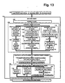
- the system first retrieves 101 (Fig. 13) its operating program appropriately ⁇ i. e. , by reading instructions from memory in case of a firmware or software implementation, or by simply operating dedicated hardware in case of an ASIC or like implementation. Once prepared or initialized in this way, the method proceeds to generation 102 of a printmask.
- mask establishment 103 matrix-structure establishment 100
- nonfunctionality determination 115 nonfunctionality determination 115
- replacement 118 of individual values with backups from the matrix ⁇ in accordance with the particular preparations made in the earlier stages 103, 100, 115.
- three separate parallel vertical columns of processes appear.
Landscapes
- Engineering & Computer Science (AREA)
- Multimedia (AREA)
- Signal Processing (AREA)
- Physics & Mathematics (AREA)
- Mathematical Physics (AREA)
- General Engineering & Computer Science (AREA)
- General Physics & Mathematics (AREA)
- Theoretical Computer Science (AREA)
- Ink Jet (AREA)
- Printing Methods (AREA)
Abstract
Description
| | 1 | 2 | 3 | 4 | 5 | 6 |
| Pass | - | 6 | - | 4 | - | 3 |
- More than one backup matrix may be used. A series of (e. g. two) backup matrices could be used so that if the backup nozzle assigned for a defective nozzle is also out of order, a second backup (stored in the second backup matrix) would be available.
- The printmask design requirement in the second backup- matrix design method may be augmented with backup-specific design rules. For example the pattern of the backup matrix in Fig. 2 would be considered bad in a printmask; as back-ups all the entries fit well into the printmask, but in case two nozzles assigned to nearby printmask locations are to be replaced, it could cause severe printing artifacts. To prevent such problems, additional requirements, on the pattern of the resulting backup matrix, should be added.
- All the needed drops per cell_600 must be addressed.
- There are only N passes in which to do so.
- The frequency restrictions on the pen are stronger than any Nozzle Weighting criterion. In fact, these are the top-priority restrictions, and nozzles affected by them will not just fall to the bottom of the priority list, they will actually be discarded from the list.
- Variable Paper-Advance Printmodes (compatible with multilevel printing) as introduced by Zapata; and
- Pass-Dependent Nozzle Weighting: Variable Paper Advance Printmodes have new drawbacks that can be made up for with this new technique (nozzle usage is specified for every single pass).
- The step advance sequence (this is how Variable-Advance Printmodes can be supported).
- The number of the pass being fired at (this is how Pass-Dependent Nozzle Weighting can be supported).
- In general, any other factor could influence the weight of a certain nozzle, when firing at a certain pass.
- The combination of N nozzles that print on a single row (N being the number of passes) can be unique for the whole mask, thanks to use of variable paper advance. Earlier, by comparison, a combination of N nozzles was repeated N times across the mask.
- Error hiding need not be used any longer. Instead preferably each nozzle is given a printing probability in the range from zero to one hundred percent of its nominal usage. This new concept, nozzle weighting, is advantageously varied from swath to swath to provide pass-dependent nozzle weighting.
- When a nozzle prints below its nominal usage, other nozzles make up for the difference. These other nozzles are not exactly backup nozzles, because they can also compensate for only a part of the work of a below-nominal nozzle. Earlier, what was replaced by one or a plurality of backup nozzles was the entire function of the original nozzle.
- When a nozzle prints below its nominal usage, up to N · (N - 1) nozzles can compensate for it, thanks to the variable advance. Earlier, only N - 1 nozzles could participate in compensation.
- All these forms of nozzle management can be realized for multilevel printing ― i. e. for different numbers of drops projected into the same cell. Earlier, only binary printing was demonstrated.
- A mask for supporting all these features can be generated in two completely independent steps.
- Better control of printmask design.
- Gradual transition from regular to fuzzy masks.
- Nozzle weighting does not make masks fuzzier.
- Less memory required ― a mask may fit in the cache.
- Export to other artisans.

Claims (21)
- A printmasking method for use in incremental printing; said method comprising the steps of:establishing a printmask;determining when an individual value in the printmask is nonfunctional; andfollowing a preprogrammed procedure to accommodate the nonfunctional individual value.
- The method of claim 1:further comprising the step of establishing a matrix of corresponding backup entries for values in the printmask; andwherein the preprogrammed procedure comprises individually replacing exclusively the individual determined nonfunctional value with exclusively a corresponding individual backup entry from the matrix.
- The method of claim 2, particularly for use with multiple printing elements, each printing element being used in multiple locations of the printmask; and wherein:
the matrix of backup entries provides a location-dependent backup for substantially each printing element. - The method of claim 2, further comprising the steps of:establishing a second backup matrix of further backup entries;determining when an individual value in the first-mentioned matrix is nonfunctional; andindividually replacing exclusively the individual determined nonfunctional value of the first-mentioned matrix with exclusively a corresponding individual backup entry from the second backup matrix.
- The printmasking method of claim 1:
wherein the printmask-establishing step comprises establishing a printmask in the form of a matrix of stacks of corresponding entries for positions in the printmask; and further comprising the steps of:individually selecting an entry for substantially each position in the printmask, respectively, by choosing an individual entry from the corresponding stack in the matrix; andprinting an image using the respective individually selected entry at substantially each position in the printmask. - The printmasking method of claim 1, wherein:the printmask-establishing step comprises establishing a matrix of stacks of corresponding backup entries for values in the printmask; andthe preprogrammed procedure comprises individually replacing exclusively the individual determined nonfunctional value with exclusively a corresponding individual backup entry from a corresponding stack in the matrix.
- The method of either claim 5 or 6, wherein:
the replacing step comprises rotating entries in the stack for selection. - The method of either claim 5 or 6, for use with multiple individual printing elements; wherein the replacing step comprises:associating a respective individual printing element with each entry in the stack; andidentifying with the associated printing element a respective numerical weight; andapplying to each entry in the stack a selection probability related to the identified numerical weight.
- The method of claim 8, wherein:any element initially rejected by virtue of the applied selection probability is shifted to the bottom of the stack in rotation;whereby it is possible for an initially rejected element to later rotate to the top of a stack for reconsideration.
- The method of claim 9, further comprising:assigning to the determined nonfunctional element a relatively low numerical weight; andapplying to a corresponding value in a printmask stack a relatively low selection probability.
- The method of either claim 5 or 6, further comprising:
modifying the printmask to reflect firing-frequency limitations which carry a higher authority level than the numerical weights. - The method of claim 11, wherein:
whenever the printer is to print, the mask is generated or retrieved for use and then, before use, is processed by stack rotation at substantially each position. - The printmasking method of claim 1 wherein:the printmask-establishing step comprises:establishing a seminal printmask,tiling the established seminal printmask, to create a larger printmask having closely related properties, andforming a less-regular printmask by injecting noise into the larger printmask to disrupt regularity arising in the tiling step; andfurther comprising the step of using the less-regular printmask in incremental printing of an image.
- The method of claim 13, wherein:the using step comprises printing in a particular number of passes over some portion of the image; andthe establishing step comprises preparation of a mask that is approximately cubical, each side thereof being a number of pixels or layers approximately equal to the particular number of passes.
- The method of claim 14, wherein:said mask preparation comprises forming a matrix of stacks of possible choices of pass number, each of said choices having an associated desired probability of use;the using step comprises probabilistically evaluating each choice at a top of a stack, each choice being subject to rejection through said evaluating; andthe using step further comprises, if a choice in a certain stack is rejected, rotating the certain stack in a particular direction to bring a different choice to the top of the certain stack.
- The method of claim 13, wherein the noise-injecting step comprises:
rotating selected stacks in the larger printmask. - The method of claim 16, wherein:
rotation of a certain stack in said particular direction, starting from the position of the certain stack in the seminal printmask, tends to reduce randomness. - The method of claim 13, for use with plural printheads; and wherein:the establishing step comprises defining a respective seminal printmask for each of the plural printheads;the tiling step comprises tiling each respective seminal printmask to make a respective larger printmask for each of the plural printheads; andthe noise-injecting step comprises inserting noise into each said respective larger printmask.
- The method of claim 18, wherein the noise-inserting comprises:
inserting substantially identical noise into each said respective larger printmask. - The method of claim 18, wherein the respective-printmask defining comprises:replicating a single seminal printmask to form a respective seminal printmask for each of the plural printheads; andmodifying each respective seminal printmask to accommodate respective requirements of its printhead.
- Apparatus for use in incremental printing of an image; said apparatus comprising:means defining a printmask in the form of a matrix of stacks of corresponding entries for positions in the printmask;means for rotating each stack if desired to individually select an entry for substantially each position in the printmask, respectively; andmeans for printing the image using selected entries.
Priority Applications (1)
| Application Number | Priority Date | Filing Date | Title |
|---|---|---|---|
| JP2001054964A JP2001277495A (en) | 2000-02-29 | 2001-02-28 | Method for processing print mask |
Applications Claiming Priority (2)
| Application Number | Priority Date | Filing Date | Title |
|---|---|---|---|
| US21931500P | 2000-02-29 | 2000-02-29 | |
| US219315P | 2000-02-29 |
Publications (3)
| Publication Number | Publication Date |
|---|---|
| EP1130539A2 true EP1130539A2 (en) | 2001-09-05 |
| EP1130539A3 EP1130539A3 (en) | 2002-09-25 |
| EP1130539B1 EP1130539B1 (en) | 2006-06-14 |
Family
ID=22818779
Family Applications (1)
| Application Number | Title | Priority Date | Filing Date |
|---|---|---|---|
| EP00117780A Expired - Lifetime EP1130539B1 (en) | 2000-02-29 | 2000-08-18 | Improvements in automated and semiautomated printmask generation for incremental printing |
Country Status (3)
| Country | Link |
|---|---|
| US (1) | US6443556B1 (en) |
| EP (1) | EP1130539B1 (en) |
| DE (1) | DE60028723T2 (en) |
Cited By (1)
| Publication number | Priority date | Publication date | Assignee | Title |
|---|---|---|---|---|
| EP1297964A1 (en) * | 2001-09-29 | 2003-04-02 | Hewlett-Packard Company | A system and method for producing print masks to eliminate step advance and swath height error banding |
Families Citing this family (11)
| Publication number | Priority date | Publication date | Assignee | Title |
|---|---|---|---|---|
| US7027185B2 (en) * | 2001-07-30 | 2006-04-11 | Hewlett-Packard Development Company, L.P. | Linearization of an incremental printer by measurements referred to a media-independent sensor calibration |
| JP4343867B2 (en) * | 2004-04-13 | 2009-10-14 | キヤノン株式会社 | Inkjet recording device |
| US7287824B2 (en) | 2004-07-16 | 2007-10-30 | Hewlett-Packard Development Company, L.P. | Method and apparatus for assessing nozzle health |
| JP4669249B2 (en) * | 2004-08-30 | 2011-04-13 | キヤノン株式会社 | Inkjet recording method, inkjet recording system, and inkjet recording apparatus |
| JP4126384B2 (en) * | 2004-09-17 | 2008-07-30 | 富士フイルム株式会社 | Image recording apparatus and image correction method |
| US20060061610A1 (en) * | 2004-09-17 | 2006-03-23 | Fuji Photo Film Co., Ltd. | Image forming apparatus |
| US7207640B2 (en) | 2004-11-20 | 2007-04-24 | Hewlett-Packard Development Company, L.P. | Progressive and fast printmask revision based on incremental changes to printing element condition |
| US20090027696A1 (en) * | 2007-07-24 | 2009-01-29 | Quintana Jason M | Printmode architecture |
| US8125687B2 (en) * | 2008-10-06 | 2012-02-28 | Canon Kabushiki Kaisha | Target for color characterization of color printer |
| CN107079076B (en) * | 2014-10-31 | 2019-11-12 | 惠普发展公司,有限责任合伙企业 | Post-process halftone images |
| US11451371B2 (en) * | 2019-10-30 | 2022-09-20 | Dell Products L.P. | Data masking framework for information processing system |
Family Cites Families (11)
| Publication number | Priority date | Publication date | Assignee | Title |
|---|---|---|---|---|
| US5992962A (en) * | 1994-12-22 | 1999-11-30 | Hewlett-Packard Company | Print masks for inkjet printers |
| EP0730248A1 (en) * | 1995-03-01 | 1996-09-04 | Hewlett-Packard Company | Method and system for interlaced printing |
| US5920682A (en) * | 1996-09-20 | 1999-07-06 | Seiko Epson Corporation | Multiple layer cluster dither matrix for reducing artifacts in printed images |
| US6067405A (en) * | 1997-03-04 | 2000-05-23 | Hewlett-Packard Company | Multipass color printmasks based on location rules to minimize hue shift, banding and coalescence |
| US6283572B1 (en) * | 1997-03-04 | 2001-09-04 | Hewlett-Packard Company | Dynamic multi-pass print mode corrections to compensate for malfunctioning inkjet nozzles |
| CA2298530A1 (en) * | 1997-08-01 | 1999-02-25 | David Neese | Ink-jet printer, method and system compensating for nonfunctional print elements |
| US6157461A (en) * | 1997-10-27 | 2000-12-05 | Hewlett-Packard Company | Method of generating randomized masks to improve image quality on a printing medium |
| US6185002B1 (en) * | 1998-03-16 | 2001-02-06 | Hewlett-Packard Company | Reduction of periodic artifacts in incremental printing, through use of asymmetric randomized superpixels |
| US20020008723A1 (en) * | 1998-07-21 | 2002-01-24 | Xin Wen | Printer and method of compensating for malperforming and inoperative ink nozzles in a print head |
| US6441922B1 (en) * | 1998-10-31 | 2002-08-27 | Hewlett-Packard Company | Reduction of banding in incremental printing, through selection among colorimetric equivalents |
| DE69908289T2 (en) * | 1999-02-19 | 2004-04-08 | Hewlett-Packard Co. (N.D.Ges.D.Staates Delaware), Palo Alto | Printing process for automatically compensating for faulty inkjet nozzles |
-
2000
- 2000-08-02 US US09/632,197 patent/US6443556B1/en not_active Expired - Fee Related
- 2000-08-18 EP EP00117780A patent/EP1130539B1/en not_active Expired - Lifetime
- 2000-08-18 DE DE60028723T patent/DE60028723T2/en not_active Expired - Lifetime
Cited By (1)
| Publication number | Priority date | Publication date | Assignee | Title |
|---|---|---|---|---|
| EP1297964A1 (en) * | 2001-09-29 | 2003-04-02 | Hewlett-Packard Company | A system and method for producing print masks to eliminate step advance and swath height error banding |
Also Published As
| Publication number | Publication date |
|---|---|
| EP1130539B1 (en) | 2006-06-14 |
| DE60028723D1 (en) | 2006-07-27 |
| DE60028723T2 (en) | 2007-02-08 |
| EP1130539A3 (en) | 2002-09-25 |
| US6443556B1 (en) | 2002-09-03 |
Similar Documents
| Publication | Publication Date | Title |
|---|---|---|
| US6454392B1 (en) | Adaptive depletion masks for improving print quality | |
| EP0990528B1 (en) | Fast building of masks for use in incremental printing | |
| EP1130539B1 (en) | Improvements in automated and semiautomated printmask generation for incremental printing | |
| JPH10250114A (en) | Printing apparatus for plural-gradation level | |
| US7265770B2 (en) | Method of camouflaging defective print elements in a printer | |
| US6788432B1 (en) | Optimal-size and nozzle-modulated printmasks for use in incremental printing | |
| EP1398157A1 (en) | Removal or mitigation of artifacts in incremental printing | |
| US7715043B2 (en) | Multilevel print masking method | |
| US6965452B2 (en) | Masks on demand for use in incremental printing | |
| JPH08252930A (en) | Printing method | |
| JP5086705B2 (en) | Image processing apparatus and method | |
| US7046389B2 (en) | Variable density under/overprinting maps for improving print quality | |
| EP0944024B1 (en) | Reduction of periodic artifacts in incremental printing | |
| US6854828B2 (en) | Removal or mitigation of artifacts in composite-color incremental printing | |
| EP1182867A2 (en) | Use of superpixels to enhance image quality in printing devices | |
| US6749280B2 (en) | Recording apparatus, recording method therefor and program therefor | |
| EP1658979B1 (en) | Printmask revision based on incremental changes to printing element condition | |
| EP4420882B1 (en) | Automatic tuning compensation mechanism | |
| JPH1178060A (en) | Apparatus and method for forming image | |
| US6739772B2 (en) | Printing method and apparatus | |
| JP2001277495A (en) | Method for processing print mask | |
| US20250313024A1 (en) | Defective inkjet compensation using halftone screen permutations | |
| EP1536371B1 (en) | Method of camouflaging defects of printing elements in a printer | |
| US6851793B2 (en) | Very cost-effective incremental printing method and apparatus to directly reduce bidirectional hue shift | |
| JP2010069802A (en) | Image formation device and method for controlling the same |
Legal Events
| Date | Code | Title | Description |
|---|---|---|---|
| PUAI | Public reference made under article 153(3) epc to a published international application that has entered the european phase |
Free format text: ORIGINAL CODE: 0009012 |
|
| AK | Designated contracting states |
Kind code of ref document: A2 Designated state(s): AT BE CH CY DE DK ES FI FR GB GR IE IT LI LU MC NL PT SE |
|
| AX | Request for extension of the european patent |
Free format text: AL;LT;LV;MK;RO;SI |
|
| RIC1 | Information provided on ipc code assigned before grant |
Free format text: 7G 06K 15/10 A, 7B 41J 2/165 B |
|
| PUAL | Search report despatched |
Free format text: ORIGINAL CODE: 0009013 |
|
| AK | Designated contracting states |
Kind code of ref document: A3 Designated state(s): AT BE CH CY DE DK ES FI FR GB GR IE IT LI LU MC NL PT SE |
|
| AX | Request for extension of the european patent |
Free format text: AL;LT;LV;MK;RO;SI |
|
| 17P | Request for examination filed |
Effective date: 20030320 |
|
| AKX | Designation fees paid |
Designated state(s): DE FR GB IT |
|
| 17Q | First examination report despatched |
Effective date: 20050221 |
|
| GRAP | Despatch of communication of intention to grant a patent |
Free format text: ORIGINAL CODE: EPIDOSNIGR1 |
|
| GRAS | Grant fee paid |
Free format text: ORIGINAL CODE: EPIDOSNIGR3 |
|
| GRAA | (expected) grant |
Free format text: ORIGINAL CODE: 0009210 |
|
| RIN1 | Information on inventor provided before grant (corrected) |
Inventor name: ZAPATA, ELIZABETH Inventor name: GRACIA, JOAN MANUEL Inventor name: BAHARAV, IZHAK Inventor name: GARCIA, SANTIAGO Inventor name: MIQUEL, ANTONI GIL Inventor name: SHAKED, DORON |
|
| AK | Designated contracting states |
Kind code of ref document: B1 Designated state(s): DE FR GB IT |
|
| PG25 | Lapsed in a contracting state [announced via postgrant information from national office to epo] |
Ref country code: IT Free format text: LAPSE BECAUSE OF FAILURE TO SUBMIT A TRANSLATION OF THE DESCRIPTION OR TO PAY THE FEE WITHIN THE PRESCRIBED TIME-LIMIT;WARNING: LAPSES OF ITALIAN PATENTS WITH EFFECTIVE DATE BEFORE 2007 MAY HAVE OCCURRED AT ANY TIME BEFORE 2007. THE CORRECT EFFECTIVE DATE MAY BE DIFFERENT FROM THE ONE RECORDED. Effective date: 20060614 |
|
| REG | Reference to a national code |
Ref country code: GB Ref legal event code: FG4D |
|
| REF | Corresponds to: |
Ref document number: 60028723 Country of ref document: DE Date of ref document: 20060727 Kind code of ref document: P |
|
| PLBE | No opposition filed within time limit |
Free format text: ORIGINAL CODE: 0009261 |
|
| STAA | Information on the status of an ep patent application or granted ep patent |
Free format text: STATUS: NO OPPOSITION FILED WITHIN TIME LIMIT |
|
| EN | Fr: translation not filed | ||
| 26N | No opposition filed |
Effective date: 20070315 |
|
| PG25 | Lapsed in a contracting state [announced via postgrant information from national office to epo] |
Ref country code: FR Free format text: LAPSE BECAUSE OF FAILURE TO SUBMIT A TRANSLATION OF THE DESCRIPTION OR TO PAY THE FEE WITHIN THE PRESCRIBED TIME-LIMIT Effective date: 20070309 |
|
| PG25 | Lapsed in a contracting state [announced via postgrant information from national office to epo] |
Ref country code: FR Free format text: LAPSE BECAUSE OF FAILURE TO SUBMIT A TRANSLATION OF THE DESCRIPTION OR TO PAY THE FEE WITHIN THE PRESCRIBED TIME-LIMIT Effective date: 20060614 |
|
| REG | Reference to a national code |
Ref country code: GB Ref legal event code: 732E Free format text: REGISTERED BETWEEN 20120329 AND 20120404 |
|
| PGFP | Annual fee paid to national office [announced via postgrant information from national office to epo] |
Ref country code: GB Payment date: 20120828 Year of fee payment: 13 |
|
| PGFP | Annual fee paid to national office [announced via postgrant information from national office to epo] |
Ref country code: DE Payment date: 20120829 Year of fee payment: 13 |
|
| GBPC | Gb: european patent ceased through non-payment of renewal fee |
Effective date: 20130818 |
|
| PG25 | Lapsed in a contracting state [announced via postgrant information from national office to epo] |
Ref country code: DE Free format text: LAPSE BECAUSE OF NON-PAYMENT OF DUE FEES Effective date: 20140301 |
|
| REG | Reference to a national code |
Ref country code: DE Ref legal event code: R119 Ref document number: 60028723 Country of ref document: DE Effective date: 20140301 |
|
| PG25 | Lapsed in a contracting state [announced via postgrant information from national office to epo] |
Ref country code: GB Free format text: LAPSE BECAUSE OF NON-PAYMENT OF DUE FEES Effective date: 20130818 |