BACKGROUND OF THE INVENTION
Field of the Invention
-
The present invention relates to runtime environment
component services, and in particular to a runtime
environment component services provided by a first
computer system to a second computer system over a
communication network.
Description of Related Art
-
Today, many computer networks are arranged as client-server
systems. In a client-server system, a
potentially large number of smaller computer systems,
like laptops or handhold organizers, called clients,
are, temporarily or permanently connected to a larger
computer system, called server. The connection between
the clients and the server may be effected, for example,
via the Internet.
-
In client-server systems, a client typically has limited
storage and processing capabilities. Nevertheless, many
software programs are executed on the clients. One
prior art way to make a software program on the server
available to clients was to use a browser on the client.
The browser was used to transfer a relatively large
software program or a relatively large part thereof from
the server to a client so that the software program
could be executed locally on the client. This method
required that the software program or a part thereof be
stored and processed on the client.
-
For this purpose, the client must have sufficient
storage capacity and processing capability to execute
the software program locally. These requirements may
conflict with the aim of having smaller and smaller
clients, including cellular telephones, which may not
have enough storage capacity or processing capability
for storing or processing, respectively, large software
programs or large parts of software programs.
-
Frequently, a software program requested by a client for
execution is transferred every time the software program
is executed. The speed of this download depends on the
available data transfer capacity of the network
connecting the server and the client. Here, frequently
the available bandwidth of the network connection is
decisive. In many instances the described client-server
systems would be undesirably slow in executing a
software program, because the download takes too much
time.
-
Therefore, software programs, which are called
frequently for execution on a client, may be
permanently, or at least for some time, stored on the
client. This leads, however, to the task of regularly,
and maybe even individually, updating a potentially
large number of clients, if relevant software programs
are amended or updated. Considerable administration
efforts for client-server systems may be the
consequence.
-
It is also known to include into a software program
executed on a client procedures, which are executed on a
server. A prior technique to implement this used CORBA.
For example, certain more complicated calculations, the
result of which may be needed on a client, were carried
out on a server connected with the client over a
network. However, this required that the program
developer include particular commands into the code of
the software program to be executed on the client for
calling the software program to be executed on the
server, in the given example the calculation program.
This was not only cumbersome, but also led to
incompatibilities when the software program to be
executed on the server was amended.
-
It is further known to allow a user to initiate
execution of a program server from a client and to
review the results of the program execution on the
client. This approach is used in the UNIX X-Windows
system. However, this approach did not permit the
client to control the program and did not permit
integration of server side functionality into the client
side environment at the level of function calls.
SUMMARY OF THE INVENTION
-
It is an object of the present invention to provide
improved access from a first computer system to
resources available at a second computer system.
-
The object of the invention is achieved by the features
of the independent claims.
-
According to one embodiment of the present invention, a
user device, a first computer system, includes a
lightweight component that receives user input actions
for a runtime environment component that is executing on
a second computer system. The lightweight component
sends a remote input action command to a user interface
infrastructure that is executing on the second computer
system.
-
In response to the remote input action command, the user
interface infrastructure sends a local input action
command to the runtime environment component that
processes the command, and issues a local output command
to the user interface infrastructure that in turn sends
a remote output command to the lightweight component on
the user device. In response to the remote output
command, the lightweight component causes an output on
the user device. This output could be redrawing a
display, playing a sound, or perhaps routing information
to a local printer.
-
All the management of components in the user interface,
management of data and so on is performed on the second
computer system and so the lightweight component only
has, for example, to update the display to reflect the
state of the runtime environment component as indicated
by the remote output command received. It appears to
the user that the runtime environment component is
executing locally on the user device despite that fact
that the user device is only functioning as an
input/output device for the runtime environment
component.
-
In one embodiment, a method for presenting a runtime
environment component service by a first computer system
to a second computer system over a communication network
is performed by the first computer system. The method
includes generating a user interface infrastructure on
the first computer system. The user interface
infrastructure receives graphic user interface events
from the second computer system and sends remote graphic
user interface commands to the second computer system.
The user interface infrastructure is used to initialize
the runtime environment component service. The runtime
environment component service sends graphic user
interface commands to the user interface infrastructure.
-
In another embodiment, the first computer system
receives a remote input action command for a runtime
environment component service via a communication
network. The remote input action is being generated in
the second computer system by a lightweight component
corresponding to the runtime environment component
service. A local input action command is transmitted to
the runtime environment component service in response to
the remote input action command. The local input action
command is processed by the runtime environment
component service, and a local output command is
generated by the runtime environment component service
for a graphical user interface. A remote output command
is transmitted to the lightweight component in response
to the local output command.
-
In yet another embodiment, a method for enabling a user
device to run a runtime environment component on another
computer includes running a browser on the user device.
A lightweight component is run within the browser. The
lightweight component receives user input actions on the
user device and generates corresponding user interface
events to the another computer for processing by the
runtime environment component.
-
A computer program product, in one embodiment, comprises
computer code including a remote frame window class that
in turn includes a remote output device interface and a
remote frame window interface. The computer code
optionally includes any or all of a bean frame class
comprising a frame interface; a bean window class
including an event handler interface and a window peer
interface; and an abstract windowing toolkit.
-
According to a further embodiment a method is provided
for presenting runtime environment component services by
a first computer system to a second computer system over
a communication network, said method being performed by
said first computer system, and comprising the steps of:
- a) receiving a request for a runtime environment
component service via said communication network,
said request being generated by a lightweight
component in said second computer system, wherein
the lightweight component corresponds to the
requested runtime environment component service,
- b) accessing a runtime environment component being
able to provide said requested runtime environment
component, service,
- c) executing said runtime environment component on
said first computer system for producing a result
according to said received request for a runtime
environment component service,
- d) transmitting, over said network, a response
comprising said result to said second computer
system.
-
-
The invention comprises also a method for providing
runtime environment component services from a first
computer system over a communication network to a second
computer system, said method being executed on said
second computer system and comprising the steps of:
- a) generating a request for a runtime environment
component service by means of a lightweight
component of said second computer system, wherein
the lightweight component corresponds to the
requested runtime environment component service,
- b) transmitting said request for said runtime
environment component service to said first
computer system over said communication network,
and
- c) receiving a response comprising a result according
to said requested runtime environment component
service, said result being produced by a runtime
environment component executed on said first
computer system and transmitted with said response
by said first computer system over said network.
-
-
Thus, the runtime environment component services are
presented by a first computer system to a second
computer system over a communication network, whereby
upon receiving a request for a runtime environment
component service transmitted by said second computer
system over said communication network, the first
computer system executes a runtime environment component
for producing a result according to said received
request, and transmits - over said network - a response
comprising said result to said second computer system.
-
In the context of the present invention a lightweight
component is a software program which is able to request
a runtime environment component service, wherein the
lightweight component corresponds to this runtime
environment component service, and wherein the
lightweight component is tiny enough to be downloaded
from the first computer system onto the second computer
system via the network connecting the first with the
second computer system within a time t significantly
smaller than the time it would take to download the
whole runtime environment component to which it
corresponds.
-
The time t shall particularly, but not necessarily, be
less than (8 N / CB) + t1, wherein N is the size of the
runtime environment component in bytes, CB is the average
bandwidth of the network connection between the first
and the second computer system, and t1 is the time needed
to initialize the runtime environment component
providing the requested service in its respective local
environment on the first computer system. In today's
commonly available network connections between servers
and clients the time t will typically be about ten
seconds.
-
When using networks commonly used at present for the
connection of clients and servers this time condition
amounts to a scope of the lightweight component which is
- measured in necessary storage space - less than ten or
even less than five percent of the scope of the totality
of the runtime environment components which can be
requested by it, including any auxiliary software
programs which these runtime environment components need
to be executed in the first computer system.
-
Correspondence of the lightweight component with the
runtime environment component service means, in this
context, that the lightweight component must offer the
second computer system access to the runtime environment
component service made available by it. If a plurality
of runtime environment component services is made
available by the lightweight component, which will
frequently be the case, the lightweight component
corresponds to this plurality of runtime environment
component services in the explained sense.
-
The inventive methods enable a second computer system to
use results produced by a first computer system. The
load of holding, maintaining and administrating these
runtime environment components, as well as executing
these runtime environment components, is burdened onto
said first computer system. Nevertheless, said second
computer system can profit from these runtime
environment component services as if the relating
runtime environment components were present locally on
said second computer system. Therefore, additional
functionality is provided even to those computer systems
which are not powerful enough to store and / or execute
the full range of runtime environment components, as for
example notebooks, handheld computers, organizers and
mobile telephones. Since said first computer system and
said second computer system exchange requests for
services and responses to said requests, rather than
exchanging programming code to perform the services, the
amount of data transfer between both computer systems is
considerably reduced. This shortens communication time
(on-line time) and leads to faster running software
programs on the second computer system.
-
The inventive methods are particularly interesting for
use with a client/server environment. In that case, the
first computer system takes over the role of a server,
whereas the second computer system is one of the
clients. The network may be a local network or a wide-area
network, as for example the Internet.
-
As an example, said runtime environment component
services may relate to graphic functions, word
processing functions, document editing functions,
mathematical functions, table calculation functions, or
printing functions. Said runtime environment components
may be, for example, of the form of application
programming interfaces or runtime components.
-
The runtime environment component services offered by
the first computer system are requested, according to
the present invention, by means of a request generated
by a lightweight component on the second computer
system. This lightweight component may issue this
request in response to a call of a software program
being executed on the second computer system. However,
the lightweight component may also be or have a user
interface, so that no additional software programs need
to be executed on the second computer system.
-
The runtime environment components as well as possible
software programs calling for their services may
comprise compiled program code to be executed or script
code to be interpreted.
-
As a general advantage of the invention, all the
characteristics of the runtime environment components
residing on said first computer system, for example a
program interface and a runtime environment, can be made
fully available for use by said second computer system.
If new components or releases of components are added to
said first computer system, these can be made
immediately available to the second computer system
without any significant modifications or additions
required on said second computer system. This central
administration of runtime environment components reduces
the load of administration on said second computer
system and on a client/server system in general.
-
Said request and / or said response sent over said
communication network may be compliant with a
predetermined communication protocol, in particular with
the Internet protocol.
-
In particular, if the communication network is an open
wide-area network, said request and / or said response
may be transmitted over secure channels. For example,
encryption / decryption technologies may be applied for
the communication between said computer systems.
-
Said request and / or said response may comprise
identification data of said first computer system,
identification data of said second computer system,
identification data of said runtime environment
component service, and input data to said runtime
environment component service.
-
It is to be understood that said first computer system
may present said runtime environment component services
to an arbitrary number of second computer systems
independently from each other. On the other hand, a
second computer system may transmit its requests
selectively to different first computer systems. The
communication network may be of any type suitable for
communication between computer systems, including wired
and partially or totally wireless. The computer systems
may be of any type of processing environments, and of
any size. They may be embedded into other systems.
-
The invention can be implemented by a computer system
comprising computer program code or application code.
Computer program code or application code may be
embodied in any form of a computer program product. A
computer program product comprises a medium configured
to store or transport computer-readable code, or in
which computer-readable code may be embedded. Some
examples of computer program products are CD-ROM disks,
ROM cards, magnetic disks or tapes, service on a
network, and carrier waves. The computer program product
may also comprise signals which do not use carrier
waves, such as digital signals transmitted over a
network. The computer program product may then be
implemented as any transmission link, such as a
connection to the Internet, or any LAN, WAN, telephone
network, or the like.
-
Further, the invention comprises runtime environment
components for use with a method according to the
invention. In particular, the invention also comprises a
data base comprising runtime environment components
relating to said services according to any of the
inventive methods.
BRIEF DESCRIPTION OF THE DRAWINGS
-
- Fig. 1
- is an illustration of one embodiment of the
present invention with a plurality of user
devices that each can execute a lightweight
component that corresponds to at least one
component on the server computer system;
- Fig. 2
- is a more detailed illustration of one
embodiment of the present invention with a
representative user device that executes a
lightweight component that corresponds to at
least one component on the server computer
system;
- Fig. 3
- is a process flow diagram for one embodiment
of the present invention;
- Fig. 4
- is an architecture diagram for one embodiment
of the present invention;
- Figs. 5A
to 5D
- are a sequence diagram for a JAVA-based
implementation of one embodiment of the
present invention;
- Fig. 6
- is a class diagram for the embodiment of the
present invention illustrated in Figs. 5A to
5D;
- Fig. 7
- is a cross-reference between Tables in the
description and selected interfaces in Fig. 6;
- Figs. 8A to 8C
- are a cross-reference between Tables in the
description and selected interfaces in Fig. 6;
- Fig. 9
- is a cross-reference between Tables in the
description and selected interfaces in Fig. 6;
- Figs. 10A
and 10B
- are a cross-reference between Tables in the
description and selected interfaces in Fig. 6;
- Fig. 11
- gives a general overview of an implementation
of the invention;
- Fig. 12
- illustrates the processing of a request by a
remote server framework;
- Fig. 13
- illustrates an implementation of a lightweight
component;
- Fig. 14
- illustrates the transparent access via an
object component model;
- Fig. 15
- illustrates an implementation of a visual
lightweight component;
- Fig. 16
- illustrates remotely drawing;
- Fig. 17
- illustrates accessing an API;
- Fig. 18
- illustrates the creation of a Java bean
lightweight component;
- Fig. 19
- illustrates relating a StarOfficeBean frame
window;
- Fig. 20
- gives a flow chart for an example using the
present invention;
- Fig. 21
- illustrates a client's view of a non-visual
lightweight component; and
- Fig. 22
- illustrates a client's view of a visual
lightweight component;
- Fig. 23
- shows a schematic representation of the
inventive method in overview;
- Fig. 24
- shows a flow chart: initial communication of a
first and a second software program;
- Fig. 25
- shows a flow chart: creation of a stub;
- Fig. 26
- shows a flow chart: creation of a proxy;
- Fig. 27
- shows a flow chart: arranging a stub and a
proxy;
- Fig. 28
- shows a schematic representation of a computer
system to be used in the scope of the present
invention;
- Fig. 29
- shows a representation of a client-server
system to be used in the scope of the present
invention;
- Fig. 30
- shows a flow chart: calling of a stub;
- Fig. 31
- shows a flow chart: calling of the second
program through the stub;
- Fig. 32
- shows a flow chart: binding a stub and a
proxy;
- Fig. 33
- shows a flow chart: calling the second
software program from a first software program
via a proxy and a stub;
- Fig. 34
- shows a flow chart: transforming and
transmitting a command from the first software
program to the second software program;
- Fig. 35
- shows a schematic representation of an
interceptor arranged between a stub and a
proxy; and
- Fig. 36
- shows a flow chart: use of an interceptor
function in an arrangement of stub and proxy.
-
In the drawings and the following detailed description,
elements with the same reference numeral are the same
element. Also, the first digit of a reference numeral
for an element indicates the first drawing in which that
element appeared. A word in italics and the same word
not in italics represent the same element. The italics
are used only for convenience and not to denote
different embodiments or elements.
DETAILED DESCRIPTION
-
According to one embodiment of the present invention, a
user can access and use applications or services, e.g.,
application 112 in a suite of applications 120, on
server computer system 100 from almost any available
device, e.g., any one of a portable computer 102A, a
mobile telephone 102B, a workstation 102C, a home
personal computer (PC) 102D, a personal digital
assistant 102E, or an Internet café machine 102F. No
longer is a user limited to using either workstations
and/or portable computers with suite of applications 120
installed thereon.
-
For example, a user on a vacation overseas suddenly
realizes that the presentation her boss is going to
deliver the next morning contains a critical error. The
user drops by an Internet café and from any machine 102F
at the café accesses the presentation via server
computer system 100, and makes the necessary corrections
using applications written, for example, in a visual
basic programming language and/or the C++ programming
language even though only a browser is available on
machine 102F.
-
In another scenario, the user is having dinner at a
friend's house, and gets an urgent call saying that a
report that can be assessed via server computer
system 100 must be revised that evening. The revisions
will not require much work, but the trip to the office
and back is a very unwelcome prospect. Using the
friend's PC 102D and the friend's Internet service
provider, the user works on the report without leaving
his friend's home even though no software for accessing
application suite 120 is available on PC 102D. The user
interface on PC 102D and the application capability is
that same as if the user were executing the application
at the office.
-
Another user is expecting an important document, but the
user has a business appointment outside the office. The
document arrives by e-mail while the user is in transit.
Using a PDA 102E while on the train, the user accesses
the e-mail using server computer 100, reviews the
document, and then re-directs the document to the fax
machine at the site to which the user is going.
-
A customer would like to meet with a user tomorrow. The
user thinks he will be available, but the user doesn't
know whether anyone scheduled the time while the user
was away from the office, and now the office is closed.
Using a mobile telephone 102B, the user accesses his up-to-the-minute
calendar via server computer system 100
and schedules the appointment.
-
Hence, in one embodiment, using a web browser and an
Internet connection, the user simply logs on to a web
server 111, and proceeds as though everything were
locally resident on his/her machine. While execution
actually takes place on server computer system 100, this
fact is transparent to the user. Similarly, local
services available on a client system, including devices
like printers and local storage, can be utilized in a
transparent manner.
-
In addition to using browsers, users can access
applications on server computer system 100, sometimes
called server 100, from Wireless Application Protocol
(WAP) devices, which include mobile phone 102B and
perhaps PDA 102E. Because of the limited capabilities
of devices 102B and 102E, functionality is not as
extensive as from a system that can run a full browser.
Accordingly, in one embodiment, users are able to view
their mail and data, but users don't have full editing
capabilities in this embodiment. However, users can use
mobile phones and PDAs to manage their data and the
users can direct the movement of information to other
devices.
-
Hence, a user of any one user device 102i, where i is A
to G, of a plurality of devices 102A to 102G can use an
application 112, or any other application in suite 120
that can include for example a word processing
application, a spreadsheet application, a database
application, a graphics and drawing application, an e-mail
application, a contacts manager application, a
schedule application, and a presentation application, as
if that application were executing locally on user
device 102i. One office application package suitable
for use with this invention, is the STAROFFICE
Application Suite available from Sun Microsystems, 901
San Antonio Road, Palo Alto, CA. (STAROFFICE is a
trademark of Sun Microsystems, Inc.) The user has
access to the functionality of application 112 even in
situations where user device 102i has neither the memory
capacity nor the processing power to execute
application 112.
-
As explained more completely below, in each of the above
examples, a lightweight component 230 (Fig. 2) is either
stored locally in a memory of user device 102i, or is
downloaded from server computer system 100(Fig. 2) to
memory 211 in user device 102i. Lightweight
component 230, in the embodiment, is loaded in a
browser, to communicate over a network, e.g., enterprise
network 103, Internet 106, or a combination of the
two 103/106, with application 112 that is executing on
server computer system 100.
-
Lightweight component 230, as explained more completely
below, is not a prior art software program. Rather
lightweight component 230, in one embodiment, maps
visual display instructions from application 112
executing on server computer system 100 to a platform
dependent graphic layer that in turn generates a user
interface on display screen 295 of monitor 216. The
user interface for application 112 is similar to the
user interface that the user would see if
application 112 were executing locally on device 102i.
The interfaces may not be identical if user device 102i
has limited input/output capability, e.g., user
device 102i is a mobile telephone.
-
When lightweight component 230 receives an input event
from the windowing environment executing on user device,
e.g., the JAVA Abstract Windowing Toolkit (AWT),
lightweight component 230 transmits the event to
application 112 for processing. Here, the input event
could be selection of a menu item, configuration of a
menu, a keyboard input, a mouse input, or any other
input event supported by application 112.
-
Application 112, executing on server computer system 100
processes the event received from lightweight
component 230 and performs any operations required on
server computer system 100. Output instructions from
application 112 are directed to lightweight
component 230 on user device 102i.
-
When lightweight component 230 receives the output
instructions, lightweight component 230 executes the
instructions. For example, if the instructions are to
update the display, lightweight component 230 maps the
instruction to a platform dependent graphic layer that
in turn redraws the display. All the management of
components in the user interface, management of data and
so on is performed on server computer system 100 and so
lightweight component 230 only has to update the display
to reflect the state of application 112 as indicated by
the output instructions received from application 112.
-
Consequently, it appears to the user that
application 112 is executing locally on user device 102i
despite that fact that user device 102i is only
functioning as an input/output device for
application 112. Lightweight component 230 on user
device 102i routes the output to an output device of
device 102i, e.g., a display unit 216 or a locally
connected printer 217.
-
As used herein a lightweight component 230, sometimes
called a thin client, is software, which, upon
execution, is able to provide input to and receive
output from a runtime environment component, e.g., an
application or service 112 that is sometime called a
runtime environment component 112. Lightweight
component 230 is tiny enough to be downloaded from first
computer system 100 onto second computer system 102i via
a network 103 and 106 within a time significantly
smaller than the time required to download the whole
runtime environment component 112.
-
In one embodiment, the download time t is particularly,
but not necessarily, defined as
t < (8 N / CB) + t1,
where N is the size of runtime environment component 112
in bytes, CB is the average bandwidth in bits per second
of the network connection between first computer
system 100 and second computer system 102i, and t1 is the
time needed to initialize runtime environment
component 112 in its respective local environment on
first computer system 100. In today's commonly
available network connections between servers and
clients, time t is typically be about ten seconds.
-
When using networks commonly used at present for the
connection of clients and servers, this time condition
gives a lightweight component 230, which is - measured
in necessary storage space - less than ten or even less
than five percent of the scope of the totality of the
runtime environment components 120, which can be
requested by lightweight component 230, including any
auxiliary software programs which these runtime
environment components need to be executed in first
computer system 100.
-
Correspondence of lightweight component 230 with runtime
environment component 112 means, in this context, that
lightweight component 230 must offer the second computer
system 102i access to the runtime environment component
service made available by component 112. If a plurality
of runtime environment component services 120 is made
available by the lightweight component 230, which will
frequently be the case, lightweight component 230, in
this embodiment, corresponds to this plurality of
runtime environment component services in the explained
sense.
-
Hence, in this embodiment, the software system includes
two parts, a first part 230 executed on a client
device 102i, and a second part 120 residing and executed
on server computer system 100. Second part 120 on
server 100 makes up the runtime environment, which, in
this embodiment, comprises a plurality of runtime
environment components, which are able to provide
services. Furthermore, second part 120 on server
computer system 100 provides the necessary communication
tools in order to communicate with client device 102i,
sometimes called user device 102i.
-
The other part 230, being executed on client
device 102i, performs communication between client
device 102i in requesting a runtime environment
component service being executed on server 100. The
server's part of the software system is by far larger in
size than the client's part thereof. This latter part
is referred to as lightweight component 230. A typical
size of the software system's part 120 on server
computer system 100 may be 50 to 100 Megabyte, e.g., an
office software package, whereas lightweight
component 230 on client device 102i has a typical size
of 400 Kilobyte, and uses minimal system resources (CPU
power, memory).
-
Lightweight component 230 provides an application-programming
interface (API) for any application program
the implementation of which on client device 102i is
allowed by an implementation framework on server
computer system 100. Various types of lightweight
components 230 are possible. In one embodiment, the
lightweight component accesses a particular
functionality, e.g., a mathematical calculator on
server 100, which provides a specific result to user
device 102i for use. In another embodiment, lightweight
component 230 handles visual functionality.
-
Hence, in more general terms, runtime environment
component services are presented by a first computer
system 100 to a second computer system 102i over a
communication network 103/106. Upon receiving a request
for a runtime environment component service transmitted
by second computer system 102i over communication
network 103/106, first computer system 100 executes a
runtime environment component 112 for producing a result
according to the received request, and transmits, over
network 103/106, a response comprising the result to the
second computer system 102i.
-
Herein, computer software programs and parts thereof,
which are called during execution of a lightweight
component 230, are herein referred to as runtime
environment components 120. The functionality provided
by runtime environment components 120 to lightweight
component 230 are herein referred to as runtime
environment component services. The size of runtime
environment components 120 renders a distribution over
Internet 106 difficult. Runtime environment
components 120 may be implemented in any suitable form.
Runtime environment components 120 may consist of
compiled software program code to be executed or of
script code in any programming language to be
interpreted before execution by a compiler. Runtime
environment components 120 are typically stored and
administrated on server computer system 100.
-
Lightweight component 230 makes runtime environment
component services, that means the functionalities
provided by runtime environment components 120,
available for use without integrating components 120
into lightweight component 230 and without distributing
components 120 together with lightweight component 230
to the place of execution of lightweight component 230,
for example, client device 102i.
-
Further, the full functionality of the runtime
environment components 120 is available for all kinds of
client devices independent of whether the client devices
are powerful enough to store or to execute a runtime
environment component 112. Further, the user of a
client device is not charged with the problem of whether
a specific runtime environment component 112 is
available on client device 102i.
-
The holding, maintaining and administrating runtime
environment components 120, as well as executing runtime
environment components 120, is placed on first computer
system 100. Nevertheless, second computer system 102i
can profit from these runtime environment component
services as if the corresponding runtime environment
components 120 were present locally on second computer
system 102i. Therefore, additional functionality is
provided even to those computer systems, which are not
powerful enough to store and / or execute the full range
of runtime environment components 120, as for example
notebooks, handheld computers, organizers and mobile
telephones.
-
Figure 3 is a process flow diagram for one embodiment of
method 300 of this invention. Initially, a user of
device 102i issues a request to use applications 120
over network 103/106 to web server 111. The
transmission of the request over the network 103/106 is
performed according to a predetermined transmission
protocol. In response to the request from user
device 102i, web server 112 determines in lightweight
component available check operation 301 whether the
request was from lightweight component 230. If the
request was from lightweight component 230, processing
transfers to login operation 310 and otherwise to device
capability check operation 302
Device capability check operation 302 determines whether
user device 102i can execute and use lightweight
component 230, e.g., is there a lightweight
component 230 available for the general type of user
device 102i, and is the operating system, processor, and
memory of specific user device 102i sufficient to
execute and support lightweight component 230. This
information may be included in the initial request, a
process on server computer system 100 may communicate
with user device 102i to obtain the information, or
alternatively, the request may include an identifier
that is used to access a database to determine the
capabilities of user device 102i.
-
If user device 102i is capable of executing and
supporting lightweight component 230, processing
transfers to download component operation 304 and
otherwise to return error operation 303. Return error
operation 303 sends an appropriate error message to user
device 102i to inform the user of the incompatibility
between requested application 112 and user device 102i.
-
Download component operation 304 downloads, and installs
if necessary, lightweight component 230 on user
device 102i. Thus, prior to starting login
operation 310, lightweight component 230 is available on
user device 102i.
-
In response to the request to access applications 120,
in login operation 310, a connection is established over
network 103/106 to a daemon executing on server 112.
The daemon returns a handle to a daemon service factory
to lightweight component 230.
-
Upon receipt of the handle to the daemon service
factory, lightweight component 230 issues a request to
the service factory to initiate execution of a login
service on server computer system 100. Upon activation
of the login service, lightweight component 230
transmits a user identification, a password, and options
for runtime environment components 120 to the login
service. The login service on server 100 validates the
user login in login operation 310 and transfers to
initialize application operation 320.
-
Start application operation 322 within operation 320
activates a service factory for runtime environment
components 120 on server 100 and returns a handle to
this service factory to lightweight component 230.
Operation 322 transfers processing to create user
interface operation 326 within initialize application
operation 320.
-
In create user interface operation 326, lightweight
component 230 issues a request to the runtime
environment components service factory to start an
infrastructure generation service. In response to the
request, the service factory, executing on server
computer system 100, activates the infrastructure
generation service, and returns a handle to this service
to lightweight component 230. Processing transfers to
create visual infrastructure operation 327.
-
In operation 327, lightweight component 230 issues a
request to start the infrastructure generation service,
and passes a handle to a client factory to the service.
Lightweight component 230 next issues a request to
create a visual infrastructure on server computer
system 100 for processing the visual portion of the user
interface.
-
In response to the request from lightweight
component, 230, the infrastructure generation service
first issues a request to the client factory on user
device 102i to create a remote frame window, and then
this service creates a corresponding server window
object on server computer system 100. The server window
object queries the remote frame window on user
device 102i to determine the fonts, display parameters,
etc. on user device 102i. Alternatively, the server
window object can obtain identifier information from
user device 102i and then use this identifier
information to access a database that includes the
display capabilities of device 102i. Upon completion of
the queries, operation 327 transfers to create
environment infrastructure operation 328.
-
In operation 328, the infrastructure generation service
creates a frame object that controls the environment of
the server window object and creates a direct connection
between the frame object and lightweight component 230.
Operation 328 transfers to run application
operation 330.
-
In run application operation 330, lightweight
component 230 sends a command to the frame object to
load a particular document in application 112. In
response, the frame object initializes application 112
and loads the document in application 112.
-
Application 112 reads the loaded document, and generates
a display layout that is sent to the server window
object. In turn, the server window object sends the
display layout to the remote frame window in lightweight
component 230. The remote frame window generates
commands to a device dependant graphic layer, e.g., the
JAVA AWT, which in turn generates the user interface on
display screen 295 of monitor 216, in this embodiment.
-
If user device 102i has limited input/output capability,
the user may be able to only read the document, or
perhaps direct the document to a local output device if
application 112 includes such a capability, e.g., a
capability to write to a local printer or to write to a
fax printer. If as in Figure 2, user device 102i
includes multiple input/output devices, the user can
utilize the full functionality of application 102i. For
example, if the user utilizes mouse 218 to scroll down
in the document. The scroll action is interpreted by
the windowing environment on user device 102i and a
scroll command is set by the windowing environment to
the remote window frame of lightweight component 230.
-
The remote window frame, in turn, sends a scroll command
over network 103/106 to the server window object on
server 100. The server window object processes the
event received and generates an application event that
in turn is processed by application 112. In this
example, application does a re-layout based on the
scrolling, and redraws the display in the server window
object that in turn sends a redraw command to the remote
frame window on user device 102i.
-
In one embodiment, the transmissions over
network 103/106 between lightweight component 230 and
server 100 are encrypted according to known
technologies. Further, in another embodiment, digital
signatures are used to provide certification of the
request mechanism being established on the client for
this runtime environment component services system.
-
The size of a lightweight component 230 does not
increase with the number of accessed runtime environment
components of the implementation server framework. This
introduces the ability to offer runtime environment
components, which expose only services designed for a
special purpose and hide the complexity of the
implementation framework.
-
In one embodiment of the invention, the STAROFFICE
application suite is utilized as runtime environment
components 120 on server computer system. Figure 4 is
an illustration of a layer architecture of the
STAROFFICE application suite used in this embodiment.
-
System abstraction layer 401 encapsulates all system
specific APIs and provides a consistent object-oriented
API to access system resources in a platform independent
manner. All platform dependent implementation is below
this layer, or is part of optional modules. To reduce
the porting effort, the functionality provided by system
abstraction layer 401 is reduced to a minima set
available on every platform. Also, for some systems,
layer 401 includes some implementations to emulate some
functionality or behavior. For example on systems where
no native multi threading is supported, layer 401 can
support so called "user land" threads.
-
The operating system layer (OSL) within layer 401
encapsulates all the operating system specific
functionality for using and accessing system specific
resources like files, memory, sockets, pipes, etc. The
OSL is a very thin layer with an object oriented API.
-
The runtime library within layer 401 provides all semi
platform independent functionality. There is an
implementation for string classes provided. Routines
for conversion of strings to different character sets
are implemented. The memory management functionality
resides in this module.
-
As a generic container library with layer 401, the
standard template library is used. This library
supplies implementations for list, queues, stacks, maps,
etc.
-
The remote visual class library (VCL) is shown as
bridging infrastructure layer 402 and system abstraction
layer 402. Remote VCL receives all user interface
events and sends responses to user interface events over
network to lightweight component 230 on another
computer, which then displays the actual output as
described above. Remote VCL encapsulates all access to
the different underlying GUI systems on different client
devices. Remote VCL is a high level definition of a
graphic device defined as a set of interfaces. Remote
VCL is based completely on a component infrastructure.
This gives remote VCL the ability to map functionality,
which a client system is unable to support, to a service
component on the server side emulating this
functionality.
-
The implementation of remote VCL is platform independent
and includes an object oriented 2D graphics API with
metafiles, fonts, raster operations and the whole widget
set use by the STAROFFICE application suite. This
approach virtually guarantees that all widgets have the
same behavior independently of the used GUI system on
the different platforms. Also the look & feel and the
functionality of the widgets are on all platforms the
same. Remote VCL includes a mapping to the interface of
the lightweight component that is described more
completely below. Since this mapping is platform
independent, remote VCL does not access any native
window system.
-
Infrastructure layer 402 is a platform independent
environment for building application, components and
services. Layer 402 covers many aspects of an object
oriented API for a complete object oriented platform
including a component model, scripting, compound
documents, etc.
-
To make the usage of system resources like files,
threads, sockets, etc. more convenient the virtual
operating system layer encapsulates all the
functionality of the operating system layer into C++
classes. The tools libraries are different small
libraries building up a set of tool functionality. This
includes a common implementation for handling date and
time related data. There is an implementation for
structured storages available. Other implementations
provide a generic registry, typesafe management and
persistence of property data.
-
Universal network objects are a component technology
that does not depend on any graphical subsystem, but are
heavily based on multithreading and network
communication capabilities. The system consists of
several pieces. An IDL-Compiler, which generates out of
the specified definition of an interface a binary
representation and the associated C-Header or JAVA
technology files. The binary representation is platform
and language independent and is at runtime used to
marshal arguments for remote function calls or to
generate code on the fly for a specific language to
access the implementation provided by the interface.
Many parts of the UNO technology are implemented as UNO
components. This helps to create a very flexible system
and also the extension of the system at runtime. For
example, by providing new bridges or communication
protocols, UNO provides transparent access to components
over the network or locally. For a more complete
description of bridges, see commonly filed and commonly
assigned European Patent Application, entitled "A METHOD
AND SYSTEM FOR DYNAMICALLY DISPATCHING FUNCTION CALLS
FROM A FIRST EXECUTION ENVIRONMENT TO A SECOND EXECUTION
ENVIRONMENT," of Markus Meyer (Attorney Docket
No. 85882), which is incorporated herein by reference in
its entirety. For the communication over the network,
IIOP can be used. If the components are realized as
shared libraries, the components can be loaded into to
the process memory of the application and every access
of the component is just like a function call without
any marshalling of arguments which is required for
remote function calls.
-
The Universal Content Broker (UCB) allows all upper
layers to access different kind of structure content
transparently. The UCB includes a core and several
Universal Content Providers, which are used to integrate
different access protocols. One implementation provides
content providers for the HTTP protocol, FTP protocol,
WebDAV protocol and access to the local file system.
-
The UCB not only provides access to the content, but
also the UCB provides the associated meta information to
the content. Actually, synchronous and asynchronous
modes for operations are supported. A more complete
description of the UCB is provided in copending,
cofiled, and commonly assigned European Patent
Application, entitled "A NETWORK PORTAL SYSTEM AND
METHODS" of Matthias Hütsch, Ralf Hofmann and Kai
Sommerfeld (Attorney Docket No. 85880), which is
incorporated herein by reference in its entirety.
-
Framework layer 403 allows the reuse of implementations
in different applications. Layer 403 provides the
framework or environment for each application and all
shared functionality like common dialogs, file access or
the configuration management
-
The application framework library in layer 403 provides
an environment for all applications. All functionality
shared by all applications and not provided by any other
layer is realized here. For the framework every visual
application has to provide a shell and can provide
several views. The library provides all basic
functionality so only the application specific features
have to be added.
-
The application framework library is also responsible
for content detection and aggregation. The template
management is provided here and the configuration
management too. The application framework library is in
some areas related to the compound documents, because of
the functionality for merging or switching menu- and
toolbars. Also, the library provides the capability for
customization of all applications.
-
The SVX library in layer 403 provides shared
functionality for all applications, which is not related
to a framework. So part of the library is a complete
object oriented drawing layer, which is used by several
applications for graphic editing and output. Also a
complete 3D-rendering system is part of the drawing
functionality. The common dialogs for font selection,
color chooser, etc. are all part of this library. Also
the whole database connectivity is realized here.
-
All applications are part of application layer 404. The
way these applications interact is based on the lower
layers. All applications like the word processor
application, spreadsheet application, presentation
application, charting application, etc. build up this
layer. All these applications are realized as shared
libraries, which are loaded by the application framework
at runtime. The framework provides the environment for
all these applications and also provides the
functionality for how these applications can interact.
-
In one embodiment, the user interface library is
implemented using native compiled computer code using
the visual class library (VCL) that encapsulates all
access to the GUI system on user device 230 by
application 112 that is executing on server computer
system 100. In another embodiment, the user interface
library that includes the VCL functionality is
implemented in the JAVA programming language.
-
Figures 5A to 5D are a sequence diagram for one
embodiment the present invention. Along the horizontal
axis are individual objects, where each object is
represented as a labeled rectangle. For convenience,
only the objects needed to explain the operation are
included in each Figure. The vertical axis represents
the passage of time from top to bottom of the page.
Horizontal lines represent the passing of messages
between objects. A dashed line extends down from each
rectangle, and a rectangle along the dashed line
represents the lifetime of the object. Moreover,
brackets are used to show which objects exist on client
device 102i and which objects exist on server 100.
-
In one embodiment, lightweight component 230 is embedded
in a graphical environment that includes a display
software program with a graphical user interface (GUI).
The graphical user interface is referred to as a panel.
An example of one implementation is a Java bean, which
is embedded in an HTML page and rendered by a browser.
This Java bean represents a view (in a window) of an
office application component (e.g. STAROFFICE Writer) or
another visual office component. In this environment,
the user is using a browser on user device 102i that
utilizes the JAVA Abstract Window Toolkit (AWT). In
another embodiment, a native C-programming language
plug-in is used in the browser on user device 102i to
implement this invention. As is known to those of skill
in the art, the AWT is a set of JAVA classes and
interfaces that are mapped to a concrete implementation
on each different platform. The sequence displayed in
Figures 5A to 5D is for a JAVA-enabled system.
-
When the user requests an application on the server, a
JAVA bean, an object StarBean 511, is instantiated.
Object StarBean 511 automatically issues a call to a
method connect in the API of an object connection 512.
The call to method connect includes a URL to server 100
on which application suite 120 is located.
-
In response to the call to method connect, object
connection 512 calls method connect in object
connector 513. In this embodiment, server 100 runs a
daemon process 520, sometimes called daemon 520 that
includes an object ServiceFactory 521 that accepts
Internet Inter-OrB Protocol (IIOP) connections. In
response to the call to method connect, connector
object 513 makes a connection with daemon process 520 on
server 100 and stores a handle object ServiceFactory 521
of daemon 520.
-
Upon completion of the connection to daemon process 520,
connection object 512 calls method getFactory("Daemon")
in the API of object connector 513 to obtain the handle
for object ServiceFactory 521.
-
Next, object StarBean 511 calls method login in the API
of object Connection 512 with a user identification, a
password, and options for application suite 120 on
server 100, which in this embodiment is the STAROFFICE
suite of components. In response to the call to method
login, object Connection 512 calls method createInstance
in the API of object ServiceFactory 521 of daemon 520,
and specifies that an instance of the login service is
needed.
-
Object ServiceFactory 521 instantiates object
LoginService 522 by calling method activate in the API
of object LoginService 522. Object ServiceFactory 521
returns a handle to object LoginService 522 to object
connection 512.
-
Object connection 512 calls method login of object
LoginService 522 with the user identification, password,
and options. In response to the login call, object
LoginService 522 runs method validateLogin to validate
the login request. If the login request is valid,
object LoginService 522 starts application suite 120 as
a new process on server 100 with the rights of the user
with userID. Object LoginService 522 calls method
activate of the API of object ServiceFactory 531 to
instantiate object ServiceFactory 531.
-
Finally, to proceed with creating the infrastructure
needed for application suite 120 and lightweight
component 230 to work together, object connection 512,
sometimes called connection object 512, calls method
getFactory in object connector with an argument
"Application" to get the handle to object
ServiceFactory 521 that in turn is stored in object
Connection 512. Upon activation of object
ServiceFactory 531 and return of its handle to object
Connection 512, a connection is established between
application suite 120 and lightweight component 230 so
that the application suite 120 and lightweight
component 230 can communicate directly over
network 103/106.
-
Upon object Connection 512 returning processing to
object StarBean 511, object StarBean 511 calls method
getObject("BeanService") in the API of object
Connection 512. In method getObject, connection
object 512 calls method createInstance("BeanService")
(Fig. 5B) in object ServiceFactory 531 and in turn
object ServiceFactory 531 instantiates object
BeanService 532 by calling method activate in the API of
object BeanService 532. A handle to object
BeanService 532 is returned to object StarBean 511 and
is stored by object StarBean 511.
-
Next, object StarBean 511 calls method start in the API
of object BeanService 532. A handle to object
ClientFactory 515 is passed in the call to method start
so that application suite 120 can create windows and any
other components on client device 102i needed by
application suite 120.
-
To create the infrastructure needed to run application
suite 120 on server 100, object StarBean 512 calls
method createBeanWindow of object BeanService 532.
Object BeanService 532 then calls method
createInstance("RmFramewindow") in the API of object
ClientFactory 515 and object ClientFactory 515
initializes remote frame window object 514 on user
device 102i.
-
Following creation of remote frame window object 514 on
user device 102i, object BeanService 532 calls
initialize method init(RmFrameWindow) to create an
instance of object BeanWindow 534 to support remote
frame window object 514. To further initialize object
BeanWindow 534, object BeanWindow 534 sends one or more
queries to object RmFrameWindow 514 to determine the
display capabilities of user device 102i.
-
Finally, object BeanService 532 calls method
init(Window) to instantiate and initialize object
BeanFrame 533 for application suite 120. Object
BeanFrame 533 controls the environment for this instance
of application suite 120. For example, object
BeanFrame 533 controls the lifetime of components of the
user interface on client device 102i used by application
suite 120, the loading of such components, and so on. A
handle to object BeanFrame 533 is returned to and stored
by object StarBean 511.
-
Upon receiving the handle to object BeanFrame 533,
object StarBean 511 calls method loadDocument(url) in
the API of object BeanFrame 533 (Fig. 5C). Here, url is
an address, e.g., a uniform resource locator, of the
document requested by the user. Object BeanFrame 553
can determine which component is requested in a number
of ways. For example, object BeanFrame 533 can ask the
underlying transport component for a content type, or
perhaps look at the first few bytes of an available
number. As a last resort, the extension of the address
is used by object BeanFrame 533 to determine which
component within application suite 120 to launch.
Independent of the technique used to identify the
requested runtime environment component, after
identifying the component in this embodiment, object
BeanFrame 533 calls method init(Window) in component
StarWriter 535 in the STAROFFICE application suite.
-
In this embodiment, the component initialized by
BeanFrame 533 must use the remote VCL and only it to
handle user interface input/output. However, no other
modifications are required to work in this environment.
Any prior art application that works in a windowing
graphic user interface could be used in place of
component StarWriter so along as it included the
functionality provided by the remote VCL and used only
that functionality to handle user interface
input/output.
-
After component StarWriter 535 is initialized, object
BeanFrame 533 calls method load(url) in the API of
component StarWriter 535. Component StarWriter 535
loads the document at the address specified in method
load and performs methods readDocument and do Layout.
Upon completing the window layout, component StarWriter
calls method show in the API of object BeanWindow 534,
and in response, object BeanWindow 534 calls method show
in the API of object RemoteFrameWindow 514. Object
RemoteFrameWindow 514 causes the window generated by
component StarWriter 535 to be displayed on display
screen 295 of user device 102i.
-
Similarly, as the user of user device 102i performs an
input action on the information displayed, the
appropriate input event is transmitted from object
RmFrameWindow 514 to object BeanWindow 533 and in turn
to component StarWriter 535. Conversely, each call to a
method in the graphic user interface, e.g., method
drawLine, method drawText, etc., is made to the API of
object BeanWindow 533 and a corresponding method call is
made to a method in the API of object RmFrameWindow 514
by object BeanWindow 533.
-
Figure 5D is an example of the processing of a mouse
click by the user. In this example, the mouse click
event is handled by the AWT panel, which in turn calls
method onMouseClick(x,y) of object RmFrameWindow 514.
Remote frame window object 514, in response, calls
method MouseEvent(x,y) of object BeanWindow 534.
-
Object BeanWindow 534 runs method processUIevent to
determine the particular event that occurred, and calls
an appropriate method in the API of component
StarWriter 535. In this example, object BeanWindow 534
calls method applicationEvent(ButtonClicked) in the API
of component StarWriter 535.
-
In response to the method call, component StarWriter 535
runs methods processApplicationEvent, re-layout, and re-draw.
Method re-draw calls the appropriate methods in
object BeanWindow 534 that in turns issues corresponding
method calls to object RmFrameWindow.
-
In the embodiment of Figures 5A to 5D, objects 531 to
534 are an example of a user interface infrastructure
that receives graphic user interface events from user
device 102i, and that the runtime environment component
service sends remote graphic user interface commands.
Here, commands are the calls to the various methods in
the interfaces of the objects. A local command is one
on system 100. A remote input action command is a
command sent from lightweight component 230 on user
device 102i to the user interface infrastructure on
system 100 in response to a user input. A remote output
command is a command sent by the user interface
infrastructure on system 100 to lightweight component
230 on user device 102i. Similarly, object BeanFrame
533 is an example of a local frame object, and object
BeanWindow 534 is an example of a local window object.
Thus, objects and actions on system 100 are considered
local, while objects and actions on user device 102i are
considered remote.
-
Figure 6 is one embodiment of a class diagram for the
sequence diagram of Figures 5A to 5D. Figures 7, 8A
to 8C, 9, 10A and 10B illustrate one embodiment of
interfaces, structures, enumerations and exceptions
associated with each interface illustrated in Figure 6
and give a corresponding Table number for each in the
description that follows. The names of elements, e.g.,
interfaces, structures, exceptions, enumerations,
strings, constants, etc., are indicative of the nature
of the particular element.
-
In this embodiment of the invention, remote frame window
class RmFrameWindow (Figure 6) includes a remote frame
window interface XRmFrameWindow (Table 1) and a remote
output device interface XRmoutputDevice (Table 8).
Interface XRmFrameWindow inherits from interface
XInterface (Table 2 and Fig. 7) and uses interface
XEventHdl (Table 4). Interface XRmFrameWindow, in the
embodiment of Table 1, includes methods Create,
ReleaseWindow, SetTitle, Show, SetClientSize,
GetClientSize, SetWindowState, GetFontResolution,
GetFrameResolutions, ToTop, StartPresentation,
SetAlwaysOnTop, ShowFullScreen, CaptureMouse,
SetPointer, SetPointerPos, Beep, GetKeyNames, Enable,
SetIcon, SetMinClientSize, MouseMoveProcessed, and
KeyInputProcessed. (Herein, an italicized phrase and
the same phase that is not italicized are the same
phrase.)
-
Method ReleaseWindow notifies the client, that the
window connected to this interface is not needed by the
server anymore. Whether the real window is destroyed
and a new one created on the next call of Create or the
real window is cached is up to the client
implementation.
-
Interface XInterface (Table 2) is the base interface for
other interfaces and provides lifetime control by
reference counting. Interface XInterface also provides
the possibility of querying for other interfaces of the
same logical object. Logical object in this case means
that the interfaces actually can be supported by
internal, i.e., aggregated, physical objects.
-
Method
query Interface in interface
XInterface queries
for a new interface to an existing object. Method
acquire increases a reference counter by one, while
method
release decreases the reference counter by one.
When the reference counter reaches a value of zero, the
object is deleted.
-
One embodiment of structure Uik in interface
XInterface
is presented in Table 3.
-
Method Create in interface XRmFrameWindow of class
RmFrameWindow (Fig. 6) includes as an input a reference
to an event handler interface XEventHdl (Table 4).
Class BeanWindow (Fig. 6) also uses event handler
interface XEventHdl. In this embodiment, interface
XEventHdl inherits from interface XInterface (Table 2)
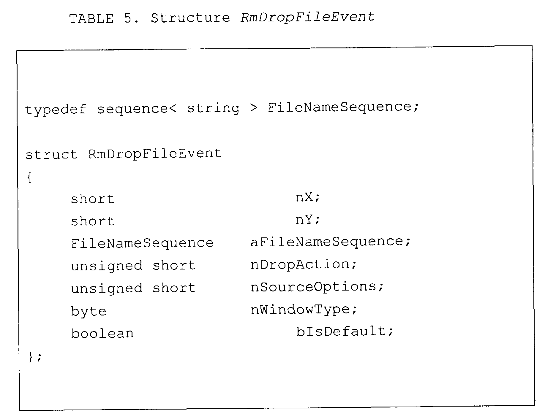
and uses a structure RmDropFileEvent (Table 5).
Interface XEventHdl includes methods MouseButtonUp,
MouseButttonDown, MouseMove, MouseWheel, KeyInput,
KeyUp, Paint, Resize, GetFocus, LoseFocus, Close,
QueryDropFile, DropFile, and UserEvent.
-
One embodiment of structure RmDropFileEvent that is
passed in the call to method RmDropFileEvent is
presented in Table 5.
-
Structures used in interface
XRmFrameWindow (Table 1 and
Fig. 7) include structure RmFrameResolutions (Table 6)
and structure IDLKeyNameInfo (Table 7).
-
As illustrated in Fig. 6, class RmFrameWindow includes
remote output device interface
XRmOutputDevice
(Table 8). Interface
XRmOutputDevice inherits from
interface
XInterface (Table 2), and uses structures
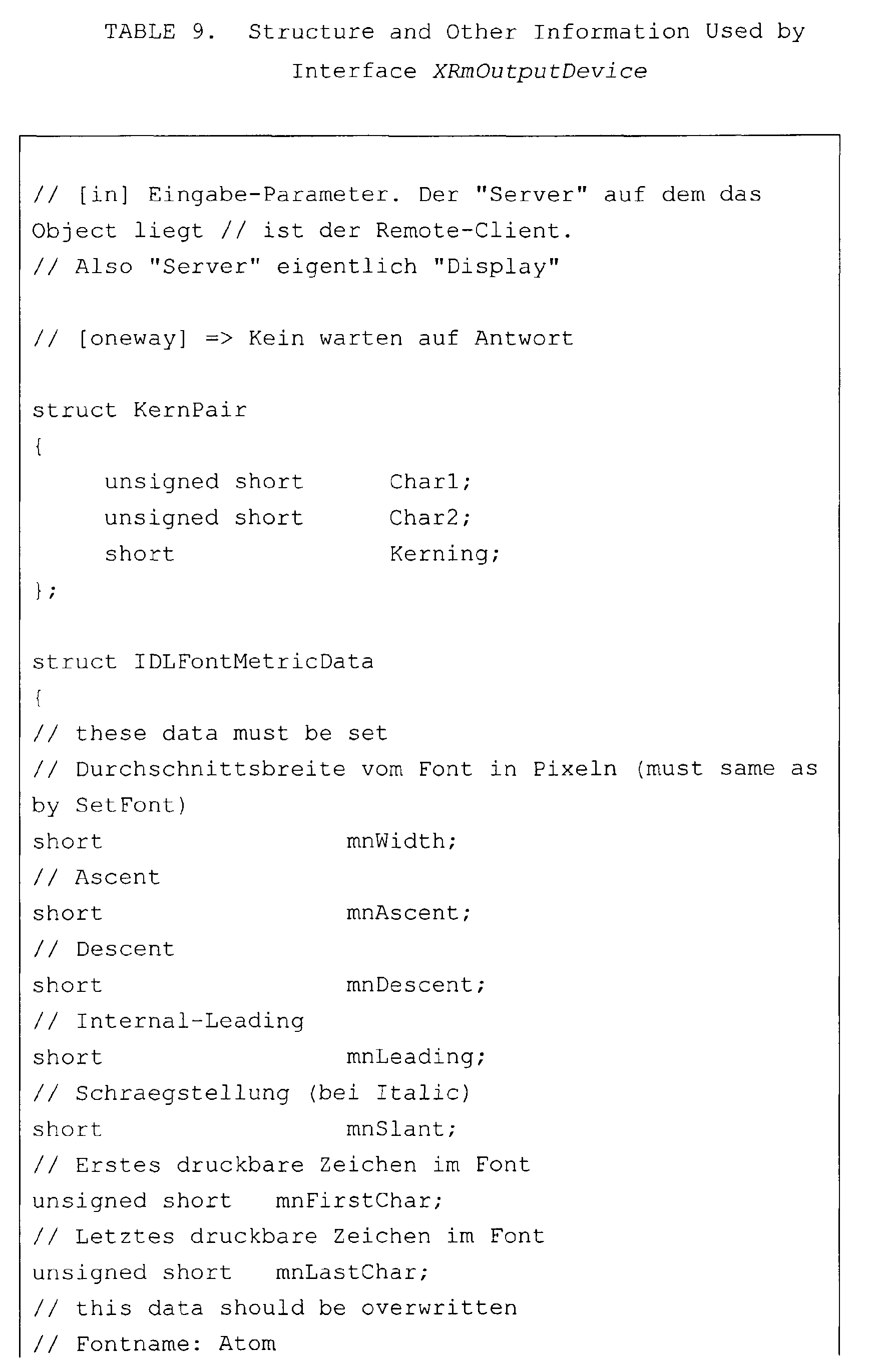
IDLFontMetricData, KernPair, IDLFontData, IDLFont
(Table 9). In the embodiment of Table 8, interface
XRmOutputDevice includes methods QuerySvOutputDevicePtr,
SetClipRegion, ResetClipRegion, GetResolution,
GetCharWidth, GetFontMetric, GetKernPairs,
GetDevFontList, AddFontAtom, GetGlyphBoundRect,
GetGlyphOutline, GetPixel, GetPixelArray, SetFont,
SetTextColor, SetLineColor, SetFillColor, SetRasterOp,
CopyArea, CopyBits, Invert, InvertPolygon,
InvertTracking, InvertTrackingPolygon, DrawPixel,
DrawColoredPixel, DrawPixelArray, DrawLine, DrawRect,
DrawPolyLine, DrawPolygon, DrawPolyPolygon, DrawEllipse,
DrawArc, DrawPie, DrawCord, DrawGradient,
DrawPolyPolyGradient, DrawPolyPolyHatch, DrawText,
DrawTextArray, DrawWaveLine, DrawGrid,
DrawPolyPolyTransparent, and Draw2ColorFrame.
-
In one embodiment, method GetFontMetric (Table 8) gets
the general metrics of the current font. If the value
of inputs nFirstChar and nLastChar are not equal, member
maCharWidths of output structure IDLFontMetricData
(Table 9) is filled as it would be in a call by method
GetCharWidth and so saves one synchronous call. If the
Boolean input value of variable bGetKernPairs is true,
member maKerningPairs of output structure
IDLFontMetricData is filled as it would be in a call to
method GetKernPairs, and this saves another synchronous
call.
-
In method AddFontAtom, Type is a FontAtomType; Name is
the new atom string; and Atom the new atomic value
-
In Table 9, a brief description of given of the values
in the various structures.
-
In Figure 6, class
Clientfactory includes interface
XMultiInstanceFactory (Table 10 and Fig. 7). Class
ClientFactory is called by an object BeanFrame to
generate multiple instances of class
RmFrameWindow.
Interface
XMultiInskanceFactory inherits from interface
XInterface (Table 2).
-
In Figure 6, class ServiceFactory include interface
XMultiServiceFactory (Table 11 and Fig. 7). Class
ServiceFactory is called by an object connector to
generate objects LoginService and BeanService.
-
Interface
XMultiServiceFactory inherits from interface
Xlnterface (Table 2) and throws an exception Exception
(Table 12).
-
The service factory objects support this interface for
creating components by a specifying string, i.e. the
service name. In the embodiment of Table 11, interface
XMultiServiceFackory includes methods createInstance,
createInstanceWithArguments, and
getAvailableServiceNames.
-
Method createInstance creates an instance of a component
which supports the services specified by the factory.
Input parameter ServiceSpecifier is a service name that
specifies the service that should be created by this
factory.
-
Method createInstanceWithArguments creates an instance
of a component which supports the services specified by
the factory. Input parameter aArguments is the values
of the arguments that depend on the service
specification of the factory. Normally the factory
delegates the arguments to the method init() of the
created instance. The factory is explicitly allowed to
modify, delete or add arguments. The conversion rules
of the arguments are specified by a converter service.
Input parameter ServiceSpecifier is a service name that
specifies the service that should be created by this
factory.
-
Method getAvailableServiceNames returns a sequence of
all service identifiers, which can be instantiated.
-
Table 12 presents one embodiment of exception
Exception
that is used by interface
XMultiServiceFactory.
In this embodiment, exception
Exception is the basic
exception from which all other exceptions are derived.
Parameter Message specifies a detailed message of the
exception or an empty string if the callee does not
describe the exception. Context is an object that
describes the reason for the exception. Object Context
may be NULL if the callee does not describe the
exception.
-
Service LoginService that is instantiated by object
ServiceFactory of the daemon includes an interface
XLogin (Table 13 and Fig. 7). Interface
XLogin inherits
from interface
Xlnterface and uses an enumeration
ResultofLogin.
-
In the embodiment of Table 13, interface XLogin includes
methods installationHasBeenCompleted,
completeInstallation, login, and getQualifiedNameOfUser.
-
Class BeanService includes an interface
XRmStarOffice in
the embodiment of Figure 6. One embodiment of interface
XRmStarOffice is presented in Table 14. Interface
XRmStarOffice inherits from interface
XInterface and
uses interfaces
XMultiServiceFactory (Table 11) and
XRmFrameWindow (Table 1). See Figure 7.
-
In the embodiment of Table 14, interface XRmStarOffice
includes methods Start, SetUserInfoForPrinting,
AddRemotePrinter, and CreateBeanWindow. Method start
receives as input a reference to object ClientFactory, a
user name, a password, identification of a file server,
and a specification of the application that is to be
started, e.g., parameters application name, application
parameters, application language, and version. Method
CreateBeanWindow receives a reference to object
RmFrameWindow, and object ClientFactory as inputs.
-
Class BeanFrame (Fig. 6) includes two interfaces,
interface XFrame (Table 15) and interface
XDispatchProvider (Table 62 and Fig. 9). In the
embodiment of Table 15, interface XFrame inherits from
interface XComponent (Table 16). Interface XFrame uses
interfaces XWindow (Table 19), XController (Table 53 and
Fig. 8C), and XFrameActionListener (Table 59 and Fig.
8C). As illustrated in Figures 8A to 8C, each of these
interfaces uses other interfaces, structures,
exceptions, and enumerations that are described more
completely below.
-
In the embodiment of Table 15, interface
XFrame includes
methods initialize, setCreator, getCreator, getName,
setName, findFrame, isTop, activate, deactivate,
setComponent, getComponentWindow, getController,
contextChanged, addFrameActionListener, and
removeFrameActionListener
-
Interface XFrame makes it possible to control a frame.
Method initialize is called to initialize the frame
within a window. Method getContainerWindow provides
access to the window of the frame. Normally this is
used as the parent window of the controller window.
Method setCreator sets the frame container that created
this frame. Only the creator is allowed to call method
setCreator. Method getCreator returns the frame
container that created this frame. Method getName
returns the programmatic name of this frame. Method
setName sets the name of the frame. Normally, the name
of the frame is set initially.
-
Method findFrame searches for a frame with the specified
name. Frames may contain other frames, e.g., a
frameset, and may be contained in other frames. This
hierarchy is searched with this method. First some
special names are taken into account, i.e. "","_self",
"_top", "_active" etc., flag nSearchFlags is ignored
when comparing these names with parameter
aTargetFrameName, and further steps are controlled by
flag nSearchFlags. If allowed, the name of the frame
itself is compared with the desired one, then (again, if
allowed )the method is called for all children of the
frame. Finally, the method may be called for the parent
frame (if allowed). If no frame with the given name is
found, a new top frame is created if this is not
suppressed by a special value of flag FrameSearchFlag.
The new frame also gets the desired name.
-
Method isTop determines if the frame is a top frame. In
general, a top frame is the frame which is a direct
child of a task frame or which does not have a parent.
If a frame returns for this method, all calls have to
stop the search at such a frame unless the flag
FrameSearchFlag::TASKS is set.
-
Method activate activates this frame and thus the
component within. At first, the frame sets itself as
the active frame of its creator by calling
FrameAction::FRAME_ACTIVATED. The component within this
frame may listen to this event to grab the focus on
activation. For simple components, this can be done by
a Frame Loader. Finally, most frames may grab the focus
to one of its windows or forward the activation to a
sub-frame.
-
Method deactivate is called by the creator frame when
another sub-frame is activated. At first the frame
deactivates its active sub-frame, if any, and then
broadcasts a Frame Action Event with
FrameAction::FRAME_DEACTIVATING.
-
Method isActive determines if the frame is active.
Method setComponent sets a new component into the frame.
Method getComponentWindow returns the current visible
component in this frame. The frame is the owner of the
window. Method getController returns the current
controller within this frame. Normally, it is set by a
frame loader.
-
Method contextChanged notifies the frame that the
context of the controller within this frame changed
(i.e. the selection). According to a call to this
interface, the frame calls with
FrameAction::CONTEXT_CHANGED to all listeners, which are
registered using this frame. For external controllers,
this event can be used to requery dispatches.
-
Method addFrameActionListener registers an event
listener, which is called when certain things happen to
the components within this frame or within sub-frames of
this frame. For example, it is possible to determine
instantiation/destruction and activation/deactivation of
components. Method removeFrameActionListener
unregisters an event listener, which was registered with
addFrameActionListener ().
-
Interface
XFrame inherits from interface
XComponent.
One embodiment of interface
XComponent is presented in
Table 16. Interface
XComponent inherits from interface
XInterface (Table 2) and uses interface
XEventListener
that in turn uses structure
EventObject. See Figure 8A.
-
Interface XComponent controls the lifetime of
components. Actually the real lifetime of an object is
controlled by references kept on interfaces of the
object. There are two distinct meanings in keeping a
reference to an interface: first is to own the object;
and second is to know the object.
-
To prevent cyclic references from resulting in failure
to destroy an object, references of interfaces to the
object are allowed only (i) by the owner, (ii) if the
reference is very temporary, or (iii) you are registered
as an Event Listener at that object and cleared the
reference when "disposing" is called.
-
An owner of an object calls method dispose to dispose of
the object. Only the owner of the object calls method
dispose if the object should be destroyed. All objects
and components must release the references to the
objects. If the object is a broadcaster, all listeners
are removed and method XEventListener::disposing() is
called on all listeners.
-
Due to the importance of the concept of method
XComponent::dispose(), a figurative example is provided.
Imagine there was a hole in the floor and some people
around it were holding a box (our component). Everyone
who holds the box for a longer time than just
temporarily (i.e. to put something in or get something
out) has to watch a light bulb, which is attached to the
box (listening to event XEventListener::disposing()).
Now, when the owner of the box switched the light on
(calling method XComponent::dispose ()), everybody
holding the box had to take their hands off (clear the
interface handles). If and only if everyone did that,
did the box fall (getting deleted). However, only the
owner is allowed to switch the light on! After method
dispose is called, the instance has to throw exception
DisposedException for all non-event-method calls and
event-method calls have to be ignored.
-
The following is an example of one embodiment.
-
Method addEventListener adds an event listener to the
listener list for the object. The broadcaster fires the
disposing method of this listener if method dispose() is
called. Conversely, method removeEventListener removes
an event listener from the listener list for the object.
-
As described above, interface
XComponent uses interface
XEventListener (Table 17.)
-
Interface
XEventListener (Table 17) inherits from
interface
XInterface (Table 2). Interface
XEventListener is a tagging interface that all event
listener interfaces must extend. Method disposing is
called when the broadcaster is about to be disposed.
All listeners and all other objects, which reference the
broadcaster should release the references. One
embodiment of structure
EventObject is presented in
Table 18.
-
Structure EventObject specifies the base for all event
objects and identifies the source of the event. Field
Source refers to the object that fired the event.
-
As explained above, interface
XWindow (Table 19) is used
by interface
XFrame (Table 15). See also Fig. 8A. In
the embodiment of Table 19, interface
XWindow inherits
from interface
XComponent (Table 16) and uses interfaces
XWindowListener (Table 21),
XFocusListener (Table 23),
XKeyListener (Table 25),
XMouseListener (Table 28),
XMouseMotionListener (Table 30), and
XPaintListener
(Table 31), and structure
Rectangle (Table 20), each of
which is described herein.
-
Interface XWindow (Table 19) specifies the basic
operations for a window component. A window is a
rectangular region on an output device with a position,
size, and internal coordinate system. The main sense of
a window is to receive events from the user.
-
Method setPosSize sets the outer bounds of the window.
Method getPosSize returns the outer bounds of the
window. Method setVisible shows or hides the window
depending on the parameter. Method setEnable enables or
disables the window depending on the parameter. Method
setFocus sets the focus to the window. Method
addWindowListener adds the specified component listener
to receive component events from this window component.
Method removeWindowListener removes the specified
listener so it no longer receives component events from
this window component. Method addFocusListener adds the
specified focus listener to receive focus events from
this window component. Method removeFocusListener
removes the specified focus listener so it no longer
receives focus events from this component. Method
addKeyListener adds the specified key listener to
receive key events from this component. Method
removeKeyListener removes the specified key listener so
it no longer receives key events from this component.
Method addMouseListener adds the specified mouse
listener to receive mouse events from this component.
Method removeMouseListener removes the specified mouse
listener so it no longer receives mouse events from this
component. Method addMouseMotionListener adds the
specified mouse motion listener to receive mouse motion
events from this component. Method
removeMouseMotionListener removes the specified mouse
motion listener so it no longer receives mouse motion
events from this component. Method addPaintListener
adds the specified paint listener to receive paint
events from this component. Method removePaintListener
removes the specified paint listener so it no longer
receives paint events from this component.
-
Structure
Rectangle (Table 20) specifies a rectangular
area by position and size. Field Y specifies the y-coordinate.
Field Width specifies the width. Field
Height specifies the height.
-
An embodiment of interface
XWindowListener that is used
in the above embodiment of interface
XWindow (Table 19)
is presented in Table 21. Interface
XWindowListener
inherits from interface
XEventListener (Table 17) and
uses structure
WindowEvent (Table 22.)
-
Interface XWindowListener makes it possible to receive
window events. Component events are provided only for
notification purposes. Moves and resizes are handled
internally by the window component, so that the GUI
layout works properly independent of whether a program
registers such a listener. Method windowResized is
invoked when the window has been resized. Method
windowMoved is invoked when the window has been moved.
Method windowShown is invoked when the window has been
shown. Method windowHidden is invoked when the window
has been hidden.
-
One embodiment of structure
WindowEvent used in Table 21
is presented in Table 22.
-
Structure WindowEvent specifies the component-level
keyboard event and inherits from structure EventObject
(Table 18). Field X specifies the outer X-position of
the window. Field Y specifies the outer Y-position of
the window. Field Width specifies the outer (total)
width of the window. Field Height specifies the outer
(total) height of the window. Field LeftInset specifies
the inset from the left. The inset is the distance
between the outer and the inner window, in other words
in this case it is the width of the left border. Field
TopInset specifies the inset from the top. The inset is
the distance between the outer and the inner window, in
other words in this case it is the height of the top
border. Field RightInset specifies the inset from the
right. The inset is the distance between the outer and
the inner window, in other words in this case it is the
width of the right border. Field BottomInset specifies
the inset from the bottom. The inset is the distance
between the outer and the inner window, in other words
in this case it is the height of the bottom border.
-
An embodiment of interface
XFocusListener that is used
in the above embodiment of interface
XWindow (Table 19)
is presented in Table 23. Interface
XFocusListener
inherits from interface
XEventListener (Table 17) and
uses structure FocusEvent (Table 24.)
-
Interface XFocusListener makes it possible to receive
keyboard focus events. The window, which has the
keyboard focus, is the window, which gets the keyboard
events. Method focusGained is invoked when a window
gains the keyboard focus. Method focusLost is invoked
when a window loses the keyboard focus.
-
One embodiment of structure
FocusEvent used in Table 23
is presented in Table 24.
-
Structure FocusEvent specifies a keyboard focus event,
and inherits from structure EventObject (Table 18).
There are two levels of focus change events: permanent
and temporary. Permanent focus change events occur when
focus is directly moved from one component to another,
such as through calls to method requestFocus() or as the
user uses the Tab key to traverse components. Temporary
focus change events occur when focus is gained or lost
for a component as the indirect result of another
operation, such as window deactivation or a scrollbar
drag. In this case, the original focus state is
automatically restored once that operation is finished,
or for the case of window deactivation, when the window
is reactivated. Both permanent and temporary focus
events are delivered using the FOCUS_GAINED and
FOCUS_LOST event ids; the levels may be distinguished in
the event using the method isTemporary()
-
Field FocusFlags specifies the reason for the focus
change as an arithmetic, or combination of
FocusChangeReason. Field NextFocus contains the window
which gets the focus on a lose focus event. Field
Temporary specifies if this focus change event is a
temporary change.
-
An embodiment of interface
XKeyListener that is used in
the above embodiment of interface
XWindow (Table 19) is
presented in Table 25. Interface
XKeyListener inherits
from interface
XEventListener (Table 17) and uses
structure KeyEvent (Table 24.) that in turn inherits
from structure
InputEvent (Table 27).
-
Interface XKeyListener makes it possible to receive
keyboard events. Method keyPressed is invoked when a
key has been pressed. Method keyReleased is invoked
when a key has been released.
-
The embodiment of structure
KeyEvent in Table 26
inherits from structure
InputEvent (Table 27), as
described above. Structure
KeyEvent specifies the
component-level keyboard event. Field KeyCode contains
the integer code representing the key of the event.
This is a constant from the constant group Key. Field
KeyChar contains the Unicode character generated by this
event or 0. Field KeyFunc contains the function type of
the key event. This is a constant from the constant
group KeyFunction.
-
Structure
InputEvent is the root event class for all
component-level input events and inherits from structure
EventObject (Table 18). Input events are delivered to
listeners before they are processed normally by the
source where they originated. Structure
InputEvent
contains the modifier keys, which were pressed while the
event occurred, i.e., zero or more constants from the
KeyModifier group.
-
An embodiment of interface
XMouseListener that is used
in the above embodiment of interface
XWindow (Table 19)
is presented in Table 28. Interface
XMouseListener
inherits from interface
XEventListener (Table 17) and
uses structure
MouseEvent (Table 29.) that in turn
inherits from structure
InputEvent (Table 27).
-
Interface XMouseListener makes it possible to receive
events from the mouse in a certain window. Method
mousePressed is invoked when a mouse button has been
pressed on a window. Method mouseReleased is invoked
when a mouse button has been released on a window.
Method mouseEntered is invoked when the mouse enters a
window. Method mouseExited is invoked when the mouse
exits a window.
-
The embodiment of structure
MouseEvent in Table 29
inherits from structure
InputEvent (Table 27).
-
Structure MouseEvent specifies an event from the mouse.
Field Buttons contains the pressed mouse buttons, which
are zero or more constants from the group MouseButton.
Field X contains the x coordinate location of the mouse.
Field Y contains the y coordinate location of the mouse.
Field ClickCount contains the number of mouse clicks
associated with event. Field PopupTrigger specifies if
this event is a popup-menu trigger event.
-
An embodiment of interface
XMouseMotionListener that is
used in the above embodiment of interface
XWindow
(Table 19) is presented in Table 30. Interface
XMouseMotionListener inherits from interface
XEventListener (Table 17) and uses structure
MouseEvent
(Table 29).
-
Interface XMouseMotionListener makes it possible to
receive mouse motion events on a window. Method
mouseDragged is invoked when a mouse button is pressed
on a window and then dragged. Mouse drag events
continue to be delivered to the window where the first
event originated until the mouse button is released
independent of whether the mouse position is within the
bounds of the window. Method MouseMoved is invoked when
the mouse button has been moved on a window with no
buttons down.
-
An embodiment of interface
XPaintListener that is used
in the above embodiment of interface
XWindow (Table 19)
is presented in Table 31. Interface
XPaintListener
inherits from interface
XEventListener (Table 17) and
uses structure
PaintEvent (Table 32) that inherits from
structure
EventObject (Table 18) and structure
Rectangle
(Table 20). See Figure 8B.
-
Interface
XPaintListener makes it possible to receive
paint events. Method WindowPaint is called when a
region of the window becomes invalid, for example,
because another window was moved away.
-
Structure PaintEvent specifies the paint event for a
component. This event is a special type, which is used
to ensure that paint/update method calls are serialized
along with the other events delivered from the event
queue. Field UpdateRect contains the rectangle area,
which needs to be repainted. Field Count contains the
number of paint events that follows this event if it is
a multiple PaintEvent. Paint events can be collected
until Count is zero.
-
An embodiment of interface
XFramesSupplier that is used
in the above embodiment of interface
XWindow (Table 19)
is presented in Table 33. Interface
XFramesSupplier
inherits from interface XFrame (Table 15) and uses
interface
XFrames that in turn inherits from several
other interfaces as illustrated in Figure 8B, and uses
several structures, enumerations, and exceptions. One
embodiment of each of these interfaces, structures,
enumeration, and exceptions are described herein.
-
Method getFrames returns the collection of (sub-)
frames, which is represented by a container
FramesContainer. Method getActiveFrame returns the sub-frame,
which is active within this frame. This may be
the frame itself. The active frame is defined as the
frame, which contains (recursively) the window with the
focus. If no window within the frame contains the
focus, this method returns the last frame, which had the
focus. If no containing window ever had the focus, the
first frame within this frame is returned.
-
Method setActive Frame is called on activation of a
direct sub-frame. This method is allowed to be called
only by a sub-frame. After this call, the frame
specified by input parameter xFrame is returned. In
general this method first calls the method at the
creator frame with this as the current argument. Then
it broadcasts the FrameActionEvent
FrameAction::FRAME_ACTIVATED.
-
In the embodiment of Table 34, interface
XFrames
inherits from interface
XIndexAccess (Table 35).
Interface
XFrames manages and creates frames. Frames
may contain other frames by implementing an interface
XFrames and may be contained in other frames.
-
Method append appends the specified Frame to a list of
sub-frames. Method queryFrames returns all child frames
of the container, which are intended to be visible to
other objects. The content of the sequence may be
limited by the caller through the flag FrameSearchFlag.
-
Method remove removes the frame from its container. The
creator attribute of the frame must be reset by the
caller of this method.
-
The embodiment of interface
XIndexAccess in Table 35
provides access to the elements of a collection through
an index. This interface should only be used if the
data structure itself is indexed.
-
Method getCount returns the number of elements. Method
getByIndex returns the element at the specified index.
Parameter Index specifies the position in the array.
The first index is 0. Method getByIndex throws
com::sun::star::lang::IndexOutOfBoundsException
(Table 52) if the index is not valid. Method getByIndex
throws com::sun::star::lang::WrappedTargetException
(Table 49), if the implementation has internal reasons
for exceptions that are wrapped in exception
WrappedTargetException.
-
In this embodiment, interface
XElementAccess is the base
interface of all collection interfaces.
-
Interface XElementAccess inherits from interface
XInterface (Table 2). Method getElementType returns the
type of the elements. Void means that the container is
a multi-type container and the exact types with this
interface cannot be determined with this method. Method
hasElements returns <TRUE> if the object contain
elements, otherwise <FALSE>.
-
One embodiment of interface
XIdlClass is presented in
Table 37. Interface
XIdlClass provides information
about a type or module. Every array also belongs to a
type that is reflected as an XIdlClass object that is
shared by all arrays with the same element type and
number of dimensions. Finally, any of the primitive IDL
types are also represented as XIdlClass objects. This
includes "void, any, boolean, char, float, double,
octet, short, long, hyper, unsigned octet, unsigned
short, unsigned long" and "unsigned hyper". Interface
XIdlClass inherits from interface
XInterface (Table 2)
-
Method getClasses returns all types and modules, which
are declared in this class. Method getClass returns a
type or module with the given name that is declared in
this class. Method equals returns <TRUE> if the
instances describe the same type, otherwise <FALSE>.
Method isAssignableFrom tests if the parameter xType is
a subclass of this class. Method getTypeClass returns
the type that this instance represents. Method getName
returns the fully qualified name of the type of object
(class, interface, array, sequence, struct, union, enum
or primitive) represented by this XIdlClass object.
Method getUik returns the UIK from this type. If the
type has no UIK, the returned UIK is zero.
-
If this object represents an interface or a class, the
objects that represent the superclasses or
superinterfaces of that class are returned by method
getSuperclasses. If this object is the one that
represents the topmost class or interface, an empty
sequence is returned.
-
Method getInterfaces determines the interfaces
implemented by the class or interface represented by
this object. If the class or interface implements no
interfaces, the method returns a sequence of length 0.
-
If this class represents an array or sequence type,
method GetComponentType returns the XIdlClass object
representing the component type of the array or
sequence; otherwise it returns null. Method getField
returns an XIdlField object that reflects the specified
member field of the class, interface, struct, union,
enum or exception represented by this XIdlClass object.
If a field with the specified name is not found, 0 is
returned. The field to be reflected is located by
searching all the member fields of the class, interface,
struct, union, enum or exception represented by this
XIdlClass object for a field with the specified name or
for NULL, if a field with the specified name is not
found. Parameter aName specifies the simple name of
the desired field.
-
Method getFields returns a sequence containing Field
objects reflecting all the accessible fields of the
class, interface, struct, union or enum represented by
this XIdlClass object. Method getFields returns a
sequence of length 0 if the class or interface has no
accessible fields, or if it represents an array, a
sequence or a primitive type. Specifically, if this
XIdlClass object represents a class, this method returns
the fields of this class and of all its superclasses.
If this XIdlClass object represents an interface, the
method returns the fields of this interface and of all
its superinterfaces. If this XIdlClass object
represents an array, sequence or primitive type, this
method returns a sequence of length 0.
-
Method getMethod returns an XIdlMethod object that
reflects the specified member method of the interface
represented by this XIdlClass object. If a method with
the specified name is not found, "0" is returned. The
method to be reflected is located by searching all the
member methods of the interface represented by this
XIdlClass object for a method with the specified name.
-
Parameter aName specifies the simple name of the desired
method.
-
Method getMethods returns a sequence containing
XIdlMethod objects reflecting all the member methods of
the class or interface represented by this XIdlClass
object, including those declared by the class or
interface and those inherited from superclasses and
superinterfaces. Returns a sequence of length 0 if the
class or interface has no member methods.
-
Method getArray returns interface XIdlArray (Table 50)
to get and set the elements by index if the represented
type is an array or sequence. Method createObject
creates an instance of the type represented by this
XIdlClass object if the represented type is a basic
type, struct, enum, or sequence.
-
Enumeration
TypeClass (Table 38) describe all type
classes, which can be defined in the IDL.
-
Interface
XIdlField (Table 39) inherits from interface
XIdlMember (Table 40).
-
Method getType returns an XIdlClass object that
identifies the declared type for the field represented
by this XIdlField object. Method getAccessMode returns
an enumeration value, which denotes whether the field is
"const", "readonly", "writeonly" or "readwrite".
-
Method get returns the value of the field represented by
this field on the specified object. The underlying
field's value is obtained as follows:
- If the underlying field is a constant, the object
argument is ignored; it may be NULL;
- Otherwise, the underlying field is an instance
field.
-
-
If the specified object argument is NULL, the method
throws an "IllegalArgumentException". If the specified
object is not an instance of the class, interface,
struct, union or enum declaring the underlying field,
the method throws an "IllegalArgumentException".
Otherwise, the value is retrieved from the underlying
instance or constant.
-
Method set sets the field represented by this XIdlField
object on the specified object argument to the specified
new value. The operation proceeds as follows. If the
specified object argument is NULL, the method throws an
exception IllegalArgumentException (Table 42). If the
specified object argument is not an instance of the
class or interface declaring the underlying field, the
method throws an exception IllegalArgumentException. If
the underlying field is constant, the method throws an
exception IllegalAccessException (Table 43). If the new
value cannot be converted to the type of underlying
field by an identity or widening conversion, the method
throws an IllegalArgumentException. The field is set to
the possibly widened new value.
-
Interface
XIdlMember (Table 40) inherits from interface
XInterface (Table 2). Interface
XIdlMember makes it
possible to access members of classes dynamically.
-
Method getDeclaringClass returns the XIdlClass object
representing the class, interface, struct, union or enum
that declares the member represented by this member.
Method getName returns the fully qualified name of the
type (class, interface, array, sequence, struct, union,
enum or primitive) represented by this XIdlClass object,
as a string.
-
The values in enumeration
FieldAccessMode (Table 41) are
used to specify the kind of attribute or property.
-
Exception
IllegalArgumentException (Table 42) is thrown
to indicate that a method has passed an illegal or
inappropriate argument. Exception
IllegalArgumentException inherits from exception
Exception (Table 12). Field ArgumentPosition identifies
the position of the illegal argument. This field is -1
if the position is not known.
-
Exception
IllegalAccessException (Table 43) is thrown
when an application tries to change a constant property.
Exception
IllegalAccessException inherits from exception
Exception (Table 12).
-
Interface
XIdlMethod (Table 44) inherits from interface
XIdlMember (Table 40). Interface
XIdlMember makes it
possible to access the specification of a method
dynamically.
-
Method getReturnType returns an XIdlClass object that
represents the formal return type of the method
represented by this method object. Method
getParameterTypes returns a sequence of XIdlClass
objects that represent the formal parameter types, in
declaration order, of the method represented by this
Method object. Method getParameterTypes returns a
sequence of length 0 if the underlying method takes no
parameters.
-
Method getParameterInfos returns a sequence of ParamInfo
objects that represent all information about the formal
parameter types, in declaration order, of the method
represented by this Method object. Method
getParameterInfos returns a sequence of length 0 if the
underlying method takes no parameters.
-
Method getExceptionTypes returns a sequence of XIdlClass
objects that represent the types of the checked
exceptions thrown by the underlying method represented
by this Method object. Method getExceptionTypes returns
a sequence of length 0 if the method throws no checked
exceptions.
-
Method getMode returns an enumeration value, which
denotes whether the method is one-way or two-way.
Method invoke invokes the underlying method represented
by this method object on the specified object with the
specified parameters. Individual parameters are subject
to widening conversions as necessary.
-
Method invocation proceeds in the following order:
- If the specified object argument is NULL, the
invocation throws an IllegalArgumentException; and
- Otherwise, if the specified object argument is not
an instance of the class or interface declaring the
underlying method, the invocation throws an
exception IllegalArgumentException (Table 42).
-
-
If the number of actual parameters supplied via args is
different from the number of formal parameters required
by the underlying method, the invocation throws an
Exception IllegalArgumentException. For each actual
parameter in the supplied args array, if the parameter
value cannot be converted to the corresponding formal
parameter type by an identity or widening conversion,
the invocation throws exception
IllegalArgumentException. When the control transfers to
the underlying method and the method stops abruptly by
throwing an exception, the exception is placed in an
exception InvocationTargetException (Table 48) and
thrown in turn to the caller of the method. If the
method completes normally, the value it returns is
returned to the caller of the method. If the underlying
method returns type is void, the invocation returns
VOID.
-
Structure
ParamInfo (Table 45) describes a formal
parameter of a method.
-
The values in Enumeration
ParamMode (Table 46) are used
to specify if a formal parameter of a method is used for
input, output or both. If the value is an IN parameter,
data can only transferred from the callee to the caller.
If the value is an OUT parameter, data can only
transferred from the caller to the callee. If value is
an INOUT parameter, data can transferred in both
directions.
-
The values in Enumeration MethodMode (Table 47) are used
to specify the calling mode of a method. If the value
is an ONEWAY parameter, the method call may be
asynchronous. If the value is a TWOWAY parameter, the
method call is synchronous.
-
Exception
InvocationTargetException (Table 48) is a
checked exception that wraps another exception.
Typically such exceptions are thrown by an invoked
method or constructor. Exception
InvocationTargetException inherits from exception
WrappedTargetException (Table 49).
-
Exception
WrappedTargetException (Table 49) is a checked
exception that wraps an exception thrown by the original
target. Normally this exception is declared for generic
methods. Exception
WrappedTargetException inherits from
exception
Exception(Table 12).
-
Interface
XIdlArray (Table 50) provides methods to
dynamically access arrays. Interface
XIdlArray inherits
from interface
XInterface (Table 2).
-
Method realloc in interface XIdlArray changes the size
of the array to the new size. If the new length is
greater, the additional elements are default
constructed, otherwise the elements are destructed.
Method realloc throws an exception
IllegalArgumentException (Table 42) if the specified
object is not an array or if the specified object is
null.
-
Method getLen in interface XIdlArray returns the number
of elements in the array. Method getLen throws an
exception IllegalArgumentException (Table 42) if the
specified object is not an array or if the specified
object is null.
-
Method get in interface XIdlArray returns the value of
the indexed component in the specified array object.
Method get throws exception IllegalArgumentException, if
the specified object is not an array or if the specified
object is null. Method get throws exception
ArrayIndexOutOfBoundsException (Table 51), if the
specified index argument is negative, or if the
specified index argument is greater than or equal to the
length of the specified array.
-
Method set in interface XIdlArray sets the value of the
indexed component of the specified array object to the
specified new value. Method set throws exception
IllegalArgumentException, if the specified object is not
an array or if the specified object is null. Method set
throws exception ArrayIndexOutOfBoundsException
(Table 51), if the specified index argument is negative,
or if the specified index argument is greater than or
equal to the length of the specified array.
-
Exception
ArrayIndexOutOfBoundsException (Table 51) is
thrown to indicate that an array has been accessed with
an illegal index. The index is either negative or
greater than or equal to the size of the array.
Exception
ArrayIndexOutOfBoundsException inherits from
exception
IndexOutOfBoundsException (Table 52).
-
Exception
IndexOutOfBoundsException (Table 52) is thrown
to indicate that a container has been accessed with an
illegal index. The index is either negative or greater
than or equal to the count of the elements. Exception
IndexOutOfBoundsException inherits from exception
Exception (Table 12).
-
As explained above, interface
XFrame (Table 15) uses
interface
XController (Table 53). With interface
XController, components viewed in a frame can serve
events by supplying dispatches. Interface
XController
inherits from interface
XComponent (Table 16).
-
Method attachFrame (Table 53) is called to attach the
controller with its managing frame. Method attachModel
is called to attach the controller to a new model.
Method suspend is called to prepare the controller for
closing the view. Method getViewData returns data that
can be used to restore the current view status. Method
restoreViewData restores the view status using the data
gotten from a previous call. Method getModel returns
the currently attached model. Method getFrame returns
the frame containing this controller.
-
In Table 54, interface
XModel represents a component,
which is created from an URL and arguments. Interface
XModel is a representation of a resource in the sense
that the interface was created/loaded from the resource.
The arguments are passed to the loader to modify its
behavior. An example for such an argument is
"AsTemplate", which loads the resource as a template for
a new document. Models can be controlled by controller
components, which are usually views of the model. If
there is at least one controller, there is by definition
a current controller, and if that controller supports
interface XSelectionSupplier, it has a current selection
too. Interface
XModel inherits from interface
XComponent (Table 16).
-
Method attachResource (Table 54) informs a model about
its resource description. Method getURL returns the URL
of the resource, which is represented by this model.
Method getArgs returns the arguments with which the
model was originally created or stored the last time.
Method connectController is called whenever a new
controller is created for this model. Interface
XComponent of the controller must be used to recognize
when the controller is deleted. Method
disconnectController is called whenever a new controller
is created for this model. Again, interface XComponent
of the controller must be used to recognize when the
controller is deleted.
-
Method lockControllers (Table 54) suspends some
notifications to the controllers, which are used for
display updates. The calls to this method may be nested
and even overlapping, but the calls must be in pairs.
While there is at least one lock remaining, some
notifications for display updates are not broadcasted.
-
Method unlockControllers (Table 54) resumes the
notifications, which were suspended by call to
lockControllers. The calls to this method may be nested
and even overlapping, but they must be in pairs. While
there is at least one lock remaining, some notifications
for display updates are not broadcasted.
-
Method hasControllersLocked (Table 54) determines if
there is at least one lock remaining. While there is at
least one lock remaining, some notifications for display
updates are not broadcasted to the controllers.
-
Method getCurrentController (Table 54) returns the
controller, which currently controls this model. If the
controller, which is active, is a controller of this
model, it will be returned. If not, the controller,
which was the last active controller of this model, is
returned. If no controller of this model ever was
active, the controller first registered is returned. If
no controller is registered for this model, NULL is
returned.
-
Method setCurrentController (Table 54) sets a registered
controller as the current controller. Method
setCurrentController throws exception
NoSuchElementException (Table 58).
-
Method getCurrentSelection (Table 54) returns the
current selection in the current controller. If there
is no current controller, the method returns NULL.
-
Structure
PropertyValue (Table 55) specifies a property
value. Field Name (Table 55) specifies the name of the
property. The name is unique within a sequence of
PropertyValues. Field Handle (Table 55) contains an
implementation-specific handle for the property. The
handle may be -1 if the implementation has no handle.
If available, the handle it can be used for fast
lookups. Field Value contains the value of the property
or void if no value is available. Field State
determines if the value comes from the object itself or
from a default, and if the value cannot be determined
exactly
-
Enumeration PropertyState (Table 56) lists the states
that a property value can have. The state consists of
two aspects: whether a value is available or void; and
whether the value is stored in the property set itself
or is a default or ambiguous.
-
Value DIRECT_VALUE (Table 56) of the property is stored
in the PropertySet itself. The property value must be
available and of the specified type. If field
PropertyAttribute in structure Property (Table 57)
contains PropertyAttribute::MAYBEVOID, then the value
may be void.
-
Value DEFAULT_VALUE (Table 56) of the property is
available from a master (e.g. template). Field
PropertyAttribute in structure Property (Table 57) must
contain the flag PropertyAttribute::MAYBEDEFAULT. The
property value must be available and of the specified
type. If field PropertyAttribute in the structure
Property contains PropertyAttribute::MAYBEVOID, the
value may be void.
-
Value AMBIGUOUS_VALUE (Table 56) of the property is only
a recommendation because there are multiple values for
this property (e.g. from a multi selection). Field
PropertyAttribute in structure
Property (Table 57) must
contain flag PropertyAttribute::MAYBEAMBIGUOUS. The
property value must be available and of the specified
type. If field Attribute in structure
Property contains
PropertyAttribute::MAYBEVOID, n the value may be void.
-
Structure
Property (Table 57) describes a property.
There are three types of properties: bound properties,
constrained properties and free properties. Field Name
specifies the name of the property. The name is unique
within an XPropertySet. Field Handle contains an
implementation specific handle for the property. The
handle may be -1 if the implementation has no handle.
Field Type contains an object that identifies the
declared type for the property. If the property has
multiple types or the type is not known, but not any,
void must be returned. Field Attributes may contain
zero or more constants of the PropertyAttribute
constants group.
-
Exception
NoSuchElementException (Table 58) is thrown by
the method to indicate that there are no more elements
in the enumeration. Exception
NoSuchElementException
inherits from exception
Exception (Table 12).
-
As explained above, interface XFrame (Table 15) uses
interface XFrameActionListener (Table 59). Interface
XFrameActionListener has to be provided if an object
wants to receive events when several things happen to
components within frames of the desktop, e.g., events of
instantiation/destruction and activation/deactivation of
components can be received.
-
Interface
XFrameActionListener inherits from interface
XEventListener (Table 17). Method frameAction is called
whenever any action occurs to a component within a
frame.
-
Event structure FrameActionEvent (Table 60) is broadcast
for action, which can happen to components within
frames. Event structure FrameActionEvent inherits from
structure EventObject (Table 18).
-
In Table 60, field Frame contains the frame in which the
event occurred. Field Action specifies the concrete
event.
Enumeration
FrameAction (Table 61) specifies the events,
which can happen to components in frames. An event
COMPONENT_ATTACHED is broadcast whenever a component is
attached to a frame. This is almost the same as the
instantiation of the component within that frame. The
component is attached to the frame immediately before
this event is broadcast. An event COMPONENT_DETACHING
is broadcast whenever a component is detaching from a
frame. This is quite the same as the destruction of the
component, which was in that frame. At the moment when
the event is broadcast the component is still attached
to the frame but in the next moment it is not attached.
An event COMPONENT_REATTACHED is broadcast whenever a
component is attached to a new model. In this case the
component remains the same but operates on a new model
component. An event FRAME_ACTIVATED is broadcast
whenever a component is activated. Activations are
broadcast from the top component, which was not active
before, down to the inner most component. An event
FRAME_DEACTIVATING broadcast immediately before the
component is deactivated. Deactivations are broadcast
from the innermost component, which does not stay active
up to the outer most component, which does not stay
active. An event CONTEXT_CHANGED is broadcast whenever
a component changed its internal context (i.e. the
selection). If the activation status within a frame
changes, this counts as a context change too. An event
FRAME_UI_ACTIVATED is broadcast by an active frame when
the active frame is getting user interface control (tool
control). An event FRAME_UI_DEACTIVATING is broadcast
by an active frame when the active frame is losing user
interface control (tool control).

-
As described above, interface
XDispatchProvider
(Table 62 and Fig. 9) is an interface of class BeanFrame
(Fig. 6). Interface
XDispatchProvider provides Dispatch
interfaces for certain functions, which are useful at
the user interface. Interface
XDispatchProvider
inherits from interface
XInterface (Table 2), and uses
interface
XDispatch (Table 63) and structures
URL
(Table 64) and
DispatchDescriptor (Table 67).
-
Method queryDispatch (Table 62) searches for an
XDispatch for the specified URL within the specified
target frame. Method queryDispatches returns multiple
dispatch interfaces for the specified descriptors at
once. Actually this method is redundant to method
DispatchProvider::queryDispatch to avoid multiple remote
calls.
-
Interface
XDispatch (Table 63) serves state information
of objects, which can be connected to controllers (e.g.
toolbox controllers). Each state change is to be
broadcast to all registered status listeners. The first
notification should be performed synchronously, if not,
controllers may flicker. State listener must be aware
of this synchronous notification. The state includes
enabled/disabled and a short descriptive text of the
function (e.g. "undo insert character"). The state is
to be broadcast whenever this state changes or the
controller should reget the value for the URL to which
it is connected. Additionally, a context-switch-event
is to be broadcast whenever the object may be out of
scope to force the state listener to requery the
XDispatch. Interface
XDispatch inherits from interface
XInterface (Table 2).
-
Method dispatch (Table 63) dispatches (executes) an URL
asynchronously. Method dispatch is only allowed to
dispatch URLs for which the current user gets the
dispatch. Additional arguments "'#..." or "?..." are
allowed.
-
The following is an example for a click-handler of a
hyperlink in a view.
Method addStatusListener (Table 63) registers a listener
of a controller for a specific URL to this object to
receive status events. This method is only allowed to
register for URLs for which the current user gets this
dispatch. Additional arguments "#..." or "?..." are
ignored. Method removeStatusListener unregisters a
listener of a controller.
-
Structure URL (Table 64) represents the original and the
parsed structure of a Uniform Resource Locator. It is
not necessary to set all of the fields; either
URL::Complete or (some of) the others are set.
Additionally, most of the other fields, like URL::User,
URL::Password or URL::Mark, are optional.
-
In Table 64, field Complete contains the unparsed
original URL, for example,
http://me:pass@www.stardivision.de:8080/pub/test/foo.txt
?a=b#xyz. Field Main contains the URL without a mark
and without arguments, for example.
http://me:pass@www.stardivision.de:8080/pub/test/foo.txt
. Field Protocol contains the protocol (scheme) of the
URL, for example, "http". Field User contains the user-identifier
of the URL, for example, "me". Field
Password contains the users password of the URL, for
example, "pass". Field Server contains the server part
of the URL, for example, "www.stardivision.de". Field
Port contains the port at the server of the URL, for
example, "8080". Field Path contains the path part of
the URL without the filename, for example, "/pub/test".
Field Name contains the filename part of the URL, for
example, "foo.txt". Field Arguments contains the
arguments part of the URL, for example, "a=b". Field
Mark contains the mark part of the URL, for example
"xyz".
-
As explained above, interface
XStatusListener (Table 65)
is used by interface
XDispatch (Table 63 and Figure 9).
Interface
XStatusListener makes it possible to receive
events when the state of a feature changes. Interface
XStatusListener inherits from interface
XEventListener
(Table 17). Method statusChanged is called when the
status of the feature changes.
-
Structure FeatureStateEvent (Table 66) is broadcast by a
controller, whenever the state of the feature changes.
Structure FeatureStateEvent inherits from structure
EventObject (Table 18).
-
In Table 66, field FeatureURL contains the URL of the
feature. Field FeatureDescriptor contains a descriptor
of the feature for the user interface. Field IsEnabled
specifies whether the feature is currently enabled or
disabled. Field Requery specifies whether the Dispatch
has to be requeried. Field State contains the state of
the feature in this dispatch. This can be, for example,
simply TRUE for a Boolean feature like underline on/off.
Some simple types like string or Boolean are useful
here for generic user interface elements, like a
checkmark in a menu.
-
Structure
DispatchDescriptor (Table 67) describes a
feature to be retrieved by an URL that has to be loaded
into a specified frame. Field FeatureURL specifies the
URL of the resource/function. Field FrameName is the
name of the target frame. Field SearchFlags is how the
target frame is to be searched.
-
In the embodiment of Figure 6, the component loaded is
StarWriter, and class StarWriter includes interface
XLoadable (Table 68 and Figure 9). Interface
XLoadable
provides functionality to implement objects, which may
be loaded. Interface
XLoadable inherits from interface
XInterface (Table 2).
-
Method load (Table 68) starts the data processing.
Method unload stops the data processing. Method reload
does a smart refresh of the object. The final state is
the same as if unload and load were called, but reload
is the more efficient way to do the same. If the object
isn't loaded, nothing happens. Method isLoaded returns
true if the object is in loaded state. Method
addLoadListener adds the specified listener to receive
events "loaded" and "unloaded." Method
removeLoadListener removes the specified listener.
-
Interface
XLoadListener (Table 69) is used in the load
listener method calls in Table 68. Interface
XLoadListener receives "loaded" and "unloaded" events
posted by a loadable object. The interface is typically
implemented by data-bound components, which want to
listen to the data source that contains their database
form. Interface
XLoadListener inherits from interface
XEventListener (Table 17).
-
Method loaded (Table 69) is invoked when the object has
successfully connected to a data source. Method
unloading is invoked when the object is about to be
unloaded. Components may use this to stop any other
event processing related to the event source before the
object is unloaded. Method unloaded is invoked after
the object has disconnected from a data source. Method
reloading is invoked when the object is about to be
reloaded. Components may use this to stop any other
event processing related to the event source until they
get the reloaded event. Method reloaded is invoked when
the object has been reloaded.
-
Class BeanWindow (Fig. 6) includes interfaces
XWindowPeer (Table 70) and
XEventHdl (Table 4).
Interface
XWindowPeer gives access to the actual window
implementation on the device. Interface
XWindowPeer
inherits from interface
XComponent (Table 16), and uses
interfaces
XToolKit (Table 71) and
XPointer (Table 88),
which are described below. See also Figures 10A
and 10B.
-
Method getToolkit (Table 70) returns the visual class,
which created this object. Method setPointer sets the
mouse pointer. Method setBackground sets the background
color. Method invalidate invalidates the whole window
using an InvalidateStyle. Method invalidateRect
invalidates a rectangular area of the window using an
InvalidateStyle.
-
Interface
XToolkit (Table 71) specifies a factory
interface for the windowing toolkit. This is similar to
the abstract window toolkit (AWT) in JAVA. Interface
XToolkit inherits from interface
XInterface (Table 2).
-
Method getDesktopWindow (Table 71) returns the desktop
window. Method getWorkArea returns the complete work
area for this toolkit. Method createWindow creates a
new window using the given descriptor. Method
createWindow throws exception
IllegalArgumentException(Table 42). Method
createWindows returns a sequence of windows, which are
newly created using the given descriptors. Method
createWindows throws exception IllegalArgumentException
Method createScreenCompatibleDevice creates a virtual
device that is compatible with the screen. Method
createRegion creates a region.
-
Structure
WindowDescriptor (Table 72) describes a
window. Field Type specifies the type of window. Field
WindowServiceName specifies the name of the component
service ("ListBox", "PushButton"). A zero length name
means that the vcl creates a blank top, a container, or
a simple window. Field Parent specifies the parent of
the component. If the Parent == 0 && ParentIndex == -1,
the window is on the desktop. Field ParentIndex
specifies the index of the parent window, if available.
If Parent == 0 and this structure is a member of an
array, this is the offset from the beginning of the
array to the parent. A value of -1 means desktop.
Field Bounds specifies the position and size of the
window. This member is ignored if the window attribute
is WA_FULLSIZE. Field WindowAttributes contains some of
the WA_
* attributes.
-
Enumeration
WindowClass (Table 73) specifies the class
of a window. Value TOP specifies a top-level window on
the desktop. It is also a container. Value MODALTOP is
a modal top-level window on the desktop. It is also a
container. Value CONTAINER is a container that may
contain other components. It is not a top window.
Value SIMPLE is the simplest window. It can be a
container.
-
Interface
XDevice (Table 74 and Figure 10A) provides
information about a graphical output device and offers a
factory for the graphics, which provides write
operations on the device. Interface
XDevice inherits
from interface
XInterface (Table 2).
-
Method createGraphics (Table 74) creates a new graphics,
which output operation direct to this device. Method
createDevice creates a new device, which is compatible
with this one. If the device does not support the
GETBITS device capability, this method returns NULL.
Method getInfo returns information about the device.
Method getFontDescriptors returns the list of available
font descriptors.
-
Method getFont (Table 74) returns information about a
font offered by this device. Parameter aDescriptor
specifies the description of a font, and specifies that
the unit of measure is pixel for this device.
-
Method createBitmap (Table 74) creates a bitmap with the
current device depth. If the specified area does not
lie entirely in the device, the bits outside are not
specified. Method createDisplayBitmap creates a device-compatible
bitmap. The data of the bitmap is in process
memory instead of in the device, so the output operation
is fast.
-
Interface
XGraphics (Table 75) provides the basic output
operation of a device. Interface
XGraphics inherits
from interface
XInterface (Table 2).
-
Method getDevice (Table 75) returns the device of this
graphics. Method getFontMetric returns the font metric
of the current font. Method setFont sets the font used
by text operations. Method selectFont creates a new
font and sets the font. Method setTextColor sets the
text color used by text operations. Method
setTextFillColor sets the fill color used by text
operations. Method setLineColor sets the line color.
Method setFillColor sets the fill color. Method
setRasterOp sets the raster operation. If the device
does not support raster operations, this call is
ignored. Method setClipRegion sets the clip region to
specified clipping. Method intersectClipRegion builds
the intersection with the current region. Method push
saves all current settings (Font, TextColor,
TextFillColor, LineColor, FillColor, RasterOp,
ClipRegion). Method pop restores all previous saved
settings. Method copy copies a rectangle of pixels from
another device into this one. Method draw draws a part
of the specified bitmap to the output device. Method
drawPixel sets a single pixel in the output device.
Method drawLine draws a line in the output device.
Method drawRect draws a rectangle in the output device.
Method drawRoundedRect draws a rectangle with rounded
corners in the output device. Method drawPolyLine draws
multiple lines in the output device at once. Method
drawPolygon draws a polygon line in the output device.
Method drawPolyPolygon draws multiple polygons in the
output device at once. Method drawEllipse draws an
ellipse in the output device. Method drawArc draws an
arc (part of a circle) in the output device. Method
drawPie draws a circular area in the output device.
Method drawChord draws a chord of a circular area in the
output device. A chord is a segment of a circle. You
get two chords from a circle if you intersect the circle
with a straight line joining two points on the circle.
Method drawGradient draws a color dispersion in the
output device. Method drawText draws text in the output
device. Method drawTextArray draws texts in the output
device using an explicit kerning table.
-
Structure SimpleFontMetric (Table 76) describes the
general metrics of a font. Field Ascent specifies the
portion of a lower case character that rises above the
height of the character "x" of the font. For example,
the letters 'b', 'd', 'h', 'k' and 'l' have an ascent
unequal to 0. Ascent is measured in pixels, thus the
font metric is device dependent. Field Descent
specifies the portion of a letter falling below the
baseline. For example, the letters 'g', 'p', and 'y'
have a descent unequal to 0. Descent is measured in
pixels, thus the font metric is device dependent. Field
Leading specifies the vertical space between lines of
this font, and is also called internal line spacing.
The leading is measured in pixels, thus the font metric
is device dependent. Field Slant specifies the slant of
the characters (italic). The slant is measured in
degrees from 0 to 359. Field FirstChar specifies the
code of the first printable character in the font.
-
Field LastChar specifies the code of the last printable
character in the font.
-
Interface
XFont (Table 77) describes a font on a
specific device. All values are in pixels within this
device. Interface
XFont inherits from interface
XInterface (Table 2).
-
Method getFontDescriptors (Table 77) returns the
description of the font. Method getFontMetric returns
additional information about the font. Method
getCharWidth returns the width of the specified
character measured in pixels for the device. Method
getCharWidths returns a sequence of the widths of
subsequent characters for this font. Method
getStringWidth returns the width of the specified string
of characters measured in pixels for the device. Method
getStringWidthArray returns the width of the specified
string of characters measured in pixels for the device.
In this method, parameter aDXArray receives the width of
every single character measured in pixels for the
device. Method getKernPairs queries the kerning pair
table.
-
Structure
FontDescriptor (Table 78) describes the
characteristics of a font. For example, this structure
can be used to select a font. Field Name specifies the
exact name of the font ("Arial", "Courier", "Frutiger").
Field Height specifies the height of the font in the
measure of the destination. Field Width specifies the
width of the font in the measure of the destination.
Field StyleName specifies the style name of the font
("Bold", "Fett", "Italic Bold"). Field Family specifies
the general style of the font. Use one value out of the
constant group FontFamily. Field CharSet specifies the
character set, which is supported by the font. Use one
value out of the constant group CharSet. Field Pitch
specifies the pitch of the font. Use one value out of
the constant group FontPitch. Field CharacterWidth
specifies the character width. Depending on the
specified width, a font that supports this width may be
selected. The value is expressed as a percentage.
Field Weight specifies the thickness of the line.
Depending on the specified weight, a font that supports
this thickness may be selected. The value is expressed
as a percentage. Field Slant specifies if there is a
character slant (italic). Field Underline uses one
value out of the constant group FontUnderline. Field
Strikeout uses one value out of the constant group
FontStrikeout. Field Orientation specifies the rotation
of the font. The unit of measure is degrees; 0 is the
baseline. Field Kerning, for requesting, it specifies
if there is a kerning table available: for selecting, it
specifies if the kerning table is to be used. Field
WordLineMode specifies if only words get underlined. A
value of TRUE means that only non-space characters get
underlined while a value of FALSE means that the spacing
also gets underlined. This property is only valid if
the property FontDescriptor::Underline is not
FontUnderline::NONE. Field Type specifies the
technology of the font representation. One or more
values out of the constant group FontType can be
combined by an arithmetical or-operation.


-
Enumeration
FontSlant (Table 79) is used to specify the
slant of a font. Value NONE specifies a font without
slant. Value OBLIQUE specifies an oblique font (slant
not designed into the font). Value ITALIC specifies an
italic font (slant designed into the font). Value
DONTKNOW specifies a font with an unknown slant. Value
REVERSE_OBLIQUE specifies a reverse oblique font (slant
not designed into the font). Value REVERSE_ITALIC
specifies a reverse italic font (slant designed into the
font).
-
The values in enumeration
RasterOperation (Table 80) are
used to specify the binary pixel-operation applied when
pixels are written to the device. Value OVERPAINT sets
all pixels as written in the output operation. Value
XOR uses the pixel written as one and the current pixel
as the other operator of an exclusive or-operation.
Value ZEROBITS causes all bits, which are affected by
this operation, to be set to 0. Value ALLBITS causes
all bits, which are affected by this operation, to be
set to 1. Value INVERT causes all bits, which are
affected by this operation, to be inverted.
-
Interface
XRegion (Table 81 and Figures 10A and 10B)
manages multiple rectangles, which make up a region.
Interface
XRegion inherits from interface
XInterface
(Table 2).
-
Method getBounds (Table 81) returns the bounding box of
the shape. Method clear makes this region an empty
region. Method move moves this region by the specified
horizontal and vertical delta. Method unionRectangle
adds the specified rectangle to this region. Method
intersectRectangle intersects the specified rectangle
with the current region. Method excludeRectangle
removes the area of the specified rectangle from this
region. Method xOrRectangle applies an exclusive-or
operation with the specified rectangle to this region.
Method unionRegion adds the specified region to this
region. Method intersectRegion intersects the specified
region with the current region. Method excludeRegion
removes the area of the specified region from this
region. Method xOrRegion applies an exclusive-or
operation with the specified region to this region.
Method getRectangles returns all rectangles, which are
making up this region.
-
Interface
XDisplayBitmap (Table 82) specifies an object
as a bitmap for which data is formatted for a specific
output device. Drawing of this bitmap is only valid on
a compatible device. Interface
XDisplayBitmap inherits
from interface
XInterface (Table 2).
-
Structure
Gradient (Table 83) describes a color
dispersion within an area. Field Style specifies the
style of the gradient. Field StartColor specifies the
color at the start point of the gradient. Field
EndColor specifies the color at the end point of the
gradient. Field Angle specifies the angle of the
gradient in 1/10 degree. Field Border specifies the
percent of the total width where just the start color is
used. Field XOffset specifies the X-coordinate, where
gradient begins. Field YOffset specifies the Y-coordinate,
where gradient begins. Field StartIntensity
specifies the intensity at the start point of the
gradient. Field EndIntensity specifies the intensity at
the end point of the gradient. Field StepCount
specifies the number of steps of change color.
-
Enumeration
GradientStyle (Table 84) specifies the style
of color dispersion. Value LINEAR specifies a linear
gradient. Value AXIAL specifies an axial gradient.
Value RADIAL specifies a radial gradient. Value
ELLIPTICAL specifies an elliptical gradient. Value
SQUARE specifies a gradient in the shape of a square.
Value RECT specifies a gradient in the shape of a
rectangle.
-
Structure
DeviceInfo (Table 85) contains information
about a device. Field Width contains the width of the
device in pixels. Field Height contains the height of
the device in pixels. Field LeftInset contains the
inset from the left. Field TopInset contains the inset
from the top. Field RightInset contains the inset from
the right. Field BottomInset contains the inset from
the bottom. Field PixelPerMeterX contains the X-axis
resolution of the device in pixel/meter. Field
PixelPerMeterY contains the Y-axis resolution of the
device in pixel/meter. Field BitsPerPixel contains the
color-depth of the device. Field Capabilities specifies
special operations, which are possible on the device.
-
Interface
XBitmap (Table 86) provides a bitmap in the
Microsoft DIB format. Interface
XBitmap inherits from
interface
XInterface (Table 2). Method getSize returns
the size of the bitmap in pixels. Method getDIB returns
the device independent bitmap. Method getMaskDIB
returns the transparence mask of the device independent
bitmap.
-
Structure
Size (Table 87) specifies the two-dimensional
size of an area using width and height. Field Width
specifies the width. Field Height specifies the height.
-
Interface
XPointer (Table 88) gives access to the type
of mouse pointer. Interface
XPointer inherits from
interface
XInterface (Table 2). Method setType selects
a SystemPointer for this mouse pointer. Method getType
returns the currently set SystemPointer of this mouse
pointer.
-
Table 89 is one embodiment of a remote virtual device
interface
XRmVirtualDevice that is included in one
embodiment of lightweight component 230.
-
Table 90 is one embodiment of interfaces
XRmBitmap and
XRmJavaBitmap that are included in one embodiment of
lightweight component 230. These interfaces are used
when a runtime environment component on server computer
system needs to display a bitmap on user device 102i.
-
Table 91 is one embodiment of interfaces
XRmPrintObserver, XRmPrinterEnvironment, XRmPrinter, and
XRmPrintSpooler that are included in one embodiment of
lightweight component 230. These interfaces are used
when a runtime environment component on server computer
system needs to print to a printer coupled to user
device 102i.
-
Table 92 is one embodiment of interface
XRmFileStream.
Table 93 is one embodiment of interface
XRmFSys. Both
of these interfaces are included in one embodiment of
lightweight component 230. These interfaces are used
when a runtime environment component reads or writes
data on a storage medium of user device 102i, or needs
to obtain information about data stored on a storage
medium of user device 102i. In this embodiment, object
BeanService 532 receives, as described above, a handle
to object ClientFactory 515. The handle to object
ClientFactory 515 to instantiate an object on the user
device to access a particular capability on the user
device, e.g., the file system, printing, sound, etc.
-
Table 94 is one embodiment of interfaces
XSoundCallBack
and XRMSound that are included in one embodiment of
lightweight component 230. These interfaces are used
when a runtime environment component needs to play
sounds on user device 102i.
-
Table 95 is one embodiment of interface
XRmStatus that
is included in one embodiment of lightweight component
230. This interfaces is used when a runtime environment
component needs the status of user device 102i.
-
Those skilled in the art will readily understand that
the operations and actions described herein represent
actions performed by a CPU of a computer in accordance
with computer instructions provided by a computer
program. Therefore, lightweight component 230 may be
implemented by a computer program causing the CPU of the
computer to carry out instructions representing the
individual operations or actions as described
hereinbefore. The computer instructions can also be
stored on a computer-readable medium, or they can be
embodied in any computer-readable medium such as any
communications link, like a transmission link to a LAN,
a link to the internet, or the like.
-
Thus, lightweight component 230 can be implemented by a
computer program comprising computer program code or
application code. This application code or computer
program code may be embodied in any form of a computer
program product. A computer program product comprises a
medium configured to store or transport this computer-readable
code, or in which this computer-readable code
may be embedded. Some examples of computer program
products are CD-ROM discs, ROM cards, floppy discs,
magnetic tapes, computer hard drives, servers on a
network, and carrier waves. The computer program
product may also comprise signals, which do not use
carrier waves, such as digital signals transmitted over
a network (including the Internet) without the use of a
carrier wave.
-
The storage medium including the applications/services
executed on a server may belong to server computer
system 100 itself. However, the storage medium also may
be removed from server computer system 100. The only
requirement is that the applications/services are
accessible by server computer system 100 so that the
application/service corresponding to lightweight
component 230 can be executed by server 100.
-
Herein, a computer memory refers to a volatile memory, a
non-volatile memory, or a combination of the two in any
one of these devices. Similarly, a computer input unit
and a display unit refer to the features providing the
required functionality to input the information
described herein, and to display the information
described herein, respectively, in any one of the
aforementioned or equivalent devices.
-
While the present invention has been explained in
connection with certain embodiments thereof, other
embodiments will be apparent to those skilled in the art
from consideration of the specification and practice of
the embodiment of the present invention disclosed
therein. It is intended that the specification and
examples be considered as exemplary only, without
limiting the spirit and scope of the invention.
-
In the following, further embodiments of the invention
will be described with respect to figs. 11 - 22.
-
The embodiments may be implemented in a software system
for providing the functionality (i.e. the services) of
runtime environment components from a server computer
system via a network to one or several client computer
systems.
-
The software system consists of two parts, one of them
being executed on a client, the other residing and being
executed on the server. The part on the server platform
makes up the runtime environment comprising a plurality
of runtime environment components which are able to
provide services. Furthermore, the part on the server
provides the necessary communication tools in order to
communicate with the client. The other part, being
executed on the client, performs mainly the
communication between the client requesting a runtime
environment component service and the part being
executed on the server which renders the runtime
environment component service requested. The server's
part of the software system is by far larger in size
than the client's part thereof. This latter part is
referred to as the 'lightweight component'. A typical
size of the software system's part on the server may be
50 to 100 Megabyte (e.g.: an office software package),
whereas the lightweight component on the client may have
a typical size of 400 Kilobyte, and may utilize only
little system resources (CPU power, memory).
-
The small size of the lightweight component makes it
attractive to download it within very short time from
the server to a client when the corresponding runtime
environment component service is actually needed. Then,
via the lightweight component, the client has access to
all the services presented by the runtime environment
components hosted on the server.
-
The lightweight component provides an application
programming interface (API) for any application program
the implementation of which on the client is allowed by
an implementation framework on the server. Two types of
lightweight components are explained in the following,
one being a standard component (referring to Figures 11
to 14), the other being a component rendering visual
functionality (referring in particular to Figures 15 to
19) .
-
Computer Software programs and parts thereof, which are
called during execution of other computer software
programs or parts thereof, are referred to as runtime
environment components. The functionality provided by
these runtime environment components to calling software
programs or parts thereof are referred to as runtime
environment component services. In many cases, runtime
environment components have a very large size. For
example, office suites comprising drawing programs and
wordprocessors as well as other tools may have sizes of
50 to 100 Megabyte which renders a distribution over the
Internet difficult. The runtime environment components
may be implemented in any suitable form. They may
consist of compiled software program code to be executed
or of script code in any programming language to be
interpreted before execution by a compiler. Runtime
environment components are typically stored and
administrated on a server.
-
The runtime environment component services, that means
the functionalities provided by runtime environment
components, which are, for example, stored on a server,
are made available for use in software programs to be
executed on, for example, clients without integrated
them into these software programs and without
distributing them together with these software programs
to the place of execution, for example, the clients.
-
Further, functionality of the runtime environment
components should is made available for all kinds of
clients whether they are powerful enough for storing or
executing the runtime environment component or not.
Further, the user of a client is not charged with the
problem whether a specific runtime environment component
is available on his client or not.
-
Reference is made to Fig. 11, which illustrates the
communication between the server 111 and an arbitrary
number of clients 112A, 112B which are connected via
communication network 113. The server 111 presents the
runtime environment component services to the clients
112A, 112B. Server 111 hosts components 1101, 1102,
1103, 1104, 1105, 1106 of the runtime environment as
well as a component 1100 for communication with the
clients 112A, 112B via a network 113. The network 113 is
here assumed to be the Internet, although any other
network may be used as well. Each client 112A, 112B is
adapted to execute (at least) one software program 1250.
-
On each of the clients 112A, 112B a lightweight
component 1210 is implemented, which provides services
of the runtime environment components 1101, 1102, 1103,
1104, 1105, 1106 hosted on server 111 to a software
program 1250 running on the clients 112A, 112B. The
communication with server 111 is performed by the
communication component 1200 via the network 113. It is
to be noted that the lightweight component 1210 may
initially not be available on the clients 112A, 112B. In
this case, the lightweight component 1210 may be
downloaded on the clients 112A, 112B, for example, from
the server 111 upon the first request for runtime
environment component services which are accessible by
means of the lightweight component 1210.
-
It is assumed that on the clients 112A, 112B a software
program 1250 (e.g.: an Internet browser) is executed.
Whenever the software program 1250 calls for a runtime
environment component, for example an API 1101 for
providing a mathematical function, the lightweight
component 1210 receives this call. The lightweight
component 1210 then transforms this call into a request
and transmits it via the communication component 1200,
the network 113 and the communication component 1100 to
the server 111, where the API component 1101 called for
is residing.
-
Fig. 12 to 14 now illustrate the processing for
presenting / providing the runtime environment component
services in more detail.
-
Referring to Fig. 12, the lightweight component 1210
receives a call for an API component 1101 from the
software program 1250 running on the client 112A. With
the call, data (e.g. arguments) necessary for performing
the requested runtime environment component service of
API component 1101 is received. The lightweight
component 1210 transforms the received call into a
request to be transmitted over the network 113 to the
server 111 which actually hosts the runtime environment,
including the now requested API component 1101.
-
The transmission of the request over the network 113 is
performed according to a predetermined transmission
protocol. The transmitted request contains the data
(e.g. arguments) from the calling software program 1250
for being processed by the API component 1101. If the
network 113 is publicly accessible, the transmission may
be encrypted according to known technologies. Further,
digital signatures can be used to provide certification
of the request mechanism being established on the client
for this runtime environment component services system.
-
The request is received by the server 111 on which the
appropriate communication component 1100 is executed.
The communication component 1100 transforms and decrypts
(if necessary) the transmitted request, performs digital
signature processing, and accesses the requested API
component 1101 implementing the desired mathematical
function. This API component 1101 is executed on the
server 111, whereby the data (e.g. arguments) received
with the request are processed. The result thereof is
encrypted (if necessary) by the communication component
1100 and transmitted from the server 111 back to the
client 112A.
-
The lightweight component 1210 on the client receives
and re-transforms the result (and decrypts it, if
necessary) and provides the result to the software
program 1250 having called for the service of the API
component 1101.
-
Thus, the lightweight component 1210 on the client 112A
delegates calls to the API component 1101, which may be
part of an implementation framework on the server 111.
The lightweight component 1210 operates hidden to the
calling software program of the client 112A. The called
runtime environment component 1101 is executed on the
server 111. However, the calling software program 1250
on the client 112A does not notice whether the execution
of the runtime environment component 1101 is local, i.e.
on the client 112A, or remote, i.e. on the server 111.
The calling software program 1250 does not need to be
modified for the use with the lightweight component
1210, since, the call for a runtime environment
component is 'intercepted' and transformed into a
suitable request to the server 111 by the lightweight
component 1210, according to the invention.
-
On the other hand, local services available on the
client 112A, including devices like printers and local
storage, can also be utilized by the runtime environment
components on the server 111, in a transparent manner.
Transformation of the call of the software program 1250
to the lightweight component 1210 and re-transformation
of the result received from the server 111 are performed
"on the fly".
-
Fig. 13 illustrates the implementation of the
lightweight component 1210. As mentioned above, the
component 1210, which is necessary for transforming the
call can be kept relatively small. It can have a small
installation size and low usage of resources compared to
the runtime environment components on the server 111.
-
Fig. 14 exemplary illustrates the transparent access of
a runtime environment component via an object component
model. The object component model handles calls by
marshaling requests for runtime environment component
services through stub objects 1200' on the client 112A
and transmitting it over the network 113 to the server
111. There, the requests are unmarshaled through proxy
objects 1100'.
-
The stub objects 1200' and the proxy objects 1100' are
generated dynamically, for example, by the communication
component 1200 and by the communication component 1100,
respectively. Therefore, a caller does not have to
implement the stub objects 1200' and the proxy objects
1100'.
-
Marshalling of a request is, in the present context,
understood as the process of embedding a request for a
runtime environment component service in a bit stream
for transmission over a network. The unmarshalling is
the inverse process of the marshalling.
-
The transmission concept through stub and proxy objects
is described in more detail in the Annex.
-
The stub / proxy object component model used here
implies that a lightweight component is able to access
any arbitrary runtime environment component 1101, 1102,
1103, 1104, 1105, 1106 available on the server 111, as
if it resided locally on the client 112A.
-
Referring to Figures 15 to 17, a further embodiment of a
lightweight component 1210 is explained. The
communication between the server 111 and the client 112A
is performed via the network 113 by the respective
communication components 1100 on the server 111, and
1200 on the client 112A. The same encryption /
decryption mechanisms as indicated above may be applied.
In addition to the basic generic lightweight component
1210 as described in connection with Figures 11 to 14,
the lightweight component 1210 may include the ability
to perform graphic interaction and to manage user
interaction. In the following, such a component is
referred to as a visual lightweight component. Such a
graphic interaction may comprise drawing visual contents
on the client 112A, for example, on a screen of a client
laptop. Again, as described above, the main part of the
processing is burdened on the runtime environment
component residing and running on the server 111.
-
The protocol which may be used for transmitting
graphical requests between the client 112A and the
server 111 is the Remote Visualization Process protocol
(RVP). RVP is a high level definition of a graphic
device defined as a set of interfaces. RVP is based
completely on a component infrastructure. This gives RVP
the ability to map functionality which a client system
is unable to support, to a service component on the
server side emulating this functionality.
-
The graphical environment may communicate with the
lightweight component 1210 through the Java Abstract
Window Toolkit layer (AWT). AWT stands for the
definition of the graphic and user interface layer for
the Java language. It is defined as a set of Java
classes and interfaces which are mapped to the concrete
implementation on different platforms. AWT is part of
the standard Java environment.
-
The service component on the server side uses a VCL
implementation as drawing engine. VCL (Visual Class
Library) is a C++ class library . It provides similar to
the AWT a set of classes and interfaces to build
graphical applications on different platforms. For every
platform there is a concrete implementation of VCL. For
the lightweight visual components, VCL provides a
special implementation, which transmits all graphical
requests for drawing over the network to a client side,
where these requests are intercepted and mapped to a
platform dependent graphic layer, which is here AWT.
-
Again, the implementation framework on the server
handles drawing and user interaction transparently to
the component.
-
Fig. 15 illustrates RVP event processing. The visual
lightweight component 1210 is embedded in a graphical
environment, the graphical environment comprising a
display software program 1250 with a graphical user
interface (GUI). The graphical user interface is
referred to as a panel. An example of an implementation
is a Java bean which is embedded in an HTML page and
rendered by a browser. This Java bean represents a view
(in a window) of an office application component (e.g.
StarOffice Writer) or another visual office component.
-
An event from the graphical environment is passed to the
AWT 1260, and then interpreted by the RVP protocol
layer, which performs communication between the client
visual lightweight component 1210 and the remote office
runtime environment component implementation 1110 on
the server platform 111. From RVP 1220 the event is
marshaled by communication component 1200 and
transmitted to the server 111. There, it is unmarshaled
and passed to the RVP 1120 by communication component
1100, and dispatched by the VCL layer 1140.
-
The runtime environment component 1110 receives the
event. After the event is dispatched, the component 1110
is able to react to the event.
-
Fig. 16 illustrates the transmission of the response of
the component 1110 on the server 111 back to the
requesting client 112A. The requested service is here a
drawing functionality which is implemented by RVP
drawing. The office component (e.g. the StarOffice
Writer) 1110 is able to draw on a panel within software
program 1250 of the client 112A using the same mechanism
as described above. The component 1110 uses the VCL 1140
as a drawing engine. The operations are transmitted
through VCL 1140, RVP 1120 and communication component
1100 on the server 111 to the client 112A. Client 112A
receives the operations and passes them to the AWT 1260
which is able to draw on the panel of the client 112A
directly.
-
Fig. 17 illustrates accessing an API as a runtime
environment component on the server 111 by the client
112A. The visual lightweight component 1210 is, in the
example described in Fig. 15 and Fig. 16, still able to
access transparently the full functionality of an API
1104 provided by the office component 1110. The request
of the lightweight component 1210 for API 1104 is handed
over to the office component 1110 through the
communication component 1200 on the client 112A and the
communication component 1100 of the server 111. Herein,
the request for the API 1104 generated by the
lightweight component 1210 may bypass RVP 1220 and AWT
1260 on the client 112A and likewise RVP 1120 and VCL
1140 on the server 111, if not drawing services are
requested. The latter would be the case, for example, if
API 1104 would provide calculation services. In order to
have the request bypass the mentioned components the
lightweight component 1210 must decide that these
components shall be bypassed. This decision can be made
by the lightweight component 1210 based on the call of
the API 1104 received from the software program 1250 and
the information that the API 1104 does not provide
drawing services. This information will regularly be
present in the lightweight component 1210, since it has
information about all runtime environment components
being available on the server 111 anyway, since it has
to request their services and receive their responses.
However, if necessary the office component 1110 may also
react to the request for API 1104 by drawing via RVP
1220 directly on the panel of client 112A.
-
An exemplary scenario for the latter might be the
following: a user on client 112A editing a text document
displayed in his browser whishes to change the font size
to 10 points throughout the whole document. For this
purpose, the client 112A uses the API 1104 to change all
fonts throughout the whole document to a size of 10
points. In this case, the office component 1110 running
on the server 111 re-calculates the display of the
document, renders the document remotely, and draws the
document on the client 112A through the RVP 1120 and RVP
1220.
-
However, if the user on client 112A changes the font
size only for newly input text lines, the currently
displayed document does not change, thus there is no
need to re-draw the whole document on the client 112A.
The event of changing the font size is passed via RVP
1120 to the office component 1104 and forces new
rendering of the document on the server 111. Since no
re-drawing of the document on the client 112A is needed,
the lightweight component 1210 does not have to take any
further action.
-
The participating components to create a Java bean
lightweight component in the frame of the office
application program package StarOffice used as a runtime
environment component are shown in Fig. 18. An
accompanying sequence diagram is supplied in Fig. 19.
The figures are reduced to show only needed relations
and methods to illustrate this specific process. A
StarOfficeBean represents a common java bean which is
derived from a java panel. It resides on the client as
the single instance Connector, which is responsible for
maintaining connections to the remote machine. All
client beans share one connection per user and server.
The OClientFactory created by the Connector is also
located at the client 112A. This enables the remote
Office Component to create elements which are specific
to the client 112A. Examples for these items range from
a simple frame window to a printer device handled
locally. Next the Connector establishes a connection to
the remote machine and starts the login process. If
succeeded the server 111 starts a StarOffice session
remotely and the Connector confirms the session with
Start(). The task of the remote MultiServiceFactory
created by the RVP Connection instance is to create
needed instances on the remote machine. Then a local
ORmFrameWindow is created and passed together with a
reference of the OClientFactory to the remote StarOffice
instance to be able for local dispatching and drawing.
By calling initialize() on the remotely created
Java Bean Frame all actions are done and the process of
creating a StarOfficeBean is completed.
-
Unlike components like CORBA objects, lightweight
components 1210 do not have any additional code for
accessing the implementing object. Also the size of a
lightweight component 1210 does not increase with the
number of accessed runtime environment components of the
implementation server framework. This introduces the
ability to offer components which expose only services
designed for a special purpose and hide complexity of
the implementation framework.
-
By applying the invention, it is possible to include for
example full word processing functionality provided by
the server 111 into any other application program 1250
running on the client computer 112A.
-
Special purposes may be applications designed for being
executed on particular clients like handheld computers
or mobile telephones, where storage and processing
capabilities are particularly limited. Nevertheless, the
whole functionality of the framework is still
accessible.
-
Furthermore, when adding new runtime environment
components to the server 111, no modification on the
client side is necessary. Through the concept of
lightweight components, a new runtime environment
component on the server is immediately callable by the
client. The components are based on a generic
lightweight component which is able to communicate with
the implementation framework via the object component
model.
-
Fig. 20 refers to an example for using the present
invention. In this example a setup is used as described
in Fig. 15 to 17. Therefore, reference numerals also
relate to components which are presented and described
in more detail in connection with Fig. 15 to 17.
However, the method according to Fig. 20 does not
correspond to the methods described along Fig. 15 to 17.
-
In this example, a user utilizes his computer system as
a client 112A. This client 112A includes a screen on
which the user can edit and process a text document. The
client 112A includes text processing software 1250 with
a limited scope of functionality and a lightweight
component 1210 which corresponds to comprehensive
services offered by an office suite software package
1110 located as runtime environment components on a
server 111 to which the client 112A is connected via a
network 113.
-
For the purposes of this example the user edits a text
document on the screen of the client 112A and changes
the font size of the text. In order to do this he inputs
his commands via a suitable input device of the client
112A, for example, a keyboard. In step 2010 the text
processing software 1250 on the client 112A requests the
service "font change" from the lightweight component
1210. The lightweight component 1210 receives this
request in step 2020. In step 2030 the lightweight
component 1210 marshals the request and transmits it via
the communication component 1200 in client 112A to the
communication component 1100 of the server 111 via the
network 113.
-
The server 111 unmarshals the request and calls the
runtime environment component 1110 in step 2040. In the
next step 2050 the component 1110 starts processing the
"font change" request. It will determine in step 2060 if
a re-drawing of the text document on the screen of the
client 112A is necessary due to the requested font
change.
-
If not, the service component 1110 will immediately
produce a result to the request in step 2080. A re-drawing
may not be necessary, if the user wants the font
change to be effective exclusively for further input
into the text document. In this case the result to be
provided by component 1110 could be a return code to the
software program 1250 which tells the software program
1250 that further input into the text document will be
processed with the new font on the screen of the client
112A.
-
If yes, for example, if the font shall be changed for
the whole text document, the component 1110 renders a
new graphical presentation of the text document in step
2061. Then, in step 2062, the output operations for the
realization of the graphical presentation are given to
the VCL 1140 by the component 1110. In step 2063 it will
be decided by VCL 1140 whether the output operations
have to be carried out in a visible area, e.g. on a
screen.
-
If this is not the case, for example, if the text
document with the font changed throughout its entire
scope would only be stored as a data file but not shown
on the screen of the client 112A, the result would be
created in step 2090 by VCL 1140. This result would be
the text document in the new form. No display on the
screen of the client 112A would be envisaged in this
case.
-
If this is the case, for example, if the text document
shall be displayed on the screen of the client 112A, the
"change font" request realized by VCL 1140 is
transmitted to RVP 1120 in step 2064. This realized
request is then, in step 2065, marshaled and sent via
communication component 1100 of server 111, via the
network 113 and via the communication component 1200 of
the client 112A to the lightweight component 1210 on the
client 112A. In step 2066 the lightweight component 1210
unmarshals the realized request. In step 2067 the
request is translated into an AWT request. This AWT
request is transmitted in step 2068 from the lightweight
component 1210 via the RVP 1220 to the AWT 1260. In step
2069 the AWT 1260 executes the transmitted AWT request.
Finally, in step 2070 the result will be transmitted to
the software program 1250 so that the text document will
be drawn on the screen of the client 112A with the new
font size.
-
Fig. 21 illustrates a non-visual lightweight component.
Non-visual means that the user of the client on which
the lightweight component is located does not receive
any hints as to its presence. He does not see it and he
can also not interact with it directly.
-
In Fig. 21 a client 2110 is shown with a screen showing,
on the left, a tree-like representation of data files
below a window, and, on the right, information given
about a certain text document which was selected by the
user by means of the tree-like representation of data
files. The client 2110 is connected via network 2120 to
a server 2130 which has access to a text processing
software program as runtime environment component 2140.
This component 2140 has in turn access to a storage
medium 2150 and to a library 2160.
-
If a user of the client 2110 wants to obtain
information, for example, number of words and lines,
author and date of this version, about a text document
chosen from the tree-like representation of data files,
he enters his request via an input device of the client
2110, for example, a keyboard of the client 2110. Then,
the non-visual lightweight component on the client 2110
will contact, as described above, via the network 2120
the server 2130 and ask for the services providing the
information requested by the user from the runtime
environment component 2140. The result provided by the
component 2140 will then be re-transmitted to the client
2110 so that the desired information - number of words
and lines; author and date of this version of the
selected text document - can be displayed on the screen
of the client 2110. The lightweight component remains
non-visual to the user of the client 2110.
Fig. 22 in contrast shows an example of a visual
lightweight component, that means a lightweight
component with which the user may interact, but which
will at least be recognized by the user in some
situations.
-
A client 2210 includes a visual lightweight component.
The client 2210 is connected via network 2220 with the
server 2230, which in turn has access to the runtime
environment component 2240 connected to storage medium
2250 and data base 2260.
-
In this example, a user of the client 2210 edits a text
document on the screen of the client 2210, as shown in
Fig. 22 on the right, besides the above described window
and tree-like representation of data files. The shown
screen representation of the text document shows in the
right middle position a small window with which the user
may manipulate the displayed text document. This window
represents the lightweight component. Here, the user may
directly interact, via the window presentation, with the
lightweight component, which is therefore referred to as
a visual lightweight component.
-
If the lightweight component is activated by a user
interaction it may contact, as described above, the
server 2230 and thereby the runtime environment 2240,
which may provide a service requested by the user by his
interaction from the client 2210.
-
Comparing a non-visual and a visual lightweight
component as above described, it may be advantageous to
use a non-visual lightweight component for processing
requests which do not require particular operations for
their fulfillment, in particular, no drawing operations
on a screen of a client. In this case, the non-visual
lightweight component may provide the response to the
request more quickly than a visual lightweight
component, since, for example, drawing operations are
not processed at all; they are not only ignored by the
client after having been processed with great efforts.
-
In the following, further embodiments will be described
with respect to Figs. 23 - 36.
-
The following embodiments enable a first software
program using a first binary specification to employ a
limited functionality of a second software program using
a second binary specification.
-
Many software programs, which are created in different
programming languages, have to communicate with each
other. For example, a first software program created in
a first programming language is able to provide tables.
It calls another software program created in a second
programming language which is able to calculate figures
which are needed in the table to be produced by the
first program. The calculation program cannot be called
by the table program, since these two programs use
different binary specifications for the communication
because of their different programming languages. The
different binary specification can be caused by
different programming languages as well as by different
compilers for the same programming language, since the
communication problems caused by a different programming
language and by different compilers for the same
programming language are comparable, if not identical.
-
The prior art solution to this problem is to provide
transformer modules for each required transformation
route, for example from a certain first binary
specification to a certain second binary specification.
Since in modern computer applications many different
software programs may be called by a certain software
program, the computer system requires a voluminous
library of transformer modules. This extensive library
needs significant storage space and regular maintenance,
since for every new binary specification which shall be
accessible a full new set of transformer modules must be
provided, in addition to the existing transformer
modules. However, most of these transformer modules are
not used frequently, so that their storage is not
efficient.
-
Furthermore, these prior art transformer modules extend
to the full functionality of the software program to be
translated from one binary specification to another. Due
to the regularly wide functionality of software programs
known transformer modules are rather voluminous and
require, when they are activated, a significant amount
of working memory and processor time from the computer
system on which they are carried out. Furthermore, the
complete translation of a software program is burdensome
and time consuming, although it is in most cases
unnecessary for the specific task to be accomplished.
-
Thus, it is desired to provide an efficient method to
enable a first software program to employ certain
functionalities of a second software program, wherein
the first and the second software program use different
binary specifications.
-
A first software program using a first binary
specification may employ a limited functionality of a
second software program using a second binary
specification with the following steps:
- a) initiating the creation of a stub, which is able to
transform commands relating to the limited
functionality of the second program between the second
binary specification and an intermediate binary
specification, using a second bridge, wherein the
second bridge provides a mapping of the second binary
specification and the intermediate binary
specification,
- b) initiating the creation of a proxy, which is able to
transform commands relating to the limited
functionality of the second program between the first
binary specification and the intermediate binary
specification, using a first bridge, wherein the first
bridge provides a mapping of the first binary
specification and the intermediate binary
specification, and
- c) initiating the arrangement of the proxy and the stub
relatively to the first program and the second program
in a manner allowing the first program to employ the
limited functionality of the second program.
-
-
Software programs generally are compiled executable
programs. Software programs are initially written in a
programming language, for example, C++ or Java or an
object model like Corba. They are compiled with
compilers corresponding to the programming language.
However, for each programming language several compilers
may be available. The binary specification in which a
software program is able to communicate with other
software programs depends on both, the programming
language and the compiler. This communication language
of a software program is the language referred herein as
the binary specification used by a software program, for
example, the first, the second and the intermediate
binary specification.
-
The intermediate binary specification serves as the
binary specification into and from which the
communication between the first and the second software
program will be translated. This intermediate binary
specification may be, for example, an existing binary
specification like the binary specification of a
specific compiler, but it is also possible that this
intermediate binary specification is a suitable newly
created binary specification, for example, a binary
specification which facilitates translation into and
from it.
-
According to the following embodiments the two
transformer modules, called proxy and stub, may be
created on demand, that means if and when they are
needed. This creation on demand will be initiated
directly that means by the first software program or by
means of an initiating function. This creation on demand
is considered to be dynamic, so that the commands of the
first software program may be dispatched dynamically.
The two transformer modules are at least able to
transform commands corresponding to a limited
functionality of the second software program. Since the
first software program employs in most cases only a part
of the functionality of the second software program, the
two transformer modules need to transform only commands
which correspond to this limited functionality. Here,
commands may be any kind of message initiating any kind
of activity of a software program and which may be
transmitted between the two software programs.
-
It is possible to insert further modules between these
two transformer modules. These modules may be able to
intercept the commands. This interception may be used,
for example, to add security or accounting
functionality. It is also possible to use these two
transformer modules to synchronize the commands or to
use them for debugging.
-
For the creation of the proxy and the stub mappings
between the basic commands, on which all other commands
are based, of the two pairs of participating binary
specifications are used. These pairs are the first
binary specification and the intermediate binary
specification and the second binary specification and
the intermediate binary specification. These mappings
will be provided by the bridges and may be, for example,
stored in a data base. However, the bridges may also
already be a part of the second software program. In
case these mappings cover the complete functionality of
the relevant binary specifications - which is frequently
the case - only some parts of the mapping may be
considered during the creation of the proxy and the
stub, since they relate to the above mentioned limited
functionality only.
-
After their creation the proxy and the stub are arranged
in a manner which enables the first software program to
communicate with the second software program. That means
a path of communication must be arranged from the first
software program to the proxy, from the proxy to the
stub, and finally from the stub to the second software
program. This route must regularly be accessible from
both sides, that means from the side of the first
software program as well as from the side of the second
software program.
-
In order to generate the stub the second binary
specification used by the second software program must
be known. For this purpose, the first software program
may start the second software program. This may be done
by the first program by means of a loader function which
loads the second software program. Loader functions are
well known in the prior art. A loader function is able
to initiate a software program using a certain binary
specification on demand of another software program
using a different binary specification. The loader
function may directly initiate the creation of the
required stub or it may initiate that the second
software program or an auxiliary program communicating
with the second software program creates the stub. This
is possible, if the loader function carries or supplies
by any means the information about the limited
functionality of the second software program requested
by the first software program.
-
The creation of the stub may be carried out by the
second software program or by any sub-program of the
second software program. It is possible that this sub-program
exists already in the second software program.
However, this sub-program may as well be procured or
generated by the second software program in response to
a request of the first software.
-
After the creation of the stub, the initiated second
software program or its sub-program creating the stub
may inform the first software program that the stub has
been created. This may initiate the creation of the
proxy by the first software program or any suitable sub-program,
as it was described above for the creation of
the stub.
-
The proxy may be created by the first software program
or a sub-program, a function thereof. The sub-program of
the first software program must consider the bridge for
the transformation of the first binary specification
into the intermediate binary specification and reverse
and the requested limited functionality of the second
software program. The information about the requested
limited functionality is generally available in the
first software program, because the first software
program requests this limited functionality from the
second software program.
-
In order to enable the communication between the first
software program and the second software program the
stub and the proxy may transform any commands or other
messages between these two software programs, as far as
the proxy and the stub support this functionality. This
requires the above described arrangement of the proxy
and the stub relatively to the first and the second
software program.
-
A method for employing a limited functionality of a
second software program using a second binary
specification by a first software program using a first
binary specification may include the following steps:
- a) initializing the limited functionality of the second
software program by the first software program,
- b) creating a stub, which is able to transform commands
relating to the limited functionality of the second
software program between the second binary
specification and an intermediate binary
specification, using a second bridge, wherein the
second bridge provides a mapping of the second binary
specification and the intermediate binary
specification,
- c) creating a proxy, which is able to transform commands
relating to the limited functionality of the second
software program between the first binary
specification and the intermediate binary
specification, using a first bridge, wherein the first
bridge provides a mapping of the first binary
specification and the intermediate binary
specification,
- d) transmitting an command relating to the limited
functionality from the first software program to the
proxy,
- e) transforming the command from the first binary
specification into the intermediate binary
specification by the proxy,
- f) transmitting the command transformed by the proxy from
the proxy to the stub,
- g) transforming the transmitted command from the
intermediate binary specification into the second
binary specification by the stub,
- h) transmitting the command transformed by the stub from
the stub to the second software program,
- i) carrying out the command in the second software
program and generating a response for the first
software program,
- j) transmitting the response, being in the second binary
specification, from the second software program to the
stub,
- k) transforming the response from the second binary
specification into the intermediate binary
specification by the stub,
- l) transmitting the response transformed by the stub from
the stub to the proxy,
- m) transforming the response from the intermediate binary
specification into the first binary specification by
the proxy,
- n) transmitting the response transformed by the proxy
from the proxy to the first software program.
-
-
The transmissions between the proxy and the stub and the
software programs and the proxy or the stub,
respectively, may be effected by any suitable means. It
is relevant, however, that these elements are arranged
so as to allow the communication of the two software
programs.
-
Furthermore, a method for using a stub, which is able to
transform commands relating to a limited functionality
of a second software program between a second binary
specification and an intermediate binary specification,
using a second bridge, wherein the second bridge
provides a mapping of the second binary specification
and the intermediate binary specification, is provided
for enabling a first software program using a first
binary specification to employ the limited functionality
of the second software program by further using a proxy,
which is able to transform commands relating to the
limited functionality of the second software program
between the first binary specification and the
intermediate binary specification, using a first bridge,
wherein the first bridge provides a mapping of the first
binary specification and the intermediate binary
specification, wherein the proxy and the stub are
arranged relatively to the first software program and
the second software program in a manner allowing the
first software program to employ the limited
functionality of the second software program.
-
A method for using a proxy may enable to transform
commands relating to the limited functionality of the
second software program between the first binary
specification and the intermediate binary specification,
using a first bridge, wherein the first bridge provides
a mapping of the first binary specification and the
intermediate binary specification, for enabling a first
software program using a first binary specification to
employ the limited functionality of the second software
program by further using a stub, which is able to
transform commands relating to a limited functionality
of a second software program between a second binary
specification and an intermediate binary specification,
using a second bridge, wherein the second bridge
provides a mapping of the second binary specification
and the intermediate binary specification, wherein the
proxy and the stub are arranged relatively to the first
software program and the second software program in a
manner allowing the first software program to employ the
limited functionality of the second software program.
-
A computer program, also referred to as a computer
program product, may carry out the above operations. A
computer program product comprises a medium configured
to store or transport computer readable code, or in
which computer readable code may be embedded. Some
examples of computer program product are: CD-ROM disks,
ROM-cards, floppy disks, magnetic tapes, computer hard
drives, servers on a network and carrier waves and
digital signals transmitted over a telecommunication
link or network connection.
-
Such computer program may be stored on any data carrier,
such as, for example, a disk, a CD or a hard disk of a
computer system. It is further provided a method for
using a computer system, including standard computer
systems, for carrying out the present inventive method.
Finally, a computer system may comprise a storage medium
on which a computer program for carrying out the above
operations may be stored.
-
Following, reference is made to Fig. 23. A first
software program 2301, created with any convenient
programming language, for example C++, and compiled with
a certain compiler for C++, uses a first binary
specification. This first binary specification depends
on both, the programming language and on the compiler.
The first software program 2301 may be, for example,
able to present numbers in graphical form. In order to
calculate the exact dimensions of the graphs the first
software program 2301 may want to employ a second
software program 2302, created with another programming
language, for example Java, and compiled by using a
certain compiler for Java. This second software program
2302 uses the second binary specification for
communication.
-
The use of the second software program 2302 by the first
software program 2301 requires its initialization, for
example, by calling a loader function 2305. The second
software program 2302 may then initialize its sub-program
2302a for creating the stub 2304. The sub-program
2302a must consider the limited functionality in
order to arrive at the desired stub 2304, namely a
module for transforming commands and responses relating
to the requested limited functionality. Based on this
limited functionality, the sub-program 2302a selects the
relevant mappings of the bridge 2307 between the second
binary specification and the intermediate binary
specification.
-
The first software program 2301 may correspondingly
initiate a sub-program 2301a to create the proxy 2303 in
a similar way, by employing the bridge 2306 between the
first binary specification and the intermediate binary
specification. This sub-program 2301a may be informed
about the limited functionality from the first software
program 2301. However, it may also know this limited
functionality from the second software program 2302 by
communicating via the communication channel 2308. This
channel 2308 may be any suitable real or virtual
connection which allows the transfer of data.
-
After the stub 2304 and proxy 2303 have been created
they are arranged so as to allow the communication
between the first software program 2301 and the second
software program 2302. Once this arrangement is effected
the first software program 2301 sends the command to be
transformed to the proxy 2303. The proxy 2303 may
transform this command from the first binary
specification into the intermediate binary
specification. This intermediate binary specification
corresponds, for example, to the binary UNO
specification. The proxy 2303 may transmit this command
in the intermediate binary specification to the stub
2304. The stub 2304 may transform the command from the
intermediate binary specification into the second binary
specification and may transmit the command then to the
second software program 2302.
-
The second software program 2302 may execute the
command, for example, the command to calculate the
dimensions of a graph and may generate a response for
the first software program 2301. This response may be
transformed and transmitted by the stub 2304 and the
proxy 2303 from the second software program 2302 to the
first software program 2301.
-
The arrows shown in Fig. 23 between the first software
program 2301, the proxy 2303, the stub 2304, the second
software program 2302 and the loader function 2305 show
the possible routes of communication. The arrows between
the proxy 2303 and the bridge 2306 and between the stub
2304 and the bridge 2307 represent the contribution of
the bridges 2306 and 2307 to the creation of the proxy
2303 and the stub 2304, respectively.
-
Fig. 24 represents an example for the initial
communication of a first software program 2301 and a
second software program 2302. The initial communication
between the two software programs 2301, 2302 is carried
out, before the creation of the stub 2304 and of the
proxy 2303 is initiated. Due to the different binary
specifications used by the two software programs 2301,
2302, namely the first and the second binary
specification, this initial communication will regularly
be extremely limited. It may be effected as explained
exemplary in the following.
-
In a first step 2400 the first software program 2301 may
call a loader function 2305 for the second software
program 2302. The loader function 2305 may be any known
loader function for this second software program 2302. A
loader function for a program is a software module which
"wakes up" this program so that it carries out certain
functions. Herein, the loader function may be addressed
in one binary specification and may wake up a program
using a different binary specification. However, the
loader function is not suited to provide any detailed
communication between programs using different binary
specifications.
-
The loader function 2305 may be used by the first
software program 2301 from the beginning. This is the
case, if the first software program 2301 knows or
assumes that the second software program 2302 does not
use the same binary specification as itself, namely the
first binary specification. If this knowledge is not
present in the first software program 2301, it may
simply try to call the second software program assuming
that it will understand the first binary specification.
In this case, the first software program 2301 may only
employ the loader function 2305 if the direct
communication with the second software program 2302
fails and a corresponding message is returned to the
first software program 2301.
-
In the calling step 2400 the first software program 2301
informs the loader function 2305 about the limited
functionality requested from the second software program
2302. Therefore, the loader function 2305 must be suited
to receive and carry this information. In order to
provide this information to the loader function 2305 the
first software program 2301 may hand over to the loader
function 2305 the command to be carried out by the
second software program 2302, so that the second
software program 2302 may, on receipt of the call of the
loader function 2305 decide itself which functionality
is needed, or the first software program 2301 may
provide the loader function 2305 directly with the
description of a limited functionality of the second
software program 2302 which will be required by the
first software program 2301.
-
In step 2401 the loader function 2305 contacts and
initializes a reception function of the second software
program 2302 to be able to transmit in the next step
2402 its information about the limited functionality
required from the second software program 2302. In the
next step 2403 the second software program 2302 analyses
the information received from the loader function 2305
regarding the required limited functionality. After the
analysis of the limited functionality required the
second software program 2302 initializes the creation of
a stub 2304.
-
Fig. 25 shows the creation of a stub 2304. The stub 2304
has the task to transform commands sent by first
software program 2301 to the second software program
2302 from the intermediate binary specification into the
second binary specification used by the second software
program 2302 and to transform responses sent by the
second software program 2302 back to the first software
program 2301 from the second binary specification into
the intermediate binary specification. Furthermore, the
stub 2304 may be assigned the task to transmit the
transformed commands or responses to the recipients, the
second software program 2302 or the proxy 2303,
respectively.
-
In step 2500 the second software program 2302 may
initialize a sub-program 2302a for creating the stub
2304. This sub-program 2302a may be an integral part of
the second software program 2302 or it may be as well a
separate independent software module which can be used
by this and potentially any other second software
program 2302. Accordingly, the sub-program 2302a may be
stored on the computer system or storage device on which
the second software program 2302 is stored. However, the
sub-program 2302a may also be stored on another computer
system or storage device to which the second software
program 2302 has access.
-
In step 2501 the sub-program 2302a receives from the
second software program 2302 a description of the
limited functionality required from the second software
program 2302. Then, in step 2502 the bridge 2307 between
the second binary specification used by the second
software program 2302 and the intermediate binary
specification is contacted. This bridge 2307 provides a
mapping of at least all basic commands between the
mentioned two binary specifications. It may be stored at
any place accessible for the sub-program 2302a. In many
cases there may exist a library with bridges for a
number of second binary specifications, assuming that
the intermediate binary specification used would be the
same for all intended operations.
-
From the selected bridge 2307 the sub-program 2302a
chooses in step 2503 the mappings necessary to use the
required limited functionality of the second software
program 2302. This means all transformations, but not
more than these, must be selected which are required to
transform commands and responses which could arise when
using the relevant functionality. Finally, in step 2504
the sub-program 2302a creates the stub 2304 based on the
chosen mappings.
-
Fig. 26 represents in the form of a flow chart the
creation of the proxy 2303. The proxy 2303 has the task
to transform commands and responses between the first
binary specification and the intermediate binary
specification. It is insofar similar to the stub 2304
which has, as it was described above, the task to render
these transformations between the second binary
specification and the intermediate binary specification.
-
In step 2600 the first software program 2301 may
initialize a sub-program 2301a for creating the proxy
2303. This sub-program may be an integral part of the
first software program 2301, but may as well be separate
and independent from it. The sub-program 2301a may be
accessible for a larger number of first software
programs 2301. In step 2601 the sub-program 2301a
receives from the first software program 2301
information regarding the limited functionality required
from the second software program 2302. This information
may be provided by passing on the actual command the
first software program 2301 plans to send to the second
software program 2302, so that the sub-program 2301a may
derive from this command the information about the
limited functionality, or the first software program
2301 may provide the sub-program 2301a with a
description of the limited functionality.
-
In an alternative embodiment the description of the
limited functionality may be received from the sub-program
2302a for creating the stub 2304. The sub-program
2302a has the required description, because it
has to create the stub 2304 according to the same
description. The description may be exchanged between
the sub-program 2302a and the sub-program 2301a by any
suitable means of communication.
-
In yet an alternative embodiment the description of the
limited functionality of the second software program
2302 may be derived directly by mapping the stub 2304
into the first binary specification, in order to create
a proxy. This is possible, because the stub 2304
reflects the required limited functionality in listings
between the second binary specification and the
intermediate binary specification which are necessary
for the transformation of commands and responses.
Therefore, the intermediate binary specification side of
the listings of the stub 2304 may be taken as the
starting point for the creation of the proxy 2303, which
is completed by adding the corresponding parts of the
listing in the first binary specification, as will be
explained below.
-
In step 2602 the sub-program 2301a contacts the bridge
2306, which provides a mapping of basic commands of the
first binary specification and the intermediate binary
specification, and builds, in step 2603, the desired
proxy 2303.
-
The proxy 2303 and stub 2304 are then arranged to allow
the desired communication between the first software
program 2301 and the second software program 2302, as it
will be described in the following along the flow chart
of Fig. 27. The arrangement of proxy 2303 and stub 2304
requires that the path of exchanging transformed
commands and responses between the proxy 2303 and the
stub 2304 is defined.
-
Therefore, in step 2700 the second software program 2302
informs the first software program 2301 about the
address information necessary to contact the stub 2304
via the communication line 2308. The communication line
2308 may consist of a simple data line for transmitting
binary address information which can be understood from
the first software program 2301 without being able to
use the second binary specification in which the second
software program 2302 communicates.
-
The first software program 2301 provides, in step 2701,
the sub-program 2301a with this received address
information, which, in step 2702, is passed on to the
proxy 2303. The proxy 2303 then contacts, for the first
time in step 2703, the stub 2304, the address of which
is now known. In step 2703 the proxy 2303 will also
transmit its own address information to the stub 2304,
thereby allowing the stub 2304 to contact the proxy
2303. Herewith, the proxy 2303 and the stub 2304 are
arranged for communication, that means they can send and
receive commands and responses to commands. This
arranging step is also referred to as binding.
-
Fig. 28 shows a computer system 2800. The computer
system 2800 comprises an i-/o-interface 2801, a central
processing unit (CPU) 2802 and memory 2803. It is
connected to an external memory 2804 on which mass data
may be stored as well as software programs. Furthermore,
the computer system 2800 is connected via the i-/o-
interface 2801 to an output device 2805, for example, a
screen, and to an input device 2806, for example, a
keyboard.
-
The inventive method may be applied in the shown
standard computer system. The first software program
2301 and the second software program 2302 may be stored
in the internal memory 2803 of the computer system 2800,
as well as on its external memory 2804. It is also
possible that one of the programs is stored on the
internal memory 2803 and the other is stored on the
external memory 2804. The proxy 2303 and the stub 2304
may be created by means of the CPU 2802.
-
The above method may also be implemented and used on
more than one computer system, for example, in a network
or in a client-server system, as it is shown exemplary
in Fig. 29.
-
Fig. 29 shows a client 2900 which is connected to a
server 2901. This connection may be a data line 2902,
including any kind of permanent or temporary network,
like, for example, the internet. It is understood that,
instead of only one client, there may be a large number
of clients connected to the server. The first software
program 2301 may, for example, be stored on client 2900,
while the second software program 2302 may be stored on
server 2901. The exchange of commands and responses may
be effected via data line 2902. For example, the bridges
2306 and 2307, as well as any other potentially needed
bridges may be stored in one or more libraries on the
server 2901. The sub-programs 2301a and 2302a may also
be stored on the server 2901. In case the sub-program
2301a is needed the client 2900 may request from the
server 2901 its transmission via data channel 2902.
-
In the following further embodiment are described in
more detail along Figures 30 to 33 and Tables 1 and 2.
Creation of stub and proxy:
-
In response to a call of a first software program a
proxy and a stub will be created in the so-called proxy
factory and the stub factory, respectively. In order to
create a proxy and a stub three tasks have to be carried
out. First, the first software program using the first
binary specification has to be enabled to communicate
with to the second software program using the second
binary specification. Second, the stub factory has to
create a uno_interface implementation considering the
second binary specification based on the limited
functionality which delivers all calls directed to the
second software program to this second software program.
This uno_interface is program code which is defined for
the limited functionality. For the generation of the
uno_interface implementation the stub factory employs
information in the form of a type description. This
uno interface implementation is also referred to as the
stub. Third, the proxy factory has to create a
uno_interface implementation for the first binary
specification. The proxy factory generates its
uno_interface implementation based on the information of
the type description. This uno_interface implementation
is referred to as the proxy.
-
The knowledge of the type description is necessary to
create the stub and the proxy, as described. This type
description is the full description of the limited
functionality, also called interface. It contains the
information about the required limited functionality of
the second software program which shall be used by the
first software program. The type description may refer
to different types shown in Table 1.
-
Many of these types are self-explaining and known in the
art. Nevertheless, the most relevant types of the type
description will be explained in more detail below.
"Interfaces": All interfaces employed in connection with
the present embodiment are derived from a Super-Interface.
Each interface contains at least three
methods. The two methods "acquire" and "release" are
necessary to control the lifetime of the interface. The
third method "queryInterface" is used to navigate
between different Interfaces. A XInterface includes only
these three methods. All other interfaces are derived
from this XInterface. The methods and functionalities
requested by the first software program will be part of
the interface.
-
In Java, for example, interfaces are mapped to Java
interfaces which could be normally implemented. The
methods acquire and release are not mapped to the Java
program since this methods do not exist in Java. The
lifetime of the proxy, the stub and the relevant
information in the second program will be controlled by
a garbage collector. The programming language Java
delivers basic types by value and non-basic types by
reference. All calls are specified by value except
interfaces. So in Java all non-basic types returned or
delivered through out parameters are by value, which
means that the implementation must copy it before return
or deliver.
-
In C++, for example, interfaces are mapped to pure
virtual classes. In order to automatically control the
lifetime of interfaces a template called "Reference"
will be used. All return, parameter and member types are
"References" (e.g.: Reference< XInterface >). The
"Reference" acquires the interface when it is
constructed and releases the interface when it is
destructed.
"Structure": A structure is a collection of elements.
The type of each element is fixed and it cannot be
changed. The number of elements is fixed.
-
"Exceptions": An exception is a program control
construct beside the normal control flow. One major
feature of exceptions is, that it is simpler to
implement the error handling. Exceptions are similar to
structures since they are also a collection of elements
and each type of each element is fixed and cannot be
changed and the number of elements is also fixed. An
additional feature of exceptions is that they can be
thrown by a method. All exceptions which can be thrown
by a method must be declared at the method, except for
the called "RuntimeException" which always can occur.
All exceptions must be derived from "Exception". If an
exception is declared at a method it is allowed to throw
all derived exceptions. The caller of a method must
respond to this behavior.
-
In Java, for example, all exceptions are derived from
the "java.lang.Exception". The exceptions are declared
at the methods.
-
In C++, for example, the exceptions are generated as
structures. An exception is thrown as instance (e.g.:
throw RuntimeException()). At the other side the
exception should be caught as reference
(...catch(RuntimeException & ) { ... }).
-
"Union": A union contains one element. The declaration
of a union specifies the possible types.
-
"Array": An array contains any number of elements. The
type of the elements is fixed and cannot be changed.
"Any": An any contains one element. All types of
elements are possible. An any contains a reference to
the value and the type description of the type. With the
type description the bridge can transform the value, if
necessary.
-
In Java the any is, for example, represented by the
class "Any", which contains a class as type description
and a "java.lang.Object", which is the value. The basic
types are wrapped to their proper classes. For example,
a boolean value is an object of the class
"java.lang.Boolean", which contains the value.
-
In C++ the any is represented through the class "Any".
Each type generated by a C++ codemaker implements an
function "getCppuType". This function is used to
implement the template access operators "«=" and "»=".
These operators insert and extract the value of the any.
-
"Sequence": A sequence is a generic data type. It
contains the number of elements and the elements. In
Java the specification of an array fulfills this
specification. This is not true for C++. The array in
C++ does not contain the number of elements. It is not
possible to return a C++-array, e.g. Char[] getName() is
not possible. It is difficult to manage the lifetime
between the called and the caller, if only a pointer is
returned. Therefore, in C++ a sequence is a template
with the name "Sequence". The implementation contains a
pointer to a structure which contains a pointer to the
elements, the number of elements and the reference
count. So it holds the binary specification. It is cheap
to copy this sequence, because only the reference count
is incremented.
-
The type description may exist or it may be runtime
created. Each existing type is stored in a type
repository along with the corresponding type
description. The types of the type description are
accessible through the full name of each type in the
type repository. For example, the full name of the type
"Xinterface" may be "com.sun.star.Xinterface".
-
In a type repository the types needed for any type
description are stored in any appropriate way. If the
API (application program interface) of the type
repository is c-style, it is directly, that means via a
binary representation, accessible from many binary
specifications and it is quickly transferable. Since the
type description of each element may be used during the
generic marshaling of a call, the access performance of
the type repository API is critical. Therefore, it is
useful to use c-style structures, which describe each
type. In addition, there may be interfaces declared
which specify the access to the type repository. The
module of this interface is "com.sun.star.typelib".
-
All functions or type declarations have the prefix
"typelib_". All elements are reference counted. All
elements start with the structure
"typelib_TypeDescription". It is possible to cast all
descriptions to this type. The function
typelib typedescription newInterface will be used to
create an interface description. The descriptions of
structures, unions and sequences are created with the
function typelib_typedescription_new. The description of
the base type is initially part of the type repository.
The function to get a type description is
typelib_typedescription_getByName.
-
The Java API to the type repository is different for two
reasons. First, Java cannot access the binary
representation of the type descriptions directly.
Second, the Java runtime system provides an API (core
reflection) similar to the type repository API.
Unfortunately, the features "unsigned", "oneway" and
"out parameters" are missing in this API. For this
reason, additional information is written into the
classes.
-
The representation of the types depends on the hardware,
the language and the operating system. The base type is
swapped, for example, if the processor has little or big
endian format. The size of the types may vary depending
on the processor bus size. The alignment is processor
and bus dependent. The alignment of the data structure
is defined through the following algorithm:
- Structure members are stored sequentially
- in the order in which they are declared.
- Every data object has an alignment
- requirement. For structures, the
- requirement is the largest of its members.
- Every object is allocated an offset so that
- offset % alignment-requirement == 0
-
-
If it is possible that the maximum alignment can be
restricted (Microsoft C/C++ compiler, IBM C/C++
compiler) than the size maximum alignment is set to
eight. Under this condition the alignment is set to min(
n, sizeof( item ) ). The size is round up to the largest
integral base type.
-
For the Microsoft and IBM C/C++ compiler the alignment
of structure is set to eight using the "#pragma"
statement. Table 1 shows the binary UNO, C++ and the
Java types.
-
In order to address the proxy factory to generate the
proxy the first binary specification has to be
denominated. This will be a string, because it is
extensible and the risk of double names is low. Then a
tool for selecting the desired bridge is called. The
first parameter for this tool is the "first binary
specification" and the second parameter is the
intermediate binary specification "UNO". Then a function
is called for selecting the desired mapping of the
bridge. The name of the function is, in this example,
"getMappingFactory". A call to create a proxy in
"objective c" will be "getMappingFactory("objective_c",
"uno")". The implementation of the function will search
a shared library named "objective_cuno" to find the
right library that contains the proxy factory. In Java
the tool may search for a class of name
"objective_cuno".
-
In order to create a stub merely the parameters of the
function have to be changed, in our example to
"getMappingFactory("uno", "objective_c")". A stub
implements the uno_interface. In the dispatch function
the stub must call the right method of the original
object. This is simpler in a programming language like
Java, which has a "core reflection API", than in a
programming language like C++, which has no binary
standard and no API to call virtual methods.
-
In creating a proxy the proxy factory must generate
method code to implement each method specified in the
interface to be created. The only information to do this
is a type description of the interface. For example: In
Java (1.1) a binary class file (*.class) must be
generated and loaded with the class loader. In the
absence of a loader which can directly load binary
classes a loader has to be provided. In C++ virtual
method tables must be generated which delegate each call
to the uno_interface. In the absence of a binary C++
specification individual compilers (version, switch,...)
may have to be explored in order to implement this.
-
The proxy and the stub factory employ bridges for the
generation of the proxy and the stub, respectively. A
bridge implements infrastructure to exchange interfaces
between two environments and is bidirectional.
-
An environment contains all objects which suffices the
same specification and lies in the same process address
space. The environment is specific for a programming
language and for a compiler. For example, an object
resides in the "msci" environment, if it is implemented
in C++ and compiled with the Microsoft Visual C++
compiler. It may also be session specific for some
reason, e.g. when running multiple Java virtual machines
in one process. In the latter case these virtual
machines have to be distinguished. However, this case is
not a common case.
-
Regularly, the environment is the area in which the same
binary specification is employed. Therefore, the first
software program and the second software program belong
to different environments.
-
Each bridge is implemented in a separate shared library.
The name of the library is a connection of two
environment names with an underscore ('_') between the
names. Each bridge library exports two functions called
"uno_ext_getMapping" and "uno initEnvironment". The
first function is called to get the mappings.
-
In order to get a mapping uno_getMapping() has to be
called. There is also a C++ class called cppu_Bridge
which can be used with the source and destination
environment names. The uno ext getMapping () call then
receives its source and destination environments. The
bridge library cannot be unloaded while any code of it
is still needed. So both mappings and any wrapped
interface (proxy) that is exported needs to modify a
shared library wide reference count. If the shared
library can be unloaded the reference count goes to
zero.
-
The intention of an environment structure is to provide
common functions like acquireInterface() and to know all
proxy interfaces and their origins. This is specifically
important because of the object identity of an
interface. The proxy, the stub and the second program
are defined to provide the same instance of the
XInterface any time it is queried for it. This is
important to test, if two interfaces belong to the same
object (e.g. testing the source of an incoming event).
-
When interfaces are mapped around some environments in
space, they must provide the same XInterface in each
environment (e.g. in C++, equal XInterface pointers).
-
It is not recommended to only keep an eye on this object
identity issue. It is well recommended to reuse any
interface, i.e. rejecting the production of proxy
interfaces as often as possible, because each
constructed proxy interface leads to another indirection
when called, and there will of course be many
interfaces.
-
So an environment knows each wrapped interface (proxy)
running in it and the origin of each of these
interfaces. Table 2 shows the representation of an
environment.
-
Environments, as defined above, consist of several
fields. The first fields are used for identifying the
environment, for specifying the hardware, the process,
and maybe a session specific ID. There is also a context
pointer which can be used for specific classes of
environments, e.g. when it is known that there is a Java
environment the virtual machine pointer can be stored
there.
-
In order to use environments, these environments
regularly have to be registered. An existing environment
may be obtained by calling uno_getEnvironment(). A new
environment can be created by either implementing it
directly or by using a simple default implementation,
which is frequently also sufficient, by calling, in the
given example, uno_createDefaultEnvironment() with the
environment's name and its acquire and release function
for interfaces.
-
In order to improve the performance the bridges should
use the shortest way between two environments.
Especially, if there are programs instantiated in the
identical environment, the communication between them
should be direct and not over a proxy and a stub.
-
Mapping is the direct way to publish an interface in
another environment. That means an interface is mapped
from a source environment to a target environment so
that methods may be invoked on a mapped interface in the
target environment which are delegated to the
originating interface in the source environment. A
mapped interface may also be called a proxy or a stub.
-
Mapping an interface from an environment A to an
environment B requires that several steps are performed:
First, the origin of the interface from environment A
has to be retrieved (call getInterfaceOrigin () on
environment A). For this purpose, the environment A
looks into its proxy interfaces table to check if there
is such an interface already known (pointer and type).
If the answer is no, then this interface must originally
come from environment A, or else it must originate from
any other environment and its origin must be known,
since each proxy interface must have been registered
with its origin. Second, an existing proxy interface has
to be looked for in environment B with the same origin
and type (call getInterface() on environment B). If a
proxy interface of that origin and type is already in
use in environment B, then this interface is acquired,
or else a new proxy has to be constructed wrapping the
source interface from environment A. The fresh proxy
interface is then to be registered via
registerInterface() on its first acquire() and revoked
via revokeInterface() on its last release() from its
environment. This second step has to be synchronized
with other threads in order to get access to mapping
tables of an environment by getting an access interface
(lockAccess()) from the environment. Then an
unlockAccess() function has to be called.
Function of stub and proxy:
-
The stub is encapsulated in an object which delivers and
transforms the binary specification adapted calls to the
stub. This object is the proxy of a stub in the first
binary specification. This proxy which calls and
attributes access will be similar with the binary
specification from which the call was made. The calling
to the stub is shown in Fig. 30.
-
First in step 3001 a type save call (e.g. acquire,
queryInterface, ...) is made at the proxy 2303. This
type save call will be transformed by the proxy 2303 to
a corresponding call in step 3002 and dispatched to the
stub 2304 in step 3003. After that, the return value of
this call is transformed in step 3004 to the type
expected by the binary specification.
-
The proxy is binary specification specific. So it is
possible to put this object seamless into the binary
specification.
-
A stub object is also created which implements an
uno_interface and transforms and delegates the calls to
the second program implemented in a specific programming
language (e.g. C++, Java,...). Fig. 31 describes a call
through a stub 2304 to the second program 2302.
-
In a first step 3101 the dispatch function is called. If
proxy and stub are running in the same process, the
dispatch function of the stub is directly called by the
proxy. In a distributed environment this is not
possible. In this case the abstract virtual channel has
to provide this functionality. On the proxy side the
proxy will accept the request and transmit it to the
stub side. On the stub side the stub has to call the
dispatch function.
-
The stub 2304 detects the interface and the method which
should be called at the second program 2302. Then in
step 3102 the call was transformed into a specific
binary specification by the stub 2304 and the second
program 2302 was called in step 3103. After that, the
return value was re-transformed to the other binary
specification in step 3104.
-
The stub makes all transformations to the binary
specification in which the second program is
implemented. This is in this example the second binary
specification. This makes it possible to implement the
second program in the second binary specification. For
example: In C++ exceptions, multiple inheritance and
derivation can be used. In addition to the binary
specification there are the type descriptions which must
be mapped in the binary specification of the second
program.
-
In order to enable to call from one binary specification
or object model to another the stub and the proxy have
to undergo a binding process. The proxy allows to call
from one binary specification to the uno_interface,
while the stub allows to call through the uno_interface
to the second program. The binding of the stub and the
proxy is initiated by the first software program 2301
and is shown in Fig. 32. In a first step 3201 the
generation of a stub with the binary UNO specification
in the stub factory 3202 is shown. In a second step 3203
a proxy is created based on the generated stub in the
proxy factory 3204.
-
Each call to the proxy is delivered to the stub. The
stub prepares the call and calls the second program in
the corresponding binary specification. Fig. 33 shows
exemplary the call from a first software program 2301 in
a programming language like "objective c" to a second
software program 2302 which may be implemented in the
programming language C++.
-
The first software program 2301 uses the programming
language "objective c". The proxy 2303 makes the
interface available to the first software program 2301
in the first binary specification. This means the first
software program 2301 uses the first binary
specification to manipulate the second software program
2302. For example, this may be effected by the call
"char * pOldText = [ myObject changeText: "test"]" in
step 3301. The proxy 2303 transforms the parameter of
type string to the binary specification in step 3302.
Then, the proxy 2303 dispatches in step 3303 the call to
the stub 2304. The necessary information, including a
method type description, parameters, an address for the
return value and an address for the exception, if any
occurs, is delivered to the stub 2304. The stub 2304
transforms in step 3304 the string from the binary UNO
specification to a second binary specification string.
The stub 2304 calls the right method at the second
software program 2302 in step 3305, in our example
"pComponent->changeText("test")". The stub 2304 must
catch all kind of exceptions thrown by the second
software program 2302. If the method returns normally,
the string is transformed in the step 3306 to the binary
UNO specification and stored at the place given through
the dispatch call. If an exception is thrown, the
exception is transformed and stored at the address
given through the dispatch call. After the dispatch call
returns the proxy 2303 transforms in step 3307 the
string to a first binary specification string and
returns from the "changeText" call. If the call
terminates by an exception, the exception is returned to
the first software program 2301. It is up to the first
binary specification in which manner the exception
occurs (the "objective c" language does not support
exception handling).
-
Fig. 34 shows the advantage of the binary UNO
specification as an intermediate binary specification as
it was described above. In a first step 3401 the first
software program 2301, for example written in the
programming language C++, transmits one command in a
first binary specification, in this example the command
"setText("a test")", to the proxy 2303. Regularly, the
first software program will transmit more than one
command, for example, also the acquire, the release and
the queryInterface command as described above. This
command will be transformed by the proxy 2303 in the
next step 3402 from the first binary specification into
the binary UNO specification. The command in the binary
UNO specification contains the following information:
the parameter "a test", the return address, an address
for the exceptions, and the type description of the
command "setText". The type description of this command
will include, in this example, the name of the command
(setText), the type of the parameter and the return
type. This transformed command will be transmitted to
the stub 2304 in the step 3403. Then, the stub 2304
transforms in step 3404 the command from the binary UNO
specification into the second binary specification,
employed by the second software program 2302 which was
written, for example, in the programming language Java.
The stub 2304 employs for this transforming step only
one dispatch mechanism. This is a mechanism which will
be employed for each command transmitted by the proxy
2303, since it is able to dispatch the name of the
command and the other relevant information to the second
software program 2302. In the final step 3405 the second
software program 2302 executes the command "setText".
-
The response to this command will be transmitted and
transformed in a corresponding way.
-
Fig. 35 shows a scenario where between the proxy 2303
and the stub 2304 an interceptor 3501 is inserted. This
means, that the stub 2304 and the interceptor 3501 are
created in a first step, while in a second step the stub
2303 is created based on information about the stub 2304
and the interceptor 3501. Therefore, the proxy 2303 will
communicate only with the interceptor 3501 and not with
the stub 2304.
-
Such an interceptor may be able to carry out, for
example, an accounting function or a security check
function. If, for example, the first software program
2301 wants to use a functionality of the second software
program 2302, the interceptor may be able to discover if
the user of the first software program is authorized to
use this function and to debit the account of the user,
if the user has to pay for this functionality. Such an
interceptor may also be used, for example, to help
debugging the communication between a first software
program 2301 and a second software program 2302. In such
a case the interceptor may provide an alarm function
which will be initiated, if a predefined functionality
is called. If the functions requested from the second
software program 2302 may be grouped as one transaction,
it may also be possible that an interceptor cancels all
already executed functions of this group, if one
function fails. Such an interceptor has the advantage
that only one interceptor may be employed for every
function or method of an interface and for all binary
specifications of software programs which communicate
via the intermediate binary specification used by the
stub 2304 and the proxy 2303.
-
Fig. 36 shows a flow chart representing the use of an
interceptor as checking and accounting function for a
fax service. In this example, a user of a first software
program using a first binary specification wants to use
the fax service of a second software program using a
second binary language. This fax service may distinguish
between two kinds of users. A standard user may have to
pay for each fax and a premium user may have to pay a
monthly standard fee.
-
In order to enable the communication between the two
software programs a stub and a proxy will be created and
combined and arranged together with a specific
interceptor in a way shown in Fig. 35. Then, the
following steps may be carried out.
-
In step 3601 the first software program sends a command
including the desired fax number, the corresponding fax
file and the identity of the user to the proxy. The
proxy transforms this command into the intermediate
binary specification and forwards it to the interceptor
in step 3602. The interceptor checks in step 3603
whether the user is a standard user.
-
If the answer is "Yes", that means the user is a
standard user, the interceptor may deteremine in step
3604 whether the user has enough credit. If the answer
to this question is "No", the user will be informed
about his insufficient credit status and about the fact
that the fax was yet not sent in step 3605. If the
answer is "Yes", that means that the user has enough
credit, the interceptor will initiate, in this example,
the debiting of the user's account in step 3606 and
forward the received command to the stub in step 3607.
-
If the answer in step 3603 is "No", that means the user
is a premium user, the interceptor will forward the
command received from the proxy directly to the stub in
step 3607. The stub will transform this command from the
intermediate binary specification into the second binary
specification and forward this command to the second
software program in step 3608. Then the fax may be sent.
-
It will be understood that the present invention is not
limited to the examples given and explained in detail.