FIELD OF THE INVENTION
This invention relates to photographic materials. In the preferred
form it relates to base materials for photographic display and portraits.
BACKGROUND OF THE INVENTION
It is known in the art that photographic display materials are
utilized for advertising, as well as decorative displays of photographic images.
Since these display materials are used in advertising, the image quality of the
display material is critical in expressing the quality message of the product or
service being advertised. Further, a photographic display image needs to be high
impact, as it attempts to draw consumer attention to the display material and the
desired message being conveyed. Typical applications for display material
include product and service advertising in public places such as airports, buses and
sports stadiums, movie posters, and fine art photography. The desired attributes of
a quality, high impact photographic display material are a slight blue density
minimum, durability, sharpness, and flatness. Cost is also important, as display
materials tend to be expensive compared with alternative display material
technology, mainly lithographic images on paper. For display materials,
traditional color paper is undesirable, as it suffers from a lack of durability for the
handling, photoprocessing, and display of large format images.
Prior art photographic transmission display materials with
incorporated diffusers have light sensitive silver halide emulsions coated directly
onto a gelatin coated clear polyester sheet. Incorporated diffusers are necessary to
diffuse the light source used to backlight transmission display materials. Without
a diffuser, the light source would reduce the quality of the image. Typically,
white pigments are coated in the bottommost layer of the imaging layers. Since
light sensitive silver halide emulsions tend to be yellow because of the gelatin
used as a binder for photographic emulsions, minimum density areas of a
developed image will tend to appear yellow. A yellow white reduces the
commercial value of a transmission display material because the imaging viewing
public associates image quality with whiter whites. The transmission property of
this imaged support is very good but typically the dye density is higher than a
reflection display material inorder to prevent the image from being washed out by
the backlights. With the higher dye density, the image appears to be very dark and
over-saturated, making it a non-usable material. Prior art photographic reflection
display materials have light sensitive silver halide emulsions coated directly onto a
gelatin coated pigmented polyester sheet. The reflective display material provides
a somewhat pleasing image when viewed with reflective light but the transmission
quality in not acceptable because of the high opacity of the base. It would be
desirable if a transmission display material with an incorporated diffuser could
have a more blue white, as this is perceived as preferred.
Prior art photographic display materials historically have been
classified as either reflective or transmission. Reflective display materials
typically are highly pigmented image supports with a light sensitive silver halide
coating applied. Reflective display materials are typically used in commercial
applications where an image is used to convey an idea or message. An application
example of a reflective display material is product advertisement in a public area.
Prior art reflective display materials have been optimized to provide a pleasing
image using reflective light. Transmission display materials are used in
commercial imaging applications and are typically backlit with a light source.
Transmission display materials are typically a clear support with an incorporated
diffuser coated with a light sensitive silver halide emulsion. Prior art transmission
display materials have been optimized to provide a pleasing image when the
image is backlit with a variety of light sources. Because prior art reflective and
transmission products have been optimized to be either a reflection display image
or a transmission display image, two separate product designs must exist in
manufacturing and two inventories of display materials must be maintained at the
commercial printer. Further, when the quality of the backlighting for transmission
display material is reduced when, for example, a backlight burns out or the output
of the backlight decreases with the age, the transmission image will appear dark
and reduce the commercial value of the image. It would be desirable if an image
support could function both as a reflection and transmission display material.
Prior art transmission display materials use a high coverage of light
sensitive silver halide emulsion to increase the density of the image compared to
photographic reflective print materials. While increasing the coverage does
increase the density of the image in transmission space, the time to image
development is also increased as the coverage increases. Typically, a high-density
transmission display material has a developer time of 110 seconds compared to a
developer time of 45 seconds or less for photographic print materials. Prior art
high-density transmission display materials, when processed, reduce the
productivity of the development lab. Further, coating a high coverage of emulsion
requires additional drying of the emulsion in manufacturing reducing the
productivity of emulsion coating machines. It would be desirable if a transmission
display material was high in density and had a developer time less than 50
seconds.
Prior art photographic transmission display materials, while
providing excellent image quality, tend to be expensive when compared with other
quality imaging technologies such as ink jet imaging, thermal dye transfer
imaging, and gravure printing. Since photographic transmission display materials
require an additional imaging processing step compared to alternate quality
imaging systems, the cost of a transmission photographic display can be higher
than other quality imaging systems. The processing equipment investment
required to process photographic transmission display materials also requires
consumers to typically interface with a commercial processing lab increasing time
to image. It would be desirable if a high quality transmission display support
could utilize nonphotographic quality imaging technologies.
Photographic reflection/transmission display materials have
considerable consumer appeal, as they allow images to be printed on high quality
support for home or small business use. Consumer use of photographic display
materials generally has been cost prohibitive since consumers typically do not
have the required volume to justify the use of such materials. It would be
desirable if a high quality reflection/transmission display material could be used in
the home without a significant investment in equipment to print the image such as
laser digital photographic printers.
PROBLEM TO BE SOLVED BY THE INVENTION
There is a continuing need for an improved product that will
present a bright reflective image when viewed directly and also provide a sharp
bright image when backlit.
SUMMARY OF THE INVENTION
It is an object of the invention to overcome disadvantages of prior
display materials.
It is another object to provide a superior, lower cost, and stronger
display material.
It is a further object to provide a day/night display material that
utilizes conventional optical photographic imaging technology.
It is another object to provide a day/night display material that
utilizes nonphotographic imaging technology.
These and other objects of the invention are accomplished by an
imaging element comprising in order an upper image, at least one transmission
and reflection device providing optical transmission of between 355 to 55%, and a
lower image, wherein at least the upper and lower images are on separate supports.
ADVANTAGEOUS EFFECT OF THE INVENTION
The invention provides a material that will when imaged will result
in a bright sharp reflective image, as well as allowing for backlighting of the
image to also result in a clear sharp image in low light situations. The invention
further provides a simple means of forming a day/night image using any means of
imparting indica on a media.
BRIEF DESCRIPTION OF THE DRAWING
The Figure is an illustration of the imaging member of the
invention.
DETAILED DESCRIPTION OF THE INVENTION
The invention has numerous advantages over prior practices in the
art. The display material of the invention can be used in the home as digital
printing technology such as ink jet printing can be used to apply a high quality
image to the support. The time to image is less than digital photographic systems,
as small jobs can be quickly printed using optical exposures and then
photoprocessing. The material of the invention provides a transmission/reflection
display material allowing for a wider range of applications utilizing just one
material. Both nonphotographic imaging systems as well as optical and digital
photographic systems may be used are used to image the support. Furthermore
any means of imparting indicia on a substrate may be used to create an acceptable
day night image without excessive registration problems in getting an image on
both sides of a substrate. Typical examples include inkjet printing, thermal dye
sublimation, electrophotographic, optical and digital optical photographic,
flexographic and other printing means. The Figure is a representation of a
mechanically assembled picture in a backlite picture frame. The transparent frame
cover 28 overlays and is adjacent to the polymer overlaminate 12 of the composite
picture element 32. The image 14 may be formed by a variety of methods such as
exposed and developed photosensitive silver halide, inkjet, thermal dye
sublimation, electrophotogrpahic or other means. The image is made before the
overlamination step. The image is supported by a polymer sheet 16. The upper
image 14 and supporting polymer sheet 16 form the upper imaging element 30. A
transmission and reflection sheet 18 is placed under the upper imaging element. A
separate lower image 20 on a polymer sheet 22, which together form the lower
imaging element 34, is placed under the transmission and reflection device.
Polymer sheet 24 below the lower imaging element 34 and upper overlaminate
sheet 12 on top of imaging element 30 are heat or adhesively sealed to each other
to hold the upper imaging element 30 and lower imaging element 34 in register.
The composite assembled picture 32 is placed into backlite frame 26 and a
transparent frame cover 28 holds the picture in the frame. When the image is
viewed with backlighting a very pleasing and balanced image is seen. When the
backlight is turned off and the image is viewed with only reflected light, a very
pleasing and well-balanced image is seen.
The terms as used herein, "top", "upper", "imaging side", and
"face" mean the side or toward the side that carries the image of an individual
imaging element or the side or towards the side of a composite picture element
that carries the image that is viewed in reflection. The terms "bottom", "lower
side", and "back" mean the side or toward the side of the individual imaging
elements that is opposite the side carrying the image or the side or towards the
side of the composite picture element that is furthest away from the side that
carries the image viewed in reflection. The term as used herein, "transparent"
means the ability to pass radiation without significant deviation or absorption. For
this invention, "transparent" material is defined as a material that has a spectral
transmission greater than 90%. For a photographic element, spectral transmission
is the ratio of the transmitted power to the incident power and is expressed as a
percentage as follows: TRGB=10-D *100 where D is the average of the red, green,
and blue Status A transmission density response measured by an X-Rite model
310 (or comparable) photographic transmission densitometer.
The imaging element of this invention is a composite member
which consist of in order an upper image, at least one transmission and reflection
device with an optical transmission of between 35% to 55% and a lower image,
where the upper and lower images are on separate supports. The transmission and
reflection device may comprises a separate sheet from either the upper or lower
image or may be part of the either the upper or lower image. In one preferred
embodiment the transmission and reflection device may comprise at least one
voided polymer sheet. Voids are preferred because they are diffusive but tend to
minimize or eliminate light scattering that cause the image to be fuzzy and milky
in appearance. In an additional embodiment of this invention at least one
transmission and reflective device contains pigments. Pigments are desirable
because of their reflective qualities. In general they are readily available and are
cheap to incorporate into a polymer sheet. In the most preferred embodiment of
this invention said transmission and reflective device comprises voids and
pigments. Within this embodiment it is preferred to have a multi-layer sheet in
which the pigments are closest to the top image and the voids are below the
pigmented layer. The pigmented layer provides reflective properties to the
transmission and reflective device to optimize reflective viewing of the image
while the voids provide a high degree of diffusion to prevent the image from being
washed out during transmission viewing. The images of said imaging element
may be formed by inkjet, thermal imaging, electrophotographic or optically
exposed silver halide. The image formed by silver halide may be either black and
white developed silver or color forming dyes. Any method of image exposure
may be used. This includes conventional light devices such as tungsten or
incandescent bulbs or by a collimated beam of light from a laser or CRT exposure.
In another embodiment the image may be formed by any method of imparting
indicia on a support. This includes lithographic, flexographic, gravure printing as
well as drawing. The image may be of pictorial and or text composition. The
upper and lower images may be formed by the same method or by a combination
of methods. In one preferred embodiment the upper image and the lower image
are the same image and are in register with each other. When such an imaging
element is viewed in reflected light a very pleasing image is present. When said
imaging element is viewed by transmission light, a bright, clear and desirable
image is seen. In a further embodiment the upper image is different than the lower
image.
In an additional embodiment the imaging element of this invention
has the upper image on a substantially transparent support. The image layer may
be on the top most part or close to the viewer or it may be lower most part of the
support containing the image. In a further embodiment the lower image of the
imaging element of this invention is on a substantially transparent support. In this
case the image layer of the lower imaged support may be to or bottom of said
lower imaged support. In the embodiment wherein the upper and the lower
images are on separate substantially transparent support, the transmission and
reflection device is a separate sheet. In the case where the upper and lower images
are identical, the transmission and reflection device is placed between the two
images and the images are brought into register with each other to assure that the
composite image is sharp.
Another means to form a day/night imaging element of this
invention is to provide the upper image on the transmission and reflective device
or support. In this imaging element the composite image may be formed with as
few as two preferred members. In the preferred form of this embodiment, the
upper image is on an upper transmission and reflection device and the lower
image is on a substantially clear support. This format is preferred because it only
uses two support members and furthermore it is desirable to have a reflective
surface near the upper image to provide an optimum in reflective viewing. In the
embodiment where both the upper and lower images are separate substantially
transparent supports the transmission and reflection device is located between the
two transparent supports. In all these embodiment it is desirable to hold the said
upper, lower and at least one transmission device together. In the formation of
composite day/night images there are many combinations of transmission and
reflection devices with and without substantially transparent supports. Whatever
the combination, it is desirable to have the optical transmission between 35 and
55% of the assembled picture element.
An additional embodiment of this invention comprises an imaging
element with an upper image on a transmission and reflective device and a lower
image on a separate transmission and reflective device. In this embodiment the
imaged assembled picture element's optical transmission should be between 35%
and 55%. An advantage of this system is that only two sheets of support are
needed to form the day night image. Furthermore only one type of support media
can be used which allows the stocking of only one support versus multiple
materials.
Other embodiments of this invention place a substantially
transparent layer between the upper and lower image. The added substantially
transparent layer provides a spacer that adds depth to the overall composite image.
It should be noted that since multiple sheets of support are being used, it is
important to bring the images into register. It is generally desirable to hold the
imaged members together so they do not move and lose register. This is important
because the composite image would look fuzzy and undesirable if the images are
not in alignment. A further embodiment of this invention is to fuse the image
supports and reflection and transmission device together. This is also true if
additional spacers are used. By fusing the supports together, a customer can more
easily place the composite picture in a frame or backlite device. Having been
fused the images will stay in register and resist going out of register caused by
vibrations and/or handling. Another means of holding the imaged supports and
the reflection and transmission devices in register is by crimping. By applying
mechanical pressure and effectively embossing an interlocking pattern between
the various sheets, the composite imaging element can be held together to
maintain register of the images. A further embodiment is to maintain register by
adhesively connecting the image supports and the reflection and transmission
device. The adhesive may either be a permanent or repositionable adhesive.
Either clear or pigmented adhesives may be used. When using pigmented
adhesive, the overall transmission and reflection properties of the composite
imaging element should be maintained. A combination of clear and pigmented
adhesive may be used. The adhesive may also be heat activated or chemically
activated in a two part adhesive system or used in combination with mechanical
pressure or crimping which provides an interlocking surface.
An additional embodiment of this invention is to hold the image
support and the reflection and transmission device together and in register by
placing them in a tight-fitting transparent container. A tight-fitting container may
be a two-sided overlamination where the edges of the overlaminates are sealed by
pressure and/or heat. In this method, the individual imaged members cannot move
and go out of register because they are held place by the overlaminates. Another
method of forming a tight-fitting transparent is to heat shrink material around the
composite imaged members. An additional method to hold the imaged elements
in register is to use repositionable adhesives between the imaged members and the
reflective diffusion member. This is a preferred embodiment because it allows the
imaging finishing area to pre-assemble the composite imaging element into a
holding device that can be moved from display device to display device without
lose of registration. By using a container the images are further protected and may
be sealed from environmental conditions.
In the field of imaging display whether in a commercial application
or for home use, having the ability to control the final colorimetery of the imaging
element is important. In a preferred embodiment the transmission and reflection
device may contain tinting agents and or optical brighteners. The tinting agents
are used to help offset and baseline color from the image layer or the support
members. This is done to provide a more pleasing neutral white. The tinting
agents may be added to achieve warm or cold tones or to impart and overall color
to the imaging element. Optical brighteners are added to provide added whiteness
to the image.
In the formation of a transmission and reflection device, a variety
of materials may be used. One embodiment of this invention is to use paper that
has the desired reflection and transmission properties. Paper is preferred because
of its low cost and availability. A further embodiment is to use glass or plastic.
The clear glass as well as plastic may be frosted to create the diffusion and
reflection properties. A layer of chemical may be applied by coated or sprayed on
the surface or material, including pigments and dyes, to form the diffusion
properties as an integral part of the glass or plastic. A preferred embodiment of a
reflective diffusive member is to provide a thin polymer sheet comprising voids
and/or white pigment. Said embodiment is preferred because the at least one
image layer may further be attached to the thin polymer sheet.
In a preferred embodiment of this invention the method of forming
an imaging element is to bring an upper image and at least one transmission and
reflection device with an optical transmission of between 35 and 55% and a lower
image which is on a different support than the upper image into register and to
secure them together. This method is preferred because it is a simple and quick
process to bring the images into register. Bringing the images into register may be
done manually or by mechanical or optical means by adjusting the relative
positioning of the upper and lower image until they are in register. Features
within the image or special alignment marks may be induced into the image
supports to aid in the registration process. Once the images are in alignment pins
may be used to hold them in the desired registration until the individual supports
are secured. In a further embodiment, the image supports and transmission
reflection device are held in position with a pressure platen with edge sealing and
crimping taking place while under pressure.
The images of said imaging element may be formed by inkjet,
thermal imaging, electrophotographic or optically exposed silver halide. The
image formed by silver halide may be either black and white developed silver or
color forming dyes. Any method of image exposure may be used. This includes
conventional light devices such as tungsten or incandescent bulbs or by a
collimated beam of light from a laser or CRT exposure. In another embodiment
the image may be formed by any method of imparting indicia on a support. This
includes lithographic, flexographic, gravure printing as well as drawing. The
image may be of pictorial and or text composition. The upper and lower images
may be formed by the same method or by a combination of methods.
The thermal dye image-receiving layer of the receiving elements of
the invention may comprise, for example, a polycarbonate, a polyurethane, a
polyester, polyvinyl chloride, poly(styrene-co-acrylonitrile), poly(caprolactone) or
mixtures thereof. The dye image-receiving layer may be present in any amount
which is effective for the intended purpose. In general, good results have been
obtained at a concentration of from about 1 to about 10 g/m2. An overcoat layer
may be further coated over the dye-receiving layer, such as described in U.S. Pat.
No. 4,775,657 of Harrison et al..
Dye-donor elements that are used with the dye-receiving element
of the invention conventionally comprise a support having thereon a dye containing
layer. Any dye can be used in the dye-donor employed in the invention provided it
is transferable to the dye-receiving layer by the action of heat. Especially good
results have been obtained with sublimable dyes. Dye donors applicable for use in
the present invention are described, e.g., in U.S. Pat. Nos. 4,916,112; 4,927,803;
and 5,023,228.
As noted above, dye-donor elements are used to form a dye transfer
image. Such a process comprises image-wise-heating a dye-donor element and
transferring a dye image to a dye-receiving element as described above to form the
dye transfer image.
In a preferred embodiment of the thermal dye transfer method of
printing , a dye donor element is employed which compromises a poly-(ethylene
terephthalate) support coated with sequential repeating areas of cyan, magenta,
and yellow dye, and the dye transfer steps are sequentially performed for each
color to obtain a three-color dye transfer image. Of course, when the process is
only performed for a single color, then a monochrome dye transfer image is
obtained.
Thermal printing heads which can be used to transfer dye from
dye-donor elements to receiving elements of the invention are available
commercially. There can be employed, for example, a Fujitsu Thermal Head
(FTP-040 MCS001), a TDK Thermal Head F415 HH7-1089 or a Rohm Thermal
Head KE 2008-F3. Alternatively, other known sources of energy for thermal dye
transfer may be used, such as lasers as described in, for example, GB No.
2,083,726A.
A thermal dye transfer assemblage of the invention comprises (a) a
dye-donor element, and (b) a dye-receiving element as described above, the dye-receiving
element being in a superposed relationship with the dye-donor element
so that the dye layer of the donor element is in contact with the dye image-receiving
layer of the receiving element.
When a three-color image is to be obtained, the above assemblage
is formed on three occasions during the time when heat is applied by the thermal
printing head. After the first dye is transferred, the elements are peeled apart. A
second dye-donor element (or another area of the donor element with a different
dye area) is then brought in register with the dye-receiving element and the
process repeated. The third color is obtained in the same manner.
The electrographic and electrophotographic processes and their
individual steps have been well described in detail in many books and
publications. The processes incorporate the basic steps of creating an electrostatic
image, developing that image with charged, colored particles (toner), optionally
transferring the resulting developed image to a secondary substrate, and fixing the
image to the substrate. There are numerous variations in these processes and basic
steps; the use of liquid toners in place of dry toners is simply one of those
variations.
The first basic step, creation of an electrostatic image, can be
accomplished by a variety of methods. The electrophotographic process of
copiers uses imagewise photodischarge, through analog or digital exposure, of a
uniformly charged photoconductor. The photoconductor may be a single-use
system, or it may be rechargeable and reimageable, like those based on selenium
or organic photorecptors.
In one form of the electrophotographic process of copiers uses
imagewise photodischarge, through analog or digital exposure, of a uniformly
charged photoconductor. The photoconductor may be a single-use system, or it
may be rechargeable and reimageable, like those based on selenium or organic
photoreceptors.
In one form of the electrophotographic process, a photosensitive
element is permanently imaged to form areas of differential conductivity.
Uniform electrostatic charging, followed by differential discharge of the imaged
element, creates an electrostatic image. These elements are called electrographic
or xeroprinting masters because they can be repeatedly charged and developed
after a single imaging exposure.
In an alternate electrographic process, electrostatic images are
created iono-graphically. The latent image is created on dielectric (charge-holding)
medium, either paper or film. Voltage is applied to selected metal styli
or writing nibs from an array of styli spaced across the width of the medium,
causing a dielectric breakdown of the air between the selected styli and the
medium. Ions are created, which form the latent image on the medium.
Electrostatic images, however generated, are developed with
oppositely charged toner particles. For development with liquid toners, the liquid
developer is brought into direct contact with the electrostatic image. Usually a
flowing liquid is employed, to ensure that sufficient toner particles are available
for development. The field created by the electrostatic image causes the charged
particles, suspended in a nonconductive liquid, to move by electrophoresis. The
charge of the latent electrostatic image is thus neutralized by the oppositely
charged particles. The theory and physics of electrophoretic development with
liquid toners are well described in many books and publications.
If a reimageable photoreceptor or an electrographic master is used,
the toned image is transferred to paper (or other substrate). The paper is charged
electrostatically, with the polarity chosen to cause the toner particles to transfer to
the paper. Finally, the toned image is fixed to the paper. For self-fixing toners,
residual liquid is removed from the paper by air-drying or heating. Upon
evaporation of the solvent these toners form a film bonded to the paper. For heat-fusible
toners, thermoplastic polymers are used as part of the particle. Heating
both removes residual liquid and fixes the toner to paper.
The image receiving layer or IRL for ink jet imaging may be
applied by any known methods. Such as aqueous or solvent coating, or melt
extrusion coating techniques. The IRL is coated over the TL at a thickness
ranging from 0.1 - 10 µm, preferably 0.5 - 5 µm. There are many known
formulations which may be useful as dye receiving layers. The primary
requirement is that the IRL is compatible with the inks which it will be imaged so
as to yield the desirable color gamut and density. As the ink drops pass through
the IRL, the dyes are retained or mordanted in the IRL, while the ink solvents pass
freely through the IRL and are rapidly absorbed by the tie layer (TL).
Additionally, the IRL formulation is preferably coated from water, exhibits
adequate adhesion to the TL, and allows for easy control of the surface gloss.
For example, Misuda et al, in US Patents 4,879,166; 5,264,275;
5,104,730; 4,879,166; and Japanese patents 1,095,091; 2,276,671; 2,276,670;
4,267,180; 5,024,335; and 5,016,517 discloses aqueous based IRL formulations
comprising mixtures of psuedo-bohemite and certain water soluble resins. Light
in US Patents 4,903,040; 4,930,041; 5,084,338; 5,126,194; 5,126,195;
5,139,8667; and 5,147,717 discloses aqueous-based IRL formulations comprising
mixtures of vinyl pyrrolidone polymers and certain water-dispersible and/or
water-soluble polyesters, along with other polymers and addenda. Butters et al in
US Patents 4,857,386 and 5,102,717 disclose ink-absorbent resin layers
comprising mixtures of vinyl pyrrolidone polymers and acrylic or methacrylic
polymers. Sato et al in US Patent 5,194,317 and Higuma et al in US Patent
5,059,983 disclose aqueous-coatable IRL formulations based on poly (vinyl
alcohol). Iqbal in US Patent 5,208,092 discloses water-based IRL formulations
comprising vinyl copolymers which are subsequently cross-linked. In addition to
these examples, there may be other known or contemplated IRL formulations
which are consistent with the aforementioned primary and secondary requirements
of the IRL, all of which fall under the spirit and scope of the current invention.
The preferred IRL is a 0.1 - 10 µm IRL which is coated as an
aqueous dispersion of 5 parts alumoxane and 5 parts poly (vinyl pyrrolidone). The
IRL may also contain varying levels and sizes of matting agents for the purpose of
controlling gloss, friction, and/or fingerprint resistance, surfactants to enhance
surface uniformity and to adjust the surface tension of the dried coating,
mordanting agents, antioxidants, UV absorbing compounds, light stabilizers, and
the like.
Although the ink-receiving elements as described above can be
successfully used to achieve the objectives of the present invention, it may be
desirable to overcoat the IRL for the purpose of enhancing the durability of the
imaged element. Such overcoats may be applied to the IRL either before or after
the element is imaged. For example, the IRL can be overcoated with an ink-permeable
layer through which inks freely pass. Layers of this type are described
in US Patents 4,686,118; 5,027,131; and 5,102,717. Alternatively, an overcoat
may be added after the element is imaged. Any of the known laminating films and
equipment may be used for this purpose. The inks used in the aforementioned
imaging process are well known, and the ink formulations are often closely tied to
the specific processes, i.e., continuous, piezoelectric, or thermal. Therefore,
depending on the specific ink process, the inks may contain widely differing
amounts and combinations of solvents, colorants, preservatives, surfactants,
humectants, and the like. Inks preferred for use in combination with the image
recording elements of the present invention are water-based, such as those
currently sold for use in the Hewlett-Packard Desk Writer 560C printer. However,
it is intended that alternative embodiments of the image-recording elements as
described above, which may be formulated for use with inks which are specific to
a given ink-recording process or to a given commercial vendor, fall within the
scope of the present invention. Another preferred image receiving layer may
comprise a mixture of 60% by weight lime-process ossein photographic grade
gelatin, 30% by weight of polyvinylpyrrolidone (PVP K-90, ISP) and 10% by
weight of Mordant 1 was prepared. Mordant 1 consists of a polymer prepared
from (vinylbenzyl)trimethylammonium chloride and divinylbenzene as described
in U.S. Patent 6,045,917 of Missell et al. The pH of the mixture was adjusted to
3.5 by addition of hydrochloric acid (36-38%, JT Baker). Some surfactant (Dixie
10G, Dixie Chemicals) was added to enhance costability. A 10% coating solution
of the mixture was prepared and slot coated onto the support and dried at 100°C to
give a dry coverage of 5.4 g/m2. For the image receiving layer, a mixture of 80%
by weight of hydroxyethyl cellulose (Quatrisoft® LM200, Amerchol) and 20% by
weight of methyl cellulose (Methocel® A4M, Dow Chemical) was prepared.
Surfactants (Dixie® 10G, Dixie Chemicals and Zonyl® FSN, DuPont) were added
to enhance coatability. A 2% coating solution of the mixture was prepared and
slot coated onto the base layer and dried at 100°C to give a dry coverage of 1.1
g/m2.
There are a variety of printing processes that may be used to apply
an image to a substrate. These include lithographic, flexographic, gravure
printing, silk screening. Flexography is an offset letterpress technique where the
printing plates are made from rubber or photopolymers. The flexography printing
is accomplished by the transfer of ink from the raised surface of the printing plate
to the surface of the material being printed. The rotogravure method of printing
uses a print cylinder with thousands of tiny cells which are below the surface of
the printing cylinder. The ink is transferred from the cells when the print cylinder
is brought into contact with the material to be printed at the impression roll.
Printing inks for flexography or rotogravure include solvent-based inks, water-based
inks, and radiation cured inks. While rotogravure and flexography printing
does provide acceptable image quality, these two printing methods require
expensive and time-consuming preparation of print cylinders or printing plates
which make printing jobs of less than 100,000 units expensive as the setup cost,
and the cost of the cylinders and printing plates is typically depreciated over the
size of the print job.
Recently, digital printing has become a viable method for the
printing of information on packages. The term "digital printing" refers to the
electronic digital characters or electronic digital images that can be printed by an
electronic output device capable of translating digital information. The two main
digital printing technologies are ink jet and electrophotography.
The introduction of piezo impulse drop-on-demand (DOD) and
thermal DOD ink jet printers in the early 1980's provided ink jet printing systems.
These early printers were very slow, and the ink jet nozzles often clogged. In the
1990's Hewlett Packard introduced the first monochrome ink jet printer, and,
shortly thereafter, the introduction of color, wide format ink jet printers enabled
businesses to enter the graphic arts market. Today, a number of different ink jet
technologies are being used for packaging, desktop, industrial, commercial,
photographic, and textile applications.
In piezo technology, a piezo crystal is electrically simulated to
create pressure waves, which eject ink from the ink chamber. The ink can be
electrically charged and deflected in a potential field, allowing the different
characters to be created. More recent developments have introduced DOD
multiple jets that utilize conductive piezo ceramic material which, when charged,
increases the pressure in the channel and forces a drop of ink from the end of the
nozzle. This allows for very small droplets of ink to form and be delivered at high
speed at very high resolution, approximately 1,000 dpi printing.
Until recently, the use of color pigments in jet inks was uncommon.
However, this is changing rapidly. Submicron pigments were developed in Japan
for ink jet applications. Use of pigments allows for more temperature resistant
inks required for thermal ink jet printers and laminations. Pigmented water-based
jet inks are commercially available, and UV-curable jet inks are in development.
Pigmented inks have greater lightfastness and water-resistance.
Digital ink jet printing has the potential to revolutionize the
printing industry by making short-run, color print jobs more economical.
However, the next commercial stage will require significant improvements in ink
jet technology; the major hurdle remaining is to improve print speed. Part of this
problem is the limitation of the amount of data the printer can handle rapidly. The
more complex the design, the slower the printing process. Right now they are
about ten times slower than comparable digital electrostatic printers.
Electrophotography was invented in the 1930's by Chester Carlson.
By the early 1970's, the development of an electrophotographic color copier was
being investigated by many companies. The technology for producing color
copiers was already in place, but the market was not. It would take many more
years until customer demand for color copies would create the necessary incentive
to develop suitable electrostatic color copiers. By the late 1970's a few companies
were using fax machines that could scan a document, reduce the images to
electronic signals, send them out over the telephone wire and, using another fax
machine, retrieve the electronic signals and print the original image using heat-sensitive
papers to produce a printed copy.
In 1993 Indigo and Xeikon introduced commercial digital printing
machines targeted on short-run markets that were dominated by sheet-fed
lithographic printers. Elimination of intermediate steps associated with negatives
and plates used in offset printing provides faster turnaround and better customer
service. These digital presses share some of the characteristics of traditional
xerography but use very specialized inks. Unlike inks for conventional
photocopiers, these inks are made with very small particle size components in the
range of 1 µm. Dry toners used in xerography are typically 8-10 µm in size.
In 1995 Indigo introduced the Ominus press designed for printing
flexible packaging products. The Ominus uses a digital offset color process called
One Shot Color that has six colors. A key improvement has been the use of a
special white Electroink for transparent substrates. The Ominus web-fed digital
printing system allows printing of various substrates using an offset cylinder that
transfers the color image to the substrate. In principle, this allows perfect register
regardless of the substrate being printed; paper, film, and metal can be printed by
this process. This digital printing system is based on an electrophotographic
process where the electrostatic image is created on the surface of a photoconductor
by first charging the photoconductor by charge corona and exposing the
photoconductive surface to a light source in image fashion.
The charged electrostatic latent image is then developed using ink
containing an opposite charge to that on the image. This part of the process is
similar to that of electrostatic toners associated with photocopying machines. The
latent charged electrostatic image formed on the photoconductor surface is
developed by means of electrophoretic transfer of the liquid toner. This
electrostatic toner image is then transferred to a hot blanket, which coalesces the
toner and maintains it in a tacky state until it is transferred to the substrate, which
cools the ink and produces a tack-free print.
Electroinks typically comprise mineral oil and volatile organic
compounds below that of conventional offset printing inks. They are designed so
that the thermoplastic resin will fuse at elevated temperatures. In the actual
printing process, the resin coalesced, the inks are transferred to the substrate, and
there is no need to heat the ink to dry it. The ink is deposited on the substrate
essentially dry, although it becomes tack-free as it cools and reaches room
temperature.
For several decades a magnetic digital technology called
"magnetography" has been under development. This process involves creating
electrical images on a magnetic cylinder and using magnetic toners as inks to
create the image. The potential advantage of this technology lies in its high press
speed. Tests have shown that speeds of 200 meters per minute. Although these
magnetic digital printers are limited to black and white copy, developments of
color magnetic inks would make this high-speed digital technology economically
feasible. The key to its growth will be further development of the VHSM (very
high speed magnetic) drum and the color magnetic inks.
Within the magnetic digital arena, a hybrid system called
magnetolithography has been built and tested on narrow web and short-run
applications developed by Nipson Printing Systems in Belfort, France. The
technology appears to provide high resolution, and tests have been conducted
using a silicon-based, high density magnetographic head. Much more work is
necessary in the ink development to bring this system to a competitive position
relative to ink jet or electrophotography. However, the fact that it has high speed
printing potential makes it an attractive alternate for packaging applications in
which today's ink jet and electrophotography technologies are lagging.
The photographic emulsions useful for this invention are generally
prepared by precipitating silver halide crystals in a colloidal matrix by methods
conventional in the art. The colloid is typically a hydrophilic film forming agent
such as gelatin, alginic acid, or derivatives thereof.
The crystals formed in the precipitation step are washed and then
chemically and spectrally sensitized by adding spectral sensitizing dyes and
chemical sensitizers, and by providing a heating step during which the emulsion
temperature is raised, typically from 40°C to 70°C, and maintained for a period of
time. The precipitation and spectral and chemical sensitization methods utilized
in preparing the emulsions employed in the invention can be those methods
known in the art.
Chemical sensitization of the emulsion typically employs
sensitizers, such as sulfur-containing compounds, e.g., allyl isothiocyanate,
sodium thiosulfate and allyl thiourea; reducing agents, e.g., polyamines and
stannous salts; noble metal compounds, e.g., gold, platinum; and polymeric
agents, e.g., polyalkylene oxides. As described, heat treatment is employed to
complete chemical sensitization. Spectral sensitization is effected with a
combination of dyes, which is designed for the wavelength range of interest within
the visible or infrared spectrum. It is known to add such dyes both before and
after heat treatment.
After spectral sensitization, the emulsion is coated on a support.
Various coating techniques include dip coating, air knife coating, curtain coating,
and extrusion coating.
The silver halide emulsions utilized in this invention may be
comprised of any halide distribution. Thus, they may be comprised of silver
chloride, silver bromide, silver bromochloride, silver chlorobromide, silver
iodochloride, silver iodobromide, silver bromoiodochloride, silver
chloroiodobromide, silver iodobromochloride, and silver iodochlorobromide
emulsions. It is preferred, however, that the emulsions be predominantly silver
chloride emulsions. By predominantly silver chloride, it is meant that the grains
of the emulsion are greater than about 50 mole percent silver chloride. Preferably,
they are greater than about 90 mole percent silver chloride; and optimally greater
than about 95 mole percent silver chloride.
The silver halide emulsions can contain grains of any size and
morphology. Thus, the grains may take the form of cubes, octahedrons, cubo-octahedrons,
or any of the other naturally occurring morphologies of cubic lattice
type silver halide grains. Further, the grains may be irregular such as spherical
grains or tabular grains. Grains having a tabular or cubic morphology are
preferred.
The photographic elements of the invention may utilize emulsions
as described in The Theory of the Photographic Process, Fourth Edition, T.H.
James, Macmillan Publishing Company, Inc., 1977, pages 151-152. Reduction
sensitization has been known to improve the photographic sensitivity of silver
halide emulsions. While reduction sensitized silver halide emulsions generally
exhibit good photographic speed, they often suffer from undesirable fog and poor
storage stability.
Reduction sensitization can be performed intentionally by adding
reduction sensitizers, chemicals which reduce silver ions to form metallic silver
atoms, or by providing a reducing environment such as high pH (excess hydroxide
ion) and/or low pAg (excess silver ion). During precipitation of a silver halide
emulsion, unintentional reduction sensitization can occur when, for example,
silver nitrate or alkali solutions are added rapidly or with poor mixing to form
emulsion grains. Also, precipitation of silver halide emulsions in the presence of
ripeners (grain growth modifiers) such as thioethers, selenoethers, thioureas, or
ammonia tends to facilitate reduction sensitization.
Examples of reduction sensitizers and environments which may be
used during precipitation or spectral/chemical sensitization to reduction sensitize
an emulsion include ascorbic acid derivatives; tin compounds; polyamine
compounds; and thiourea dioxide-based compounds described in U.S. Patents
2,487,850; 2,512,925; and British Patent 789,823. Specific examples of reduction
sensitizers or conditions, such as dimethylamineborane, stannous chloride,
hydrazine, high pH (pH 8-11), and low pAg (pAg 1-7) ripening are discussed by
S. Collier in Photographic Science and Engineering, 23, 113 (1979). Examples of
processes for preparing intentionally reduction sensitized silver halide emulsions
are described in EP 0 348 934 A1 (Yamashita), EP 0 369 491 (Yamashita), EP
0 371 388 (Ohashi), EP 0 396 424 A1 (Takada), EP 0 404 142 A1 (Yamada), and
EP 0 435 355 A1 (Makino).
The photographic elements of this invention may use emulsions
doped with Group VIII metals such as iridium, rhodium, osmium, and iron as
described in Research Disclosure, September 1994, Item 36544, Section I,
published by Kenneth Mason Publications, Ltd., Dudley Annex, 12a North Street,
Emsworth, Hampshire PO10 7DQ, ENGLAND. Additionally, a general summary
of the use of iridium in the sensitization of silver halide emulsions is contained in
Carroll, "Iridium Sensitization: A Literature Review," Photographic Science and
Engineering, Vol. 24, No. 6, 1980. A method of manufacturing a silver halide
emulsion by chemically sensitizing the emulsion in the presence of an iridium salt
and a photographic spectral sensitizing dye is described in U.S. Patent 4,693,965.
In some cases, when such dopants are incorporated, emulsions show an increased
fresh fog and a lower contrast sensitometric curve when processed in the color
reversal E-6 process as described in The British Journal of Photography Annual,
1982, pages 201-203.
A typical multicolor photographic element of the invention
comprises the invention laminated support bearing a cyan dye image-forming unit
comprising at least one red-sensitive silver halide emulsion layer having
associated therewith at least one cyan dye-forming coupler; a magenta image-forming
unit comprising at least one green-sensitive silver halide emulsion layer
having associated therewith at least one magenta dye-forming coupler; and a
yellow dye image-forming unit comprising at least one blue-sensitive silver halide
emulsion layer having associated therewith at least one yellow dye-forming
coupler. The element may contain additional layers, such as filter layers,
interlayers, overcoat layers, subbing layers, and the like. The support of the
invention may also be utilized for black-and-white photographic print elements.
The invention may be utilized with the materials disclosed in
Research Disclosure, 40145 of September 1997. The invention is particularly
suitable for use with the materials of the color paper examples of sections XVI and
XVII. The couplers of section II are also particularly suitable. The Magenta I
couplers of section II, particularly M-7, M-10, M-11, and M-18 set forth below are
particularly desirable.
The element of the invention may contain an antihalation layer. A
considerable amount of light may be diffusely transmitted by the emulsion and
strike the back surface of the support. This light is partially or totally reflected
back to the emulsion and reexposed it at a considerable distance from the initial
point of entry. This effect is called halation because it causes the appearance of
halos around images of bright objects. Further, a transparent support also may
pipe light. Halation can be greatly reduced or eliminated by absorbing the light
transmitted by the emulsion or piped by the support. Three methods of providing
halation protection are (1) coating an antihalation undercoat which is either dye
gelatin or gelatin containing gray silver between the emulsion and the support, (2)
coating the emulsion on a support that contains either dye or pigments, and (3)
coating the emulsion on a transparent support that has a dye to pigment a layer
coated on the back. The absorbing material contained in the antihalation
undercoat or antihalation backing is removed by processing chemicals when the
photographic element is processed. The dye or pigment within the support is
permanent and generally is not preferred for the instant invention. In the instant
invention, it is preferred that the antihalation layer be formed of gray silver which
is coated on the side furthest from the top and removed during processing. By
coating furthest from the top on the back surface, the antihalation layer is easily
removed during processing, as well as allowing exposure of the duplitized
material from only one side. If the material is not duplitized, the gray silver could
be coated between the support and the top emulsion layers. The problem of
halation is minimized by coherent collimated light beam exposure, although
improvement is obtained by utilization of an antihalation layer even with
collimated light beam exposure.
In order to successfully transport individual imaging members of
the invention prior to assembling the final composite picture element, the
reduction of static caused by web transport through manufacturing and image
processing is desirable. Since the light sensitive imaging layers of this invention
can be fogged by light from a static discharge accumulated by the web as it moves
over conveyance equipment such as rollers and drive nips, the reduction of static
is necessary to avoid undesirable static fog. The polymer materials of this
invention have a marked tendency to accumulate static charge as they contact
machine components during transport. The use of an antistatic material to reduce
the accumulated charge on the web materials of this invention is desirable.
Antistatic materials may be coated on the web materials of this invention and may
contain any known materials in the art which can be coated on photographic web
materials to reduce static during the transport of photographic paper. Examples of
antistatic coatings include conductive salts and colloidal silica. Desirable
antistatic properties of the support materials of this invention may also be
accomplished by antistatic additives which are an integral part of the polymer
layer. Incorporation of additives that migrate to the surface of the polymer to
improve electrical conductivity include fatty quaternary ammonium compounds,
fatty amines, and phosphate esters. Other types of antistatic additives are
hygroscopic compounds such as polyethylene glycols and hydrophobic slip
additives that reduce the coefficient of friction of the web materials. An antistatic
coating applied to the opposite side of the image layer or incorporated into the
backside polymer layer is preferred. The backside is preferred because the
majority of the web contact during conveyance in manufacturing and
photoprocessing is on the backside. The preferred surface resistivity of the
antistat coat at 50% RH is less than 1013 ohm/square. A surface resistivity of the
antistat coat at 50% RH is less than 1013 ohm/square has been shown to
sufficiently reduce static fog in manufacturing and during photoprocessing of the
image layers.
The invention photographic imaging members may contain matte
beads to help aid in stacking, winding, and unwinding of the photographic
members without damage. Matte beads are known in the formation of prior dislay
imaging materials. The matte beads may be applied on the top or bottom of the
imaging members. Generally, if applied on the emulsion side, the beads are below
the surface protective layer (SOC).
In the following Table, reference will be made to (1)
Research
Disclosure, December 1978, Item 17643, (2)
Research Disclosure, December
1989, Item 308119, and (3)
Research Disclosure, September 1996, Item 38957, all
published by Kenneth Mason Publications, Ltd., Dudley Annex, 12a North Street,
Emsworth, Hampshire PO10 7DQ, ENGLAND. The Table and the references
cited in the Table are to be read as describing particular components suitable for
use in the elements of the invention. The Table and its cited references also
describe suitable ways of preparing, exposing, processing and manipulating the
elements, and the images contained therein.
| Reference | Section | Subject Matter |
| 1 | I, II | Grain composition, |
| 2 | I, II, IX, X, XI, XII, XIV, XV I, II, III, IX | morphology and preparation. Emulsion preparation including hardeners, coating aids, addenda, etc. |
| 3 | A&B |
| 1 | III, IV | Chemical sensitization and |
| 2 | III, IV | spectral sensitization/ |
| 3 | IV, V | desensitization |
| 1 | V | UV dyes, optical brighteners, |
| 2 | V | luminescent dyes |
| 3 | VI |
| 1 | VI |
| 2 | VI | Antifoggants and stabilizers |
| 3 | VII |
| 1 | VIII |
| 2 | VIII, XIII, XVI | Absorbing and scattering materials; Antistatic layers; |
| 3 | VIII, IX C &D | matting agents |
| 1 | VII | Image-couplers and image- |
| 2 | VII | modifying couplers; Dye |
| 3 | X | stabilizers and hue modifiers |
| 1 | XVII |
| 2 | XVII | Supports |
| 3 | XV |
| 3 | XI | Specific layer arrangements |
| 3 | XII, XIII | Negative working emulsions; Direct positive emulsions |
| 2 | XVIII | Exposure |
| 3 | XVI |
| 1 | XIX, XX |
| 2 | XIX, XX, XXII | Chemical processing; Developing agents |
| 3 | XVIII, XIX, XX |
| 3 | XIV | Scanning and digital processing procedures |
The photographic elements can be exposed with various forms of
energy which encompass the ultraviolet, visible, and infrared regions of the
electromagnetic spectrum, as well as with electron beam, beta radiation, gamma
radiation, X ray, alpha particle, neutron radiation, and other forms of corpuscular
and wave-like radiant energy in either noncoherent (random phase) forms or
coherent (in phase) forms, as produced by lasers. When the photographic
elements are intended to be exposed by X rays, they can include features found in
conventional radiographic elements.
The photographic elements are preferably exposed to actinic
radiation, typically in the visible region of the spectrum, to form a latent image,
and then processed to form a visible image, preferably by other than heat
treatment. Processing is preferably carried out in the known RA-4™ (Eastman
Kodak Company) Process or other processing systems suitable for developing
high chloride emulsions.
These and other advantages will be apparent from the detailed
description below.
The following examples illustrate the practice of this invention.
They are not intended to be exhaustive of all possible variations of the invention.
Parts and percentages are by weight unless otherwise indicated.
EXAMPLES
Example 1
| L1 | Ink Jet Formed Image. |
| L2 | 102 µm Clear Polyester Base |
| L3 | 7.5 µm Polypropylene with 4% Anatase TiO2 + Optical Brightener and Blue Tint |
| L4 | 20.3 µm Voided Polypropylene |
| L5 | 7.5 µm Clear Polypropylene |
| L6 | Ink Jet Formed Image |
| L7 | 102 µm Clear Polyester Base |
This example consists of three separate supports. The upper image support
(L1/L2) is a clear polyester base that was coated with an ink jet receiver layer. An
ink jet image receiving layer was utilized to prepare the translucent display
material of this example and was coated on the L1 polyethylene layer on the top
biaxially oriented sheet. The ink jet image receiving layer was coated by means of
an extrusion hopper, a dispersion containing 326.2 g of gelatin, 147 g of BVSME
hardener, i.e., bis(vinylsulfonylmethyl) ether 2% solution in water, 7.38 g of a
dispersion containing 2.88 g of polystyrene beads, 0.18 g of Dispex 30 (40%
solution in water obtained from Allied Colloids, Inc.), and 4.32 g of water, and 3.0
g of a 20% solution in water of Surfactant 10G (nonylphenoxypolyglycidol)
obtained from Olin Matheson Company. The thickness was about 5 µm (dried
thickness).
Onto this layer was coated by means of an extrusion hopper an
aqueous solution containing 143.5 g of a 3% solution in water of 4.42 g of
hydroxypropyl cellulose (Methocel KLV100, Dow Chemical Company), 0.075 g
of vanadyl sulfate, 2-hydrate obtained from Eastman Kodak Company, 0.075 g of
a 20% solution in water of Surfactant 10G (nonylphenoxypolyglycidol) obtained
from Olin Matheson Company, and 145.4 g of water; and 0.45 g of a 20% solution
in water of Surfactant 10G (nonylphenoxypolyglycidol) obtained from Olin
Matheson Company and 79.5 g of water to form an ink-receiving layer about 2 µm
in thickness (dry thickness). An image was then printed into the image receiving
layer using a
Hewlett Packard Deskjet Cxi printer. The reflective and
transmission device used in this example was coextruded and biaxially oriented.
It is a separate support from L1/L2 and L6/L7. Table 1 below lists the
characteristics of the layers of the biaxially oriented sheet used in this example.
The device consists of 3 layers identified as L3, L4, and L5. L3 is tinted layer to
which optical brightener and TiO
2 was added. The optical brightener used was
Hostalux KS manufactured by Ciba-Geigy. Kronos 1014 TiO
2 (a 0.22 µm particle
size TiO
2) was added to the L3 at 4% by weight of base polymer. A small quantity
of blue tint ( Sheppard Blue 125A pigment) was added to achieve a transmission
b
* of- 4.3. The L4 layer for the reflective and transmission device is
microvoided by biaxially oriented and in polypropylene with 6% PBT
(polybuytltherperlate) that aids in the voiding. and further described in Table 2
where the refractive index and geometrical thickness is shown for measurements
made along a single slice through the L3 layer; they do not imply continuous
layers; a slice along another location would yield different but approximately the
same thickness. The areas with a refractive index of 1.0 are voids that are filled
with air and the remaining layers are polypropylene.
| Layer | Material | Thickness, Micrometer |
| L3 | Polypropylene+TiO2+OB+Tint | 7.5 |
| L4 | Voided Polypropylene | 20.3 |
| L5 | Polypropylene | 7.5 |
The lower image support (L6/L7) is a clear polyester base that was coated with an
inkjet receiver layer as describe above. An image was then printed into the image
receiving layer using a
Hewlett Packard Deskjet Cxi printer. The image is the
same on for the upper and lower images.
Once the images are printed, the three separate supports are placed
on top of each other in the order shown. The supports are placed on a light box
and light is projected through the images. The relative positions of the upper and
lower images are then adjusted until a good visual register is achieved. The
composite imaging element is then placed in a clear polyolefin envelope and the
open edges sealed by heat and pressure. The imaging element in the transparent
sealed envelope is then placed in a backlite device consisting of a box, light
source, a clear glass or plastic brace. A second clear brace is placed over top of
the image element to hold it in the light box and to provide additional protection
from the environment.
Example 2
| L1 | Clear Polyolefin Envelope |
| L2 | Ink Jet Formed Image |
| L3 | 102 µm Clear Polyester Base |
| L4 | 1 µm Clear Polyethylene + Tint |
| L5 | 7.5 µm Polypropylene with 4% Anatase TiO2 |
| L6 | 20.3 µm Voided Polypropylene |
| L7/L8 | 8.5 µm (2 layers of clear polypropylene) |
| L9 | Ink Jet Formed Image |
| L10 | 102 µm Clear Polyester Base |
| L11 | Clear Polyolefin Envelope |
This example is similar to Example 1 except the reflection and transmission
device has an added layer (L4), which is a medium density polyethylene layer,
which contains the blue tint. A reduction in the level of tint is achieved because
the color control is achieved in a much thinner layer. L7/L8 are clear layer of
polypropylene. This device has an optical transmission of 50%. Other
components of this example are essential identical to Example 1.
Example 3
| L1 | Clear Polyolefin Envelope |
| L2 | 102 µm Clear Polyester Base |
| L3 | Developed/Process Dye Formed Image from Silver Halide Layer |
| L4 | 7.5 µm Polypropylene with 4% Anatase TiO2 |
| L5 | 20.3 µm Voided Polypropylene |
| L6 | Developed/Process Dye Formed Image from Silver Halide Layer |
| L7 | 102 µm Clear Polyester Base |
| L8 | Clear Polyolefin Envelope |
Example 3 is similar to Example 1 except the ink jet receiving layer is below the
polyester layer. It this case a reverse image is formed during printing such that
when it is viewed through the polyester sheet, it appears right reading. The lower
image is formed or printed in the right reading mode.
Example 4
| L1 | Clear Polyolefin Overlaminate |
| L2 | Electrophotographic Image formed by toners |
| L3 | 7.5 µm Polyester Layer with 5% Anatase TiO2 + Tint + Optical Brightener |
| L4 |
| | 20 µm Voided Polyester Layer |
| L5 | Electrophotographic Image formed by toners |
| L6 | 102 µm Clear Polyester Base |
| L7 | Clear Polyolefin Overlaminate |
L2, L3, and L4 is image that has been formed on the surface of a reflective and
transmission device that has an optical transmission of 47%. The device is a two-layer
sheet of polyester with a solid layer containing TiO
2, brightener, and blue
tint. The types of additive are the same as used in Example 1.
Example 5
| L1 | Clear Polyolefin Overlaminate |
| L2 | Processed and Developed Image from silver halide layer |
| L3 | 156 mg Gel and 150 mg Rutile TiO2 with tint and optical brightener |
| L4 | Gel sub |
| L5 | Primer Layer |
| L6 | 54 µm Clear polyester |
| L7 | Conductive Antistat Layer |
| L8 | Processed and Developed Image from silver halide layer |
| L9 | Gel Sub |
| L10 | primer |
| L11 | 54 µm Clear Polyester Base |
| L12 | Conductive Antistat |
| L13 | Clear Polyolefin Overlaminate |
Example 5 is prepared using two different polyester bases that have a processed
and developed image. L2-L6 represent the upper imaging element which uses a
54 µm clear polyester base that is primed and gel subbed for better adhesion for
photographic layers. Under the image is a layer (L3) that is mage from gelatin and
TiO
2. Added to this layer are a blue tint (Tintayd WD 2228) and an optical
brightener (Tinivan). On the bottom side (L7) there is an antistat layer to
minimize static and dirt problems. The antistatic layer contains conjugated
polymers, semiconductive metal halide salts, semiconductive metal oxide
particles. Silver halide emulsion is coated, exposed and then developed to form an
image. In this example a three-color dye forming coupler emulsion was used.
Black and White or other light sensitive emulsions may be used to form the
desired image. The lower imaged layer is a primed and gel subbed clear polyester
base with an image formed by exposing and processing a light sensitive silver
halide emulsion. The two images are brought into alignment and then locked and
sealed into permanent alignment using a polyolefin laminate. The sealed
composite picture is then placed in a backlite picture frame for display.
Coating Format 1 was utilized to prepare photographic composite
day/night display materials and was coated on the two control materials and the
invention. For the invention, Coating Format 1 was coated on the L1 polyethylene
layer on the top biaxially oriented sheet.
| | Coating Format 1 | Laydown mg/m2 |
| Layer 1 | Blue Sensitive Layer |
| | Gelatin | 1300 |
| | Blue sensitive silver (Blue EM-1) | 200 |
| | Y-1 | 440 |
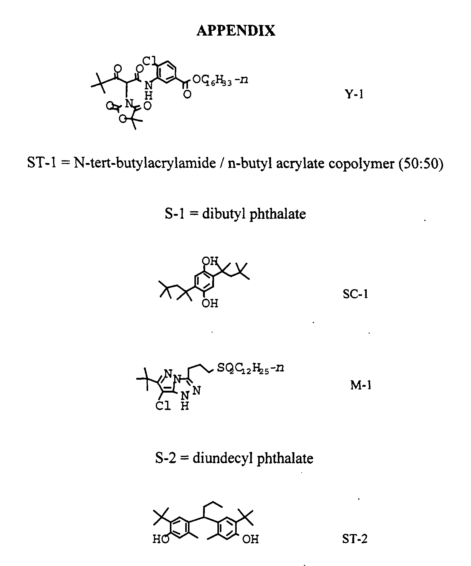
| | ST-1 | 440 |
| | S-1 | 190 |
| Layer 2 | Interlayer |
| | Gelatin | 650 |
| | SC-1 | 55 |
| | S-1 | 160 |
| Layer 3 | Green Sensitive Layer |
| | Gelatin | 1100 |
| | Green sensitive silver (Green EM-1) | 70 |
| | M-1 | 270 |
| | S-1 | 75 |
| | S-2 | 32 |
| | ST-2 | 20 |
| | ST-3 | 165 |
| | ST-4 | 530 |
| Layer 4 | UV Interlayer |
| | Gelatin | 635 |
| | UV-1 | 30 |
| | UV-2 | 160 |
| | SC-1 | 50 |
| | S-3 | 30 |
| | S-1 | 30 |
| Layer 5 | Red Sensitive Layer |
| | Gelatin | 1200 |
| | Red sensitive silver | 170 |
| | C-1 | 365 |
| | S-1 | 360 |
| | UV-2 | 235 |
| | S-4 | 30 |
| | SC-1 | 3 |
| Layer 6 | UV Overcoat |
| | Gelatin | 440 |
| | UV-1 | 20 |
| | UV-2 | 110 |
| | SC-1 | 30 |
| | S-3 | 20 |
| | S-1 | 20 |
| Layer 7 | SOC |
| | Gelatin | 490 |
| | SC-1 | 17 |
| | SiO2 | 200 |
| | Surfactant | 2 |