EP1130453A2 - Polarization control device - Google Patents
Polarization control device Download PDFInfo
- Publication number
- EP1130453A2 EP1130453A2 EP00123546A EP00123546A EP1130453A2 EP 1130453 A2 EP1130453 A2 EP 1130453A2 EP 00123546 A EP00123546 A EP 00123546A EP 00123546 A EP00123546 A EP 00123546A EP 1130453 A2 EP1130453 A2 EP 1130453A2
- Authority
- EP
- European Patent Office
- Prior art keywords
- liquid crystal
- electrodes
- crystal material
- electrical field
- light
- Prior art date
- Legal status (The legal status is an assumption and is not a legal conclusion. Google has not performed a legal analysis and makes no representation as to the accuracy of the status listed.)
- Withdrawn
Links
- 230000010287 polarization Effects 0.000 title claims abstract description 70
- 239000004973 liquid crystal related substance Substances 0.000 claims abstract description 125
- 239000000463 material Substances 0.000 claims abstract description 71
- 230000005684 electric field Effects 0.000 claims abstract description 58
- 230000003287 optical effect Effects 0.000 claims abstract description 18
- 230000007935 neutral effect Effects 0.000 claims abstract description 11
- 230000008859 change Effects 0.000 claims abstract description 9
- 239000013307 optical fiber Substances 0.000 claims description 18
- 239000013598 vector Substances 0.000 claims description 18
- 238000000034 method Methods 0.000 claims description 5
- 230000001419 dependent effect Effects 0.000 claims description 3
- 210000002858 crystal cell Anatomy 0.000 description 25
- 239000006059 cover glass Substances 0.000 description 15
- 238000010586 diagram Methods 0.000 description 14
- 239000000835 fiber Substances 0.000 description 9
- 239000012071 phase Substances 0.000 description 8
- 230000010363 phase shift Effects 0.000 description 6
- 230000009466 transformation Effects 0.000 description 6
- 210000004027 cell Anatomy 0.000 description 4
- 230000004044 response Effects 0.000 description 4
- 238000004891 communication Methods 0.000 description 3
- 239000004642 Polyimide Substances 0.000 description 2
- 241000566604 Sturnella Species 0.000 description 2
- 238000000576 coating method Methods 0.000 description 2
- 230000000694 effects Effects 0.000 description 2
- 239000011521 glass Substances 0.000 description 2
- 238000012986 modification Methods 0.000 description 2
- 230000004048 modification Effects 0.000 description 2
- 229920001721 polyimide Polymers 0.000 description 2
- 239000007787 solid Substances 0.000 description 2
- 239000000126 substance Substances 0.000 description 2
- 230000002411 adverse Effects 0.000 description 1
- 239000011248 coating agent Substances 0.000 description 1
- 239000013078 crystal Substances 0.000 description 1
- 238000001514 detection method Methods 0.000 description 1
- 238000010438 heat treatment Methods 0.000 description 1
- 230000001939 inductive effect Effects 0.000 description 1
- 238000007689 inspection Methods 0.000 description 1
- 230000003993 interaction Effects 0.000 description 1
- 239000007788 liquid Substances 0.000 description 1
- 239000007791 liquid phase Substances 0.000 description 1
- 238000005259 measurement Methods 0.000 description 1
- 230000001902 propagating effect Effects 0.000 description 1
- 238000000926 separation method Methods 0.000 description 1
- 238000007493 shaping process Methods 0.000 description 1
- 238000012360 testing method Methods 0.000 description 1
- 230000007704 transition Effects 0.000 description 1
Images



Classifications
-
- G—PHYSICS
- G02—OPTICS
- G02F—OPTICAL DEVICES OR ARRANGEMENTS FOR THE CONTROL OF LIGHT BY MODIFICATION OF THE OPTICAL PROPERTIES OF THE MEDIA OF THE ELEMENTS INVOLVED THEREIN; NON-LINEAR OPTICS; FREQUENCY-CHANGING OF LIGHT; OPTICAL LOGIC ELEMENTS; OPTICAL ANALOGUE/DIGITAL CONVERTERS
- G02F1/00—Devices or arrangements for the control of the intensity, colour, phase, polarisation or direction of light arriving from an independent light source, e.g. switching, gating or modulating; Non-linear optics
- G02F1/01—Devices or arrangements for the control of the intensity, colour, phase, polarisation or direction of light arriving from an independent light source, e.g. switching, gating or modulating; Non-linear optics for the control of the intensity, phase, polarisation or colour
- G02F1/13—Devices or arrangements for the control of the intensity, colour, phase, polarisation or direction of light arriving from an independent light source, e.g. switching, gating or modulating; Non-linear optics for the control of the intensity, phase, polarisation or colour based on liquid crystals, e.g. single liquid crystal display cells
- G02F1/1326—Liquid crystal optical waveguides or liquid crystal cells specially adapted for gating or modulating between optical waveguides
-
- G—PHYSICS
- G02—OPTICS
- G02F—OPTICAL DEVICES OR ARRANGEMENTS FOR THE CONTROL OF LIGHT BY MODIFICATION OF THE OPTICAL PROPERTIES OF THE MEDIA OF THE ELEMENTS INVOLVED THEREIN; NON-LINEAR OPTICS; FREQUENCY-CHANGING OF LIGHT; OPTICAL LOGIC ELEMENTS; OPTICAL ANALOGUE/DIGITAL CONVERTERS
- G02F1/00—Devices or arrangements for the control of the intensity, colour, phase, polarisation or direction of light arriving from an independent light source, e.g. switching, gating or modulating; Non-linear optics
- G02F1/01—Devices or arrangements for the control of the intensity, colour, phase, polarisation or direction of light arriving from an independent light source, e.g. switching, gating or modulating; Non-linear optics for the control of the intensity, phase, polarisation or colour
- G02F1/0136—Devices or arrangements for the control of the intensity, colour, phase, polarisation or direction of light arriving from an independent light source, e.g. switching, gating or modulating; Non-linear optics for the control of the intensity, phase, polarisation or colour for the control of polarisation, e.g. state of polarisation [SOP] control, polarisation scrambling, TE-TM mode conversion or separation
-
- G—PHYSICS
- G02—OPTICS
- G02F—OPTICAL DEVICES OR ARRANGEMENTS FOR THE CONTROL OF LIGHT BY MODIFICATION OF THE OPTICAL PROPERTIES OF THE MEDIA OF THE ELEMENTS INVOLVED THEREIN; NON-LINEAR OPTICS; FREQUENCY-CHANGING OF LIGHT; OPTICAL LOGIC ELEMENTS; OPTICAL ANALOGUE/DIGITAL CONVERTERS
- G02F1/00—Devices or arrangements for the control of the intensity, colour, phase, polarisation or direction of light arriving from an independent light source, e.g. switching, gating or modulating; Non-linear optics
- G02F1/01—Devices or arrangements for the control of the intensity, colour, phase, polarisation or direction of light arriving from an independent light source, e.g. switching, gating or modulating; Non-linear optics for the control of the intensity, phase, polarisation or colour
- G02F1/13—Devices or arrangements for the control of the intensity, colour, phase, polarisation or direction of light arriving from an independent light source, e.g. switching, gating or modulating; Non-linear optics for the control of the intensity, phase, polarisation or colour based on liquid crystals, e.g. single liquid crystal display cells
- G02F1/133—Constructional arrangements; Operation of liquid crystal cells; Circuit arrangements
- G02F1/1333—Constructional arrangements; Manufacturing methods
- G02F1/1343—Electrodes
- G02F1/134309—Electrodes characterised by their geometrical arrangement
- G02F1/134363—Electrodes characterised by their geometrical arrangement for applying an electric field parallel to the substrate, i.e. in-plane switching [IPS]
-
- G—PHYSICS
- G02—OPTICS
- G02F—OPTICAL DEVICES OR ARRANGEMENTS FOR THE CONTROL OF LIGHT BY MODIFICATION OF THE OPTICAL PROPERTIES OF THE MEDIA OF THE ELEMENTS INVOLVED THEREIN; NON-LINEAR OPTICS; FREQUENCY-CHANGING OF LIGHT; OPTICAL LOGIC ELEMENTS; OPTICAL ANALOGUE/DIGITAL CONVERTERS
- G02F1/00—Devices or arrangements for the control of the intensity, colour, phase, polarisation or direction of light arriving from an independent light source, e.g. switching, gating or modulating; Non-linear optics
- G02F1/01—Devices or arrangements for the control of the intensity, colour, phase, polarisation or direction of light arriving from an independent light source, e.g. switching, gating or modulating; Non-linear optics for the control of the intensity, phase, polarisation or colour
- G02F1/13—Devices or arrangements for the control of the intensity, colour, phase, polarisation or direction of light arriving from an independent light source, e.g. switching, gating or modulating; Non-linear optics for the control of the intensity, phase, polarisation or colour based on liquid crystals, e.g. single liquid crystal display cells
- G02F1/137—Devices or arrangements for the control of the intensity, colour, phase, polarisation or direction of light arriving from an independent light source, e.g. switching, gating or modulating; Non-linear optics for the control of the intensity, phase, polarisation or colour based on liquid crystals, e.g. single liquid crystal display cells characterised by the electro-optical or magneto-optical effect, e.g. field-induced phase transition, orientation effect, guest-host interaction or dynamic scattering
- G02F1/139—Devices or arrangements for the control of the intensity, colour, phase, polarisation or direction of light arriving from an independent light source, e.g. switching, gating or modulating; Non-linear optics for the control of the intensity, phase, polarisation or colour based on liquid crystals, e.g. single liquid crystal display cells characterised by the electro-optical or magneto-optical effect, e.g. field-induced phase transition, orientation effect, guest-host interaction or dynamic scattering based on orientation effects in which the liquid crystal remains transparent
- G02F1/1393—Devices or arrangements for the control of the intensity, colour, phase, polarisation or direction of light arriving from an independent light source, e.g. switching, gating or modulating; Non-linear optics for the control of the intensity, phase, polarisation or colour based on liquid crystals, e.g. single liquid crystal display cells characterised by the electro-optical or magneto-optical effect, e.g. field-induced phase transition, orientation effect, guest-host interaction or dynamic scattering based on orientation effects in which the liquid crystal remains transparent the birefringence of the liquid crystal being electrically controlled, e.g. ECB-, DAP-, HAN-, PI-LC cells
Definitions
- the present invention relates generally to devices for controlling light characteristics in an optical communication system, and more particularly, to devices that control the state of polarization of light in an optical communication system.
- Devices that control the state of polarization of light find application in fiber optical communication systems, as well as in optical test and measurement equipment. Most of the devices for controlling the polarization state of light are operated manually by turning an optical fiber or other optical element, or are operated by using the electrode-optic effect in solid state devices. These polarization control devices are typically able to convert any input state of polarization to any output state of polarization. However, mechanical polarization control devices have a slow response time on the order of 1000 ms, and have large dimensions (typically several 10 cm 3 ), and consume more than 100 mW of power to drive the motors that provide the necessary movement of optical elements.
- Another method for controlling the state of polarization of light is to use a liquid crystal-based polarization controller.
- Such controllers allow the transformation from any input state of polarization to a limited range of output states of polarization.
- one such polarization control device is made by Meadowlark Corporation, Frederick, Colorado, and uses a series of liquid crystal wave plates at fixed orientations with variable retardance to form a polarization control device.
- the Meadowlark device uses a modulating electric field which is perpendicular to the boundary planes of the liquid crystal device.
- a problem of Meadowlark-type devices is that they are not able to convert any input state polarization to any output state of polarization. Additionally, this type of device also has a relatively large power requirement as well as a large response time.
- the present invention comprises, in one embodiment, a polarization control device, comprising: a liquid crystal device containing a liquid crystal material with an optical anisotropy with substantially homeotropically aligned molecules when in a neutral electrical field state; a plurality of electrodes for applying an electrical field to change an orientation of the molecules of the liquid crystal material from their alignment in the neutral electrical field state; a circuit for applying a voltage to the electrodes; and an optical system for directing light through the liquid crystal material.
- the liquid crystal device includes two parallel alignment plates with the liquid crystal material disposed therebetween; and wherein the electrodes comprise at least one electrode disposed adjacent one of the alignment plates on one side of the directed light, and at least another of the electrodes disposed adjacent the other of the alignment plates on an opposite side of the directed light, and energized to generate an electrical field substantially parallel to the alignment plates, but with an electrical field component perpendicular to the alignment plate.
- a polarization detector is included that is disposed to receive light transmitted through the liquid crystal material and to generate a signal dependent on the polarization of the light received from the liquid crystal material; and a feedback circuit for receiving the polarization-dependent signal, generating a control signal, and providing that control signal to the circuit for applying a voltage to the electrodes, to control a voltage characteristic of the electrodes in accordance therewith.
- a method for polarization control comprising the steps of: providing a liquid crystal device that contains a liquid crystal material with homeotropically aligned molecules when in a neutral state; causing an electrical field to be generated across the liquid crystal device; and directing light through the liquid crystal material.
- the present invention is directed to a polarization control device based on a liquid crystal cell.
- the invention allows the transformation of substantially any input state of polarization to substantially any output state of polarization with a low power consumption in the control device.
- the power consumption may be less than 1 mW, with a response time in the range of 10 ms. Additionally, the size and price of the present inventive embodiment is significantly lower than for other solutions.
- a liquid crystal cell 10 which may be utilized to implement the present invention is shown in Fig. 2A.
- the embodiment disclosed includes cover glasses 11 and 12, electrodes 14 and 16 which are connected by lines and circuitry 17 to appropriate voltages, alignment layers 18 and 20, and liquid crystal material 22.
- the cover glasses 10 and 12 are preferably parallel to provide a uniform cell gap for the device.
- the electrical field applied controls the orientation of the anisotropy of the liquid crystal.
- the gap across the cover glasses 10 and 12 must typically be thick enough to provide a sufficient amount of phase shift. By way of example, the gap typically will be in the range of one to ten microns.
- the preferred thickness/gap is determined based on the optical anisotropy of the material 22 used for the liquid crystal.
- the liquid crystal material 22 is preferably uniaxially birefringent.
- the refractive index for the liquid crystal material 22 can be described as an ellipsoid.
- the liquid crystal material 22 may be implemented by a variety of materials including nematic phase liquid crystal materials and other materials with liquid crystal phases that allow for a similar alignment of the crystal orientation that is initially perpendicular to the cover glass boundaries.
- a typical example of such a liquid crystal material that provides a positive dielectric anisotropy is made by Merck, Whitehouse Station, New Jersey and designated with product names Merck ZLI-4792 and MLC13300-000.
- the electrodes 14 and 16 are formed by coating selected areas on the glass covers 11 and 12 with an appropriate material which is electrically conducting. Note that the drawing does not illustrate the coatings, but rather shows the electrodes as separate elements for ease of explanation.
- the alignment layers 18 and 20 are used to induce the liquid crystal molecules therebetween to orient themselves in a particular direction.
- the alignment layers are chosen so that without an electric field being applied, the orientation of the long axis of the ellipsoid of the liquid crystal material 22 is perpendicular to the cover glass plates 11 and 12.
- the particular material used to implement the alignment layers 18 and 20 will depend on the particular liquid crystal material 22 being utilized.
- the alignment layers 18 and 20 preferentially force the liquid crystal molecules that come in contact with the surface thereof to orient in a particular direction. In the present invention, this particular direction is a homeotropic orientation, meaning that the long axis of the liquid crystal molecules are substantially perpendicular to the plane of the alignment layers 18 and 20.
- the material for these alignment layers 18 and 20 may be polyimide which is available from a variety of companies including DuPont, EM, and Nissan Chemical. Specific examples of such material are SE7511L and SE2511L from Nissan Chemical America Corporation, Houston, Texas.
- the alignment layers may be deposited over the cover glasses 11 and 12 and the electrodes 14 and 16.
- the initial homeotropic alignment which is desired for the present invention is accomplished by the interaction between the liquid crystal material 22 and the molecules of the polyimide alignment layers 18 and 20 deposited on the cover glass. Light is to be directed through the liquid crystal material 22 in the direction of the arrow 24.
- Incoming light 30 may be delivered to a lens system 32.
- the light may be delivered to the lens system through a variety of different delivery media.
- the light may be delivered by means of an optical fiber 30.
- the lens system 32 is shown to be a collimating lens 32, which operates to collimate the light received into a substantially parallel beam of light 34.
- the collimated light 34 is directed through the liquid crystal material 22 in the liquid crystal cell 10 and then focused by a focusing lens 36 back into an optical fiber 38.
- An electrical voltage supplied to the electrodes 14 and 16 in the liquid crystal cell 10 causes an electrical field (shown in Fig. 2B) to be directed through the liquid crystal material 22 to thereby induce an electrical dipole in the liquid crystal molecules to change the orientation of the liquid crystal material 22.
- this change in the orientation of the liquid crystal material changes the state of polarization of the light passing through the liquid crystal material 22.
- a liquid crystal material 22 is utilized in the liquid crystal cell 10 that allows for fast changes in orientation of the liquid crystal material. It should be noted that even faster changes in orientation of the liquid crystal material can be achieved by heating the liquid crystal material.
- the temperature change required will depend on the liquid crystal material chosen, and the highest temperature must be below the nematic isotropic phase transition.
- the nematic phase is one of the liquid phases between liquid and solid and depends on the choice of material.
- neutral electrical field state means the field necessary to achieve a homeotropic alignment of the liquid crystal molecules. In most cases, this neutral electrical field state is a 0 volt electrical field.
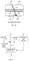
- a schematic cross sectional diagram is shown of the liquid crystal cell 10 with a voltage applied to the electrodes 14 and 16 to thereby apply an electrical field to the liquid crystal material 22.
- the electrical field should have a small vector component parallel to the original orientation (the original orientation is substantially perpendicular to the planes of the cover glasses 11 and 12) of the refractive index ellipse of the liquid crystal molecules in order to define a sense of rotation for the liquid crystal molecules as the electrical field across the electrodes 14 and 16 is increased.
- the present invention is not limited to any particular type of voltage, and both direct current and alternating current voltages may be applied, it is preferred that an AC voltage or other symmetrical waveform voltage be utilized in order to prevent charges from migrating in the liquid crystal material 22. It should be noted that if the electrical field being applied does not have a small vector component parallel to the original orientation of the refractive index ellipse of the liquid crystal molecules, then when the AC voltage is applied, since there is no preferred direction of rotation for the liquid crystal molecules, domain boundaries may be set up in the material 22 that would cause adverse effects on the performance of the polarization control.
- an electrode structure is used that provides at least a pair of electrodes, with one electrode 14 in the pair of electrodes disposed on a surface of the cover glass 11, and the other electrode 16 in the pair of electrodes disposed on a surface of the cover glass 12, but at an opposite end of the cover glass 12 relative to the location of the electrode 14 on the cover glass 11, so that the electrodes 14 and 16 straddle and are on opposite sides of the beam of light 24 propagating through the liquid crystal material 22, as shown in Fig. 2A and Fig. 2B.
- This asymmetry provides a small component of the electrical field perpendicular to the plane of the alignment layers or plates 18 and 20.
- the angle ⁇ between the direction of the electrical field generated by the electrodes 14 and 16 and the x axis, and which is shown in Fig. 2B, is significantly exaggerated for purposes of illustration.
- the dimension of the liquid crystal cell 10 in the y direction is significantly longer than the dimension in the x direction between the cover glass plates 11 and 12, so that the component of the electrical field which is parallel to the original substantially horizontal (parallel to the x axis) orientation of the liquid crystal molecules refractive index ellipse is small relative to the electrical field component perpendicular to this original orientation.
- the cell electrodes 14 and 16 are preferably be shaped in a way to avoid overlap with the path of the optical beam 24 through the liquid crystal cell 10. Properly shaped electrodes 14 and 16 will minimize optical loss and reflection. It should also be noted that the placement and shape of the electrodes 14 and 16 control the uniformity of the electrical field over a given area. Accordingly, a variety of different electrode pair placements and shapes may be utilized in order to achieve a desired level of uniformity of the electrical field. Moreover, multiple electrode pairs may be utilized to achieve desired levels of electrical field uniformity. By way of example, a desired electrical field uniformity may be 0.1% over a particular area of the liquid crystal material.
- the optical system 32 used to direct the light through the liquid crystal material 22 can be optimized to direct the light through substantially only the area of uniform electrical field.
- an AC electrical field is applied to drive the liquid crystal cell 10 with a frequency high enough that the liquid crystal material responds only to the RMS value of the field.
- the preferred frequency range for the AC electric voltage is 1 kHz-10 kHz. However, the actual frequency for the AC voltage will depend on the LC material chosen.
- FIG. 3 one configuration of the electrodes 14 and 16 is shown.
- the voltages V1 and V2 are applied to spoke-shaped electrodes 14a and 14b, respectively, which are disposed at right angles on the cover glass 11.
- voltages-V1 and -V2 are applied to the spoke-shaped electrodes 16a and 16b, respectively, which are disposed at right angles on the cover glass 12, and make up the other end of the pairings for the electrodes 14a and 14b, respectively.
- This configuration of electrodes results in an electrical field that is tilted with respect to the initial refractive index ellipse of the liquid crystal molecules. The direction of the liquid crystal molecules is changed by the field.
- the ratio of the voltage amplitude V2/V1 determines the azimuthal orientation of the liquid crystal molecules, whereas the absolute voltage values determine the tilt from the original perpendicular orientation of the liquid crystal molecules.
- the tilt angle together with the birefringence of the liquid crystal molecules and the cell gap for the liquid crystal cell 10 determine the phase shift that is imposed on the optical beam 34 passing through the cell.
- the number of electrode pairs may be increased beyond the number shown to increase the uniformity of the electrical field at the location where the light beam 24 will pass through the liquid crystal device. Only two electrode pairs, 14a-16a and 14b-16b, are shown in Fig. 3 for convenience of illustration.
- an optical birefringent element in accordance with the present invention that can assume azimuthal orientations of, for example, 0 to 180°, and provide a phase shift also between 0 and 180°, thereby converting any input state of polarization to any output state of polarization.
- Fig. 1B and Fig. 1C Other possible embodiments for the lens system used with the liquid crystal polarization control device are shown in Fig. 1B and Fig. 1C.
- the lens systems control the shaping of the light beam as it is directed through the liquid crystal material 22 in order to be compatible with the area of electrical field uniformity.
- Fig. 1B only a single lens 40 is used, instead of two lenses, to focus light emitted from a fiber 30 into the second fiber 38, with the liquid crystal cell 10 located in the light path 34 between the lens 40 and the fiber 38, but closer to the fiber 38 than to the lens 40.
- the area of the light beam directed by a lens 40 onto the liquid crystal cell 10 may be controlled to be less than the area for the collimated beam of light shown in Fig. 1A, depending on the placement of the liquid crystal cell.
- a lens configuration is used with the liquid crystal cell 10 in order to focus the beam of light onto a very small area on the liquid crystal cell 10.
- the light is focused by a focusing lens 50 onto a very small area on the liquid crystal cell 10, and the light passing through the liquid crystal cell 10 is received by a lens 52 and focused onto the optical fiber 38.
- the configurations set forth in Fig. 1B and Fig. 1C are advantageous in that they allow for smaller liquid crystal cell dimensions and/or less complicated electrode configurations because a uniform electrical field must be achieved over a smaller area.
- Fig. 4 illustrates an alternative embodiment for the present invention.
- polarization control is accomplished using a section of hollow-core optical fiber 60, filled with liquid crystal material 62, and including a plurality of electrodes disposed to provide an electrical field.
- Figs. 5A, 58 and 5C illustrate the use of four electrode pairs.
- a first electrode pair 64a-64b provides an electrical field in a first direction 80, which is illustrated with the field lines between the electrodes 64a and 64b in Fig. 5B.
- a field perpendicular to that shown may be applied between electrodes 68a and electrode 68b, as shown in Fig. 5C.
- a second set of electrodes 70a and 70b may be provided to generate an electrical field in a different direction relative to the direction 80.
- an electrode pair 66a and 66b may be provided in order to generate an electrical field with a direction different from the electrical field provided by the electrode pair 68a - 68b.
- the long axis of the refractive index ellipse of the liquid crystal material 62 is initially aligned parallel to the direction of the fiber 60.
- a voltage is applied to the electrodes in a way to provide an electric field with a substantial vector component perpendicular to the direction of the fiber, and a small vector component parallel to the direction of the fiber for the reasons discussed previously.
- the operation of this fiber-based polarization control device is analogous to the previously described operation.
- the advantages of this optical fiber polarization control configuration are reduced size and fewer components in the system.
- a polarization control system with feedback there is shown a polarization control system with feedback. All of the elements in the system are not shown, for ease of illustration.
- the elements shown in the figure include a liquid crystal cell 10, a polarization state detector 90, and a feedback driver control circuit 96.
- light 92 with a first state of polarization enters the polarization control module that includes the liquid crystal cell 10 with the appropriate electrical drivers to provide the necessary electric field across electrodes on the liquid crystal cell 10, as previously described.
- the polarization control system changes the polarization state of the light 92 to a second state of polarization 94.
- This light 94 is detected by a polarization state detector 90 which provides an electrical feedback signal indicative of this detected polarization to the feedback driver control circuit 96 for use in generating a control signal to control the voltages across the electrodes to thereby set the liquid crystal cell 10 to the second state of polarization.
- the polarization state detector 90 can be implemented in a variety of different configurations.
- the polarization state detector 90 can include a beam splitter that transmits most of the light, but uses a fraction of the light for polarization state detection.
- One type of polarization state detector is made by Hewlett Packard Company, Palo Alto, California.
- This polarization state detector 90 in one embodiment, would generate at least three electrical signals (proportional to the Stokes parameters to thereby define a vector) that characterize the second state of polarization.
- the electrical signals proportional to the Stokes parameters for the second state of polarization are applied to the feedback driver control circuit 96 where they are compared to electrical signals proportional to the Stokes parameters for a vector representing a desired state of polarization. The difference generated by this comparison is used to control the ratio and the magnitudes of the voltages applied to the various electrode pairs in the liquid crystal cell 10 to achieve the desired polarization state.
- a state of complete polarization can be specified by a point on the surface of a Poincaré sphere as shown in Figure 7.
- Both a and s are normalized vectors, and a x and a y are positive numbers.
- the relative phase of the x and y components of the polarization are determined by the phase ⁇ , and the overall phase of a is not material to the representation of the state of polarization of the system.
- a birefringent plate having its slow axis in the ( x , y ) plane oriented at an angle ⁇ with respect to the x axis and inducing a relative phase shift of ⁇ between light polarized parallel to and perpendicular to the slow axis transforms states of polarization on the Poincarè sphere by a rotation of ⁇ about an axis in the ( i , j ) plane oriented at an angle of 2 ⁇ with respect to the i axis.
- any two points on a latitude of a sphere can be transformed into one another by a rotation about the pole to which that latitude is referenced. That latitude is defined by the intersection with the surface of the sphere of a plane perpendicular to the pole.
- the problem becomes finding a "pole" (i.e., a radial vector) that lies in the ( i , j ) plane and has a plane perpendicular to it that contains the two points on the Poincarè sphere representing the two states that are to be connected.
- the direction of that radius then defines the orientation of the slow axis of the birefringment plate required for the appropriate transformation, and the longitudinal angular separation of the two points (referenced to the "pole" defined by that radius) defines the required retardation of the plate.
Landscapes
- Physics & Mathematics (AREA)
- Nonlinear Science (AREA)
- General Physics & Mathematics (AREA)
- Optics & Photonics (AREA)
- Chemical & Material Sciences (AREA)
- Crystallography & Structural Chemistry (AREA)
- Geometry (AREA)
- Mathematical Physics (AREA)
- Liquid Crystal (AREA)
Abstract
Description

Claims (21)
- A polarization control device, comprising:a liquid crystal device (10) containing a liquid crystal material (22,62) with an optical anisotropy with substantially homeotropically aligned molecules when in a neutral electrical field state;a plurality of electrodes (14, 16, 64a, 64b, 66a, 66b, 68a, 68b, 70a, 70b) for applying an electrical field to change an orientation of the molecules of said liquid crystal material from their alignment in the neutral electrical field state;a circuit (17, 96) for applying a voltage to said electrodes; andan optical system (30, 32, 40, 50, for directing light through said liquid crystal material.
- A device as defined in claim 1, wherein said electrodes comprise at least one pair of electrodes shaped to substantially avoid overlap with said directed light and disposed on different sides of said directed light.
- A device as defined in claim 1, wherein said electrodes comprise at least one pair of spoke electrodes (14a, 14b, 16a, 16b) disposed on different sides of said directed light.
- A device as defined in claim 1, 2 or 3, wherein said liquid crystal device includes an alignment plate (18, 20) that aligns said molecules; and wherein said electrodes generate an electrical field substantially parallel to said alignment plate, but with an electrical field component perpendicular to said alignment plate.
- A device as defined in claim 1, 2 or 3, wherein said liquid crystal device includes two parallel alignment plates with said liquid crystal material disposed therebetween; and
wherein said electrodes comprise at least one electrode disposed adjacent one of said alignment plates on one side of said directed light, and at least another of said electrodes disposed adjacent the other of said alignment plates on an opposite side of said alignment plates, but with an electrical field component perpendicular to said alignment plate. - A device as defined in claim 5, wherein said electrodes comprise a plurality of pairs of electrodes, with each pair of electrodes at a different orientation around and on opposite sides of said directed light.
- A device as defined in one of the preceding claims, wherein said opticial system is an optical fiber.
- A device as defined in one of the preceding claims, wherein said electrodes are positioned to cause a vector component of said electrical field to be parallel to a homeotropic orientation of said homeotropically aligned molecules of said liquid crystal material when in a neutral electrical field state.
- A device as defined in one of the preceding claims, wherein said voltage applying circuit provides a voltage to said electrodes at a frequency so that said liquid crystal material responds only to an RMS value of said voltage.
- A device as defined in one of claims 1 - 6, wherein said opticial system comprises:an optical fiber; anda lens for directing light from said optical fiber to said liquid crystal material.
- A device as defined in claim 10, wherein said lens is designed to collimate light from said optical fiber and direct that collimated light onto said liquid crystal material.
- A device as defined in claim 10, wherein said lens is designed to focus light from said optical fiber onto said liquid crystal material.
- A device as defined in claim 10, wherein said lens is designed to focus said light to a predetermined area on said liquid crystal device.
- A device as defined in claim 1, further comprising:a polarization detector disposed to receive light transmitted through said liquid crystal material and generating a vector signal dependent on polarization of the light received from said liquid crystal material; anda feedback circuit for receiving said vector signal, generating a control signal, and providing said control signal to said circuit for applying a voltage to said electrodes, to control a voltage characteristic of said electrodes in accordance therewith.
- A device as defined in claim 14, wherein said electrodes comprise at least two pairs of electrodes; and wherein said feedback circuit controls a ratio of the voltages applied across said pairs of electrodes.
- A device as defined in claim 10, wherein said lens does not collimate said light or focus said light on said liquid crystal material.
- A device as defined in claim 1, wherein said liquid crystal device comprises a hollow-core optical fiber; and wherein said liquid crystal material is disposed within a hollow interior of said hollow core optical fiber.
- A device as defined in claim 17, wherein said electrodes comprise at least the pairs of electrodes disposed on opposite sides of said hollow-core optical fiber.
- A device as defined in one of the preceding claims, further comprising a heater disposed to heat said liquid crystal material.
- A method for polarization control comprising the steps of:providing a liquid crystal device that contains a liquid crystal material with homeotropically aligned molecules when in a neutral state;causing an electrical field to be generated across said liquid crystal device; anddirecting light through said liquid crystal material.
- A method as defined in claim 20, wherein said electrical field causing step comprises the step of generating an electrical field substantially parallel to an alignment plate in said liquid crystal device, but with an electrical field component perpendicular to said alignment plate.
Applications Claiming Priority (2)
| Application Number | Priority Date | Filing Date | Title |
|---|---|---|---|
| US502362 | 2000-02-29 | ||
| US09/502,362 US6686984B1 (en) | 2000-02-29 | 2000-02-29 | Polarization control device |
Publications (2)
| Publication Number | Publication Date |
|---|---|
| EP1130453A2 true EP1130453A2 (en) | 2001-09-05 |
| EP1130453A3 EP1130453A3 (en) | 2003-03-19 |
Family
ID=23997462
Family Applications (1)
| Application Number | Title | Priority Date | Filing Date |
|---|---|---|---|
| EP00123546A Withdrawn EP1130453A3 (en) | 2000-02-29 | 2000-10-27 | Polarization control device |
Country Status (3)
| Country | Link |
|---|---|
| US (1) | US6686984B1 (en) |
| EP (1) | EP1130453A3 (en) |
| JP (1) | JP2001264821A (en) |
Cited By (2)
| Publication number | Priority date | Publication date | Assignee | Title |
|---|---|---|---|---|
| FR2841003A1 (en) * | 2002-06-14 | 2003-12-19 | Thales Sa | BINDING-FREE POLARIZATION CONTROL SYSTEM IN AN OPTICAL LINK |
| CN100389340C (en) * | 2006-04-14 | 2008-05-21 | 北京高光科技有限公司 | Device and method capable of quantitatively adjusting the polarization state of light |
Families Citing this family (6)
| Publication number | Priority date | Publication date | Assignee | Title |
|---|---|---|---|---|
| US20030214713A1 (en) * | 2001-12-21 | 2003-11-20 | Edward Collett | Method and device to calculate and display the transformation of optical polarization states |
| US7974510B2 (en) * | 2003-05-29 | 2011-07-05 | Agilent Technologies, Inc. | Optical waveguide having a core with a polarization-independent, spatially reconfigurable refractive index |
| JP4370829B2 (en) * | 2003-06-30 | 2009-11-25 | 旭硝子株式会社 | Polarization control element |
| JP4204970B2 (en) * | 2003-12-25 | 2009-01-07 | 日本電信電話株式会社 | Polarization control element and driving method thereof |
| JP5852956B2 (en) * | 2009-06-23 | 2016-02-03 | シーリアル テクノロジーズ ソシエテ アノニムSeereal Technologies S.A. | Light modulation device used for at least one of two-dimensional and three-dimensional image content display |
| CN117607038A (en) * | 2023-10-13 | 2024-02-27 | 北京航空航天大学 | A polarization state detection system based on layered two-dimensional nano-liquid crystal materials |
Family Cites Families (11)
| Publication number | Priority date | Publication date | Assignee | Title |
|---|---|---|---|---|
| GB8621438D0 (en) * | 1986-09-05 | 1986-10-15 | Secr Defence | Electro-optic device |
| GB8703795D0 (en) * | 1987-02-18 | 1987-03-25 | Gen Electric Co Plc | Polarisation controller |
| US5111321A (en) * | 1990-10-16 | 1992-05-05 | Bell Communications Research, Inc. | Dual-polarization liquid-crystal etalon filter |
| GB2255193B (en) | 1991-04-24 | 1994-10-12 | Marconi Gec Ltd | Optical device |
| US5361320A (en) * | 1993-02-19 | 1994-11-01 | University Of Colorado Foundation | Liquid crystal fiber waveguide |
| US5532854A (en) * | 1994-01-25 | 1996-07-02 | Fergason; James L. | Folded variable birefringerence zeroth order hybrid aligned liquid crystal apparatus |
| US5859728A (en) | 1994-10-24 | 1999-01-12 | The United States Of America As Represented By The Administrator Of The National Aeronautics And Space Administration | Method and apparatus for improved spatial light modulation |
| US6154591A (en) * | 1998-04-20 | 2000-11-28 | British Telecommunications Public Limited Company | Tunable optical device |
| JP4364332B2 (en) * | 1998-06-23 | 2009-11-18 | シャープ株式会社 | Liquid crystal display |
| US6404537B1 (en) * | 2000-03-06 | 2002-06-11 | Corning Applied Technologies Corporation | Polarization transformer |
| US6373614B1 (en) * | 2000-08-31 | 2002-04-16 | Cambridge Research Instrumentation Inc. | High performance polarization controller and polarization sensor |
-
2000
- 2000-02-29 US US09/502,362 patent/US6686984B1/en not_active Expired - Fee Related
- 2000-10-27 EP EP00123546A patent/EP1130453A3/en not_active Withdrawn
-
2001
- 2001-02-20 JP JP2001043573A patent/JP2001264821A/en active Pending
Cited By (3)
| Publication number | Priority date | Publication date | Assignee | Title |
|---|---|---|---|---|
| FR2841003A1 (en) * | 2002-06-14 | 2003-12-19 | Thales Sa | BINDING-FREE POLARIZATION CONTROL SYSTEM IN AN OPTICAL LINK |
| WO2003107080A1 (en) * | 2002-06-14 | 2003-12-24 | Thales | System for non-stop control of polarization in an optical link |
| CN100389340C (en) * | 2006-04-14 | 2008-05-21 | 北京高光科技有限公司 | Device and method capable of quantitatively adjusting the polarization state of light |
Also Published As
| Publication number | Publication date |
|---|---|
| US6686984B1 (en) | 2004-02-03 |
| EP1130453A3 (en) | 2003-03-19 |
| JP2001264821A (en) | 2001-09-26 |
Similar Documents
| Publication | Publication Date | Title |
|---|---|---|
| US4988169A (en) | Optical signal control method and apparatus | |
| US6778246B2 (en) | Liquid crystal adaptive lens with closed-loop electrodes and related fabrication methods and control methods | |
| EP2443487B1 (en) | Tunable electro-optic liquid crystal lens and method of forming the same | |
| US5313562A (en) | Optical device with electrodes end-to-end with electric field causing homeotropic alignment of liquid crystal in space between ends | |
| US20120242918A1 (en) | Cholesteric liquid crystal structure | |
| EP0302091B1 (en) | Polarisation controller | |
| Broughton et al. | Optimized flexoelectric response in a chiral liquid-crystal phase device | |
| KR100449352B1 (en) | Liquid crystal display device, compensation layer, and delayed-deadening method | |
| JP5190262B2 (en) | Device having controlled polarization state of output light, method of driving device, method of using cell in device, optical router, method of controlling or changing polarization state of light, and display device | |
| Xie et al. | Photonic spin Hall effect by electro-optically induced Pancharatnam-Berry phases | |
| US6686984B1 (en) | Polarization control device | |
| US4522468A (en) | Information display device having a liquid crystal cell | |
| Acharya et al. | In-fiber nematic liquid crystal optical modulator based on in-plane switching with microsecond response time | |
| US6765635B1 (en) | Apparatus and method for achromatic liquid crystal electro-optic modulation | |
| CN109031737A (en) | A kind of fast-response phase delay device based on the double-deck nematic liquid crystal | |
| Cheng et al. | Fast‐switchable polarization‐dependent bifocal lenses for AR displays | |
| US6895688B2 (en) | Liquid crystal polarization rotator and method of using same | |
| US7375889B1 (en) | Apparatus and method for controlling polarization in an optical communications medium | |
| Zhang et al. | Complete polarization controller based on magneto-optic crystals and fixed quarter wave plates | |
| Wang et al. | Origin of oblique optical axis of electrically tunable focusing lenses arising from initial anisotropic molecular tilts under a symmetric electric field. I | |
| Kang et al. | Liquid crystal microlens with dual apertures and electrically controlling focus shift | |
| Konshina et al. | Optical modulators based on a dual-frequency nematic liquid crystal | |
| Amosova et al. | Ways of increasing the response rate of electrically controlled optical devices based on nematic liquid crystals | |
| Gu et al. | Dual frequency liquid crystal devices for infrared electro-optical applications | |
| Nose et al. | Application of a liquid crystal microlens to an optical fiber switch |
Legal Events
| Date | Code | Title | Description |
|---|---|---|---|
| PUAI | Public reference made under article 153(3) epc to a published international application that has entered the european phase |
Free format text: ORIGINAL CODE: 0009012 |
|
| AK | Designated contracting states |
Kind code of ref document: A2 Designated state(s): AT BE CH CY DE DK ES FI FR GB GR IE IT LI LU MC NL PT SE |
|
| AX | Request for extension of the european patent |
Free format text: AL;LT;LV;MK;RO;SI |
|
| RAP1 | Party data changed (applicant data changed or rights of an application transferred) |
Owner name: AGILENT TECHNOLOGIES, INC. (A DELAWARE CORPORATION |
|
| PUAL | Search report despatched |
Free format text: ORIGINAL CODE: 0009013 |
|
| AK | Designated contracting states |
Kind code of ref document: A3 Designated state(s): AT BE CH CY DE DK ES FI FR GB GR IE IT LI LU MC NL PT SE Designated state(s): AT BE CH CY DE DK ES FI FR GB GR IE IT LI LU MC NL PT SE |
|
| AX | Request for extension of the european patent |
Extension state: AL LT LV MK RO SI |
|
| RIC1 | Information provided on ipc code assigned before grant |
Ipc: 7G 02F 1/1343 B Ipc: 7G 02F 1/139 B Ipc: 7G 02F 1/01 A |
|
| AKX | Designation fees paid | ||
| REG | Reference to a national code |
Ref country code: DE Ref legal event code: 8566 |
|
| STAA | Information on the status of an ep patent application or granted ep patent |
Free format text: STATUS: THE APPLICATION IS DEEMED TO BE WITHDRAWN |
|
| 18D | Application deemed to be withdrawn |
Effective date: 20030922 |