EP1130432A2 - Tunable optical add/drop filter and method - Google Patents
Tunable optical add/drop filter and method Download PDFInfo
- Publication number
- EP1130432A2 EP1130432A2 EP00307369A EP00307369A EP1130432A2 EP 1130432 A2 EP1130432 A2 EP 1130432A2 EP 00307369 A EP00307369 A EP 00307369A EP 00307369 A EP00307369 A EP 00307369A EP 1130432 A2 EP1130432 A2 EP 1130432A2
- Authority
- EP
- European Patent Office
- Prior art keywords
- wavelength
- filter
- optical
- region
- tunable
- Prior art date
- Legal status (The legal status is an assumption and is not a legal conclusion. Google has not performed a legal analysis and makes no representation as to the accuracy of the status listed.)
- Granted
Links
Images


Classifications
-
- G—PHYSICS
- G02—OPTICS
- G02B—OPTICAL ELEMENTS, SYSTEMS OR APPARATUS
- G02B6/00—Light guides; Structural details of arrangements comprising light guides and other optical elements, e.g. couplings
- G02B6/24—Coupling light guides
- G02B6/26—Optical coupling means
- G02B6/28—Optical coupling means having data bus means, i.e. plural waveguides interconnected and providing an inherently bidirectional system by mixing and splitting signals
- G02B6/293—Optical coupling means having data bus means, i.e. plural waveguides interconnected and providing an inherently bidirectional system by mixing and splitting signals with wavelength selective means
- G02B6/29346—Optical coupling means having data bus means, i.e. plural waveguides interconnected and providing an inherently bidirectional system by mixing and splitting signals with wavelength selective means operating by wave or beam interference
- G02B6/29358—Multiple beam interferometer external to a light guide, e.g. Fabry-Pérot, etalon, VIPA plate, OTDL plate, continuous interferometer, parallel plate resonator
-
- G—PHYSICS
- G01—MEASURING; TESTING
- G01J—MEASUREMENT OF INTENSITY, VELOCITY, SPECTRAL CONTENT, POLARISATION, PHASE OR PULSE CHARACTERISTICS OF INFRARED, VISIBLE OR ULTRAVIOLET LIGHT; COLORIMETRY; RADIATION PYROMETRY
- G01J3/00—Spectrometry; Spectrophotometry; Monochromators; Measuring colours
- G01J3/12—Generating the spectrum; Monochromators
- G01J3/26—Generating the spectrum; Monochromators using multiple reflection, e.g. Fabry-Perot interferometer, variable interference filters
-
- G—PHYSICS
- G02—OPTICS
- G02B—OPTICAL ELEMENTS, SYSTEMS OR APPARATUS
- G02B6/00—Light guides; Structural details of arrangements comprising light guides and other optical elements, e.g. couplings
- G02B6/24—Coupling light guides
- G02B6/26—Optical coupling means
- G02B6/28—Optical coupling means having data bus means, i.e. plural waveguides interconnected and providing an inherently bidirectional system by mixing and splitting signals
- G02B6/293—Optical coupling means having data bus means, i.e. plural waveguides interconnected and providing an inherently bidirectional system by mixing and splitting signals with wavelength selective means
- G02B6/29346—Optical coupling means having data bus means, i.e. plural waveguides interconnected and providing an inherently bidirectional system by mixing and splitting signals with wavelength selective means operating by wave or beam interference
- G02B6/29361—Interference filters, e.g. multilayer coatings, thin film filters, dichroic splitters or mirrors based on multilayers, WDM filters
-
- G—PHYSICS
- G02—OPTICS
- G02B—OPTICAL ELEMENTS, SYSTEMS OR APPARATUS
- G02B6/00—Light guides; Structural details of arrangements comprising light guides and other optical elements, e.g. couplings
- G02B6/24—Coupling light guides
- G02B6/26—Optical coupling means
- G02B6/28—Optical coupling means having data bus means, i.e. plural waveguides interconnected and providing an inherently bidirectional system by mixing and splitting signals
- G02B6/293—Optical coupling means having data bus means, i.e. plural waveguides interconnected and providing an inherently bidirectional system by mixing and splitting signals with wavelength selective means
- G02B6/29379—Optical coupling means having data bus means, i.e. plural waveguides interconnected and providing an inherently bidirectional system by mixing and splitting signals with wavelength selective means characterised by the function or use of the complete device
- G02B6/2938—Optical coupling means having data bus means, i.e. plural waveguides interconnected and providing an inherently bidirectional system by mixing and splitting signals with wavelength selective means characterised by the function or use of the complete device for multiplexing or demultiplexing, i.e. combining or separating wavelengths, e.g. 1xN, NxM
- G02B6/29382—Optical coupling means having data bus means, i.e. plural waveguides interconnected and providing an inherently bidirectional system by mixing and splitting signals with wavelength selective means characterised by the function or use of the complete device for multiplexing or demultiplexing, i.e. combining or separating wavelengths, e.g. 1xN, NxM including at least adding or dropping a signal, i.e. passing the majority of signals
- G02B6/29383—Adding and dropping
-
- G—PHYSICS
- G02—OPTICS
- G02B—OPTICAL ELEMENTS, SYSTEMS OR APPARATUS
- G02B6/00—Light guides; Structural details of arrangements comprising light guides and other optical elements, e.g. couplings
- G02B6/24—Coupling light guides
- G02B6/26—Optical coupling means
- G02B6/28—Optical coupling means having data bus means, i.e. plural waveguides interconnected and providing an inherently bidirectional system by mixing and splitting signals
- G02B6/293—Optical coupling means having data bus means, i.e. plural waveguides interconnected and providing an inherently bidirectional system by mixing and splitting signals with wavelength selective means
- G02B6/29379—Optical coupling means having data bus means, i.e. plural waveguides interconnected and providing an inherently bidirectional system by mixing and splitting signals with wavelength selective means characterised by the function or use of the complete device
- G02B6/29395—Optical coupling means having data bus means, i.e. plural waveguides interconnected and providing an inherently bidirectional system by mixing and splitting signals with wavelength selective means characterised by the function or use of the complete device configurable, e.g. tunable or reconfigurable
-
- G—PHYSICS
- G02—OPTICS
- G02B—OPTICAL ELEMENTS, SYSTEMS OR APPARATUS
- G02B6/00—Light guides; Structural details of arrangements comprising light guides and other optical elements, e.g. couplings
- G02B6/24—Coupling light guides
- G02B6/26—Optical coupling means
- G02B6/35—Optical coupling means having switching means
- G02B6/351—Optical coupling means having switching means involving stationary waveguides with moving interposed optical elements
- G02B6/3512—Optical coupling means having switching means involving stationary waveguides with moving interposed optical elements the optical element being reflective, e.g. mirror
- G02B6/3514—Optical coupling means having switching means involving stationary waveguides with moving interposed optical elements the optical element being reflective, e.g. mirror the reflective optical element moving along a line so as to translate into and out of the beam path, i.e. across the beam path
Definitions
- the present invention relates to optical filters, and more particularly to wavelength-tunable optical filters and their use within WDM add/drop devices.
- Optical fiber is becoming the transmission medium of choice for many communication networks because of the speed and bandwidth advantages associated with optical transmission.
- wavelength division multiplexing WDM is being used to meet the increasing demands for higher data rates and more bandwidth in optical transmission applications.
- WDM is a technique whereby parallel data streams of modulated light at different wavelengths are coupled simultaneously into the same optical fiber.
- a WDM signal is typically viewed as a composite optical signal comprised of a plurality of optical wavelength channels sharing a single transmission medium, each wavelength channel having a different wavelength of light.
- each wavelength channel actually includes a range of wavelengths, it is common to refer to an optical wavelength channel in terms of its center wavelength.
- An add/drop device typically utilizes a bandpass filter, that is, an optical filter that is transmissive with respect to one or more wavelength channels and reflective with respect to the remaining wavelength channels, to add or remove the desired wavelength channel. The remainder of the wavelength channels not within the passband of the filter, remain unaffected by the device, and the transmission of their respective modulated light data streams is unimpeded.
- tunable filters have been developed which, when incorporated as the optical filter in an add/drop device, enable the device to be dynamically tuned to add or remove a desired optical wavelength channel from the plurality of wavelength channels. If desired to change the added or dropped wavelength channel, it is easily accomplished without having to replace the filter element (or the entire add/drop device) with another having the desired bandpass characteristics. This is typically accomplished by repositioning the filter with respect to an incident optical beam.
- one unfortunate aspect resulting from dynamically tuning an add/drop device is that intermediate wavelength channels, those channels having wavelengths existing between that of the initially tuned channel and that of the finally tuned channel, will each sequentially exhibit a temporary loss of signal continuity as the filter is tuned to each respective channel's wavelength.
- the hitless wavelength-tunable optical filter includes a broadband reflective region and a tunable filter region.
- Hitless tuning of the device is accomplished by changing the point at which an optical beam is incident upon the filter region along a constant wavelength channel track whenever the beam is strikes the device in the filter region.
- Realignment to a position associated with a new wavelength channel track is performed when the optical beam is incident upon the broadband reflective region. Repositioning the optical beam to the filter region occurs at a location corresponding to the new wavelength to be added/dropped and subsequent optical beam realignment within the filter region is along the new wavelength channel track.
- FIG. 1 is an illustration of a hitless wavelength-tunable optical filter 100, incorporating the principles of the present invention.
- the hitless wavelength-tunable optical filter 100 is comprised of two regions.
- the first region is comprised of a wavelength-tunable optical filter 110.
- the second region, adjacent to the first region, is comprised of a broadband optical reflector 120.
- the wavelength-tunable optical filter (also referred to as the filter region) 110 illustrated in the instant exemplary embodiment is a multi-layer dielectric wedge filter, although it would be apparent to those skilled in the art that any number of other types of wavelength-tunable optical filters may also be utilized and not depart from the principles of the present invention.
- other filters include, but are not limited to, tunable Mach-Zehnder interferometers, acoustic tuning filters, tunable thin film interference filters, tunable Fabry-Perot etalons, tunable Fabry-Perot interferometers.
- a plurality of discrete non-tunable filters each having a bandpass corresponding to a unique wavelength channel, may be ganged together to form the filter region 110, and placed such that each of the ganged filters is adjacent to the broadband optical reflector 120, and still fall within the principles of the present invention.
- the broadband optical reflector 120 utilized in one exemplary embodiment of the present invention is a thin broadband reflective metallic coating, such as gold or silver, disposed over a portion of the filter region 110; although it would be apparent to those skilled in the art that any number of other broadband reflective devices and means for providing a broadband reflective surface may also be used and still fall within the principles of the present invention.
- Such other devices and means include, but are not limited to, discrete metallic or dielectric broadband reflector units adapted to fit adjacent to and abut the filter region 110.
- the broadband reflector 120 is illustrated as being implemented on the front side of the filter (the side of the filter struck by an incident optical beam), it may also be implemented on the back side of the filter (the side of the filter in which a wavelength specific channel beam is filtered from the composite optical beam).
- filter performance may be optimized by applying phase matching techniques so that wavelengths of light reflected from the filter region 110 and wavelengths of , light reflected from the broadband reflective region 120 are phase matched.
- the hitless wavelength-tunable optical filter 100 is included as a component of an add/drop device incorporated within a WDM system having a total of p wavelength channels included within the incident composite optical signal beam 130.
- the optical signal beam of a single wavelength channel 140 is shown passing the filter region 110 region, whenever the incident composite optical signal beam 130 strikes the filter region 110.
- the reflected composite optical signal is not shown. Transition between functionality of the hitless wavelength-tunable optical filter 100 as a bandpass filter and as a broadband reflector is accomplished by changing the point at which the incident composite optical signal beam 130 strikes the device with respect to the x-axis.
- the device When positioned to strike the hitless wavelength-tunable optical filter 100 in the filter region 110, for example, along x coordinate x 1 , the device operates as a bandpass filter. However, when positioned to strike the hitless wavelength-tunable optical filter 100 in the broadband reflective region 120, for example, along x coordinate x 2 , the device operates as a reflective coupler.
- the incident composite optical signal beam 130 When the incident composite optical signal beam 130 is positioned to strike the filter region 110, the wavelength channel which the device will transmit is determined by the relative z -coordinate at which the incident composite optical signal beam 130 strikes the filter region 110.
- the device will transmit the n th wavelength channel through the filter region 110 and reflect all other wavelength channels.
- the incident composite optical signal beam 130 strikes the filter region 110 at matchpoint 4 ⁇ , ordered pair ( x 1 , z (n+m) ), then the device will transmit the ( n+m ) th wavelength channel through the filter region 110 and reflect all other wavelength channels.
- the incident composite optical signal 130 is comprised of p wavelength channels and the reflected optical signal is comprised of ( p - 1) wavelength channels, the wavelength channel dropped being the single wavelength channel 140 being transmitted through the filter region 110.
- the incident composite optical signal 130 is comprised of ( p - 1) wavelength channels and the reflected optical signal is comprised of p wavelength channels, the wavelength channel added being the single wavelength channel 140 being transmitted through the filter region 110 (albeit in a direction opposite that illustrated).
- the incident composite optical signal beam 130 is initially positioned to strike the filter region 110 at matchpoint 1 ⁇ , thereby transmitting the n th wavelength channel as a dropped channel; and that it is desired to change the pass band so that the ( n+m ) th wavelength channel is dropped instead.
- either the incident composite optical signal beam 130 must be repositioned, or the filter itself repositioned, to enable the incident composite optical signal beam 130 to strike the filter region 110 at matchpoint 4 ⁇ .
- Prior art tunable filters have only a filter region, with no broadband reflective region; therefore, tuning is accomplished completely in a region of active filtering (in effect, the equivalent of transitioning from matchpoint 1 ⁇ to matchpoint 4 ⁇ completely along the x coordinate x 1 in the instant device).
- each of the intermediate wavelength channels that is, wavelength channels [ n +1], [ n + 2], [ n + 3], ..., [ n+m- 2], and [ n+m - 1]
- the hitless wavelength-tunable optical filter 100 operates as follows in changing the selected pass band of the filter region 110 from the n th wavelength channel to the ( n+m ) th wavelength channel.
- the incident point the relative point at which the incident composite optical signal beam 130 strikes the filter region 110
- the constant wavelength channel track is a plot of points along the filter region 110 having constant bandpass characteristics; that is, passing the same wavelength channel at all points.
- the constant wavelength channel track from matchpoint 1 ⁇ to matchpoint 2 ⁇ is along the z -coordinate z n , and corresponds to the n th wavelength channel.
- the incident point is repositioned within the broadband reflective region 120 to a position associated with a constant wavelength channel track for the wavelength channel to which the filter is to be tuned, the ( n+m ) th wavelength channel in the instant example.
- Repositioning may follow any path so long as the incident point remains contained within the broadband reflective region 120.
- repositioning is from matchpoint 2 ⁇ to matchpoint 3 ⁇ along the x -coordinate x 2 .
- Matchpoint 3 ⁇ is defined by the ordered pair ( x 2 , z n+m ) .
- the incident point is repositioned from the broadband reflective region 120 to the filter region 110 along a constant wavelength channel track, from matchpoint 3 ⁇ to matchpoint 4 ⁇ .
- the constant wavelength channel track from matchpoint 3 ⁇ to matchpoint 4 ⁇ is along the z -coordinate z n+m , and corresponds to the ( n+m ) th wavelength channel.
- each of the previously recited repositioning steps may be accomplished by altering the location at which an incident composite optical signal beam 130 strikes the hitless wavelength-tunable optical filter 100, through whatever means utilized, including: ( i ) repositioning said hitless wavelength-tunable optical filter 100 with respect to a fixed incident composite optical signal beam 130, ( ii ) repositioning the incident composite optical signal beam 130 with respect to a fixed hitless wavelength-tunable optical filter 100, or ( iii ) repositioning both the incident composite optical signal beam 130 and the fixed hitless wavelength-tunable optical filter 100.
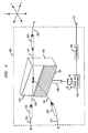
- FIGS. 3 and 4 illustrate two embodiments of the hitless wavelength-tunable optical filter incorporated within a WDM add/drop device.
- FIG. 3 is a diagram of the add/drop device 300 in which the filter type used is a multi-layer tunable dielectric filter and the filter is positioned using well-known lateral slide tuning of a wedge filter to select a particular wavelength channel for add/drop.
- FIG. 4 is a diagram of the add/drop device 400 in which the filter type used is a Fabry-Perot interference filter and the filter is positioned using well-known rotational tuning to select a particular wavelength channel for add/drop.
- the pass band selected for transmission through the filter region 110 of the device is determined by the angle of incidence of the incident composite optical signal beam 130, thus a rotational tuning scheme is used.
- filter means and types may also be utilized and still embody the principles of the present invention, including, but not limited to, and tunable Mach-Zehnder interferometers, to name a few.
- tuning means could also be utilized and still embody the principles of the present invention, including, but not limited to, piezoelectric actuation tuning, manual tuning, synchro/servo tuning, mechanical ratchet tuning, to name a few.
- an optical beam collimator 350 is coupled to an optical fiber 355 as a means for providing the incident composite optical signal beam 130 to be imparted upon the hitless wavelength-tunable optical filter 100.
- An optical beam collimator 360 is coupled to an optical fiber 365 for providing the transmitted wavelength channel optical signal beam 140 for adding/dropping through the hitless wavelength-tunable optical filter 100.
- An optical beam collimator 370 is coupled to an optical fiber 375 for providing the reflected composite optical signal beam 150 from the hitless wavelength-tunable optical filter 100.
- a positioning coupler 330 is utilized to couple the hitless wavelength-tunable optical filter 100 to a filter positioner.
- an XZ positioner 325 is used, since positioning with only two degrees of freedom is required.
- Device positioning along the x -axis changes the point of incidence at which the optical signal beams strike the surface of the filter region 110 and therefore the wavelength channel which is transmitted through the device is changed.
- Device positioning along the z -axis changes the point of incidence of the optical signal beam from between the filter region 110 and the broadband reflective region 120, and therefore determines whether the filter is active and passing a wavelength channel, or the broadband reflective region is active and reflecting the entire incident composite optical signal beam.
- a controller 320 adapted to receive controller input signals 310 containing instructions as to the wavelength channel to be added or dropped.
- the controller 320 accepts the controller input signals 320 and responds by generating position signals coupled to the positioner, and which provide the positioner with the positioning information needed to add or drop the wavelength channel desired.
- relative repositioning between the hitless wavelength-tunable optical filter and the optical signal beams from a set of collimators is produced using a positionable filter and a fixed set of collimators.
- relative repositioning between the hitless wavelength-tunable optical filter and the optical signal beams from a set of collimators may be realized (i) utilizing a fixed filter and a positionable set of collimators, or (ii) utilizing both a positionable filter and a positionable set of collimators, and still embody the principles of the present invention.
- controller may be provided through the use of dedicated hardware as well as hardware capable of executing software in association with appropriate software.
- the functions may be provided by a single dedicated processor, by a single shared processor, or by a plurality of individual processors, some of which may be shared.
- explicit use of the term "controller” should not be construed to refer exclusively to hardware capable of executing software, and may implicitly include, without limitation, digital signal processor (DSP) hardware, read-only memory (ROM) for storing software, random access memory (RAM), and non-volatile storage.
- DSP digital signal processor
- ROM read-only memory
- RAM random access memory
- non-volatile storage Other hardware, conventional and/or custom, may also be included.
Landscapes
- Physics & Mathematics (AREA)
- General Physics & Mathematics (AREA)
- Optics & Photonics (AREA)
- Spectroscopy & Molecular Physics (AREA)
- Optical Communication System (AREA)
- Mechanical Light Control Or Optical Switches (AREA)
- Optical Head (AREA)
- Optical Filters (AREA)
Abstract
Description
Claims (10)
- An optical add/drop device comprising a hitless wavelength-tunable optical filter.
- A wavelength-tunable add/drop device comprising:a first region operable to add or drop a optical wavelength channel selected from a plurality of optical wavelength channels; anda second region, adjacent to said first region, said second region operable as a broadband optical reflector.
- The add/drop device of claim 2 wherein said second region includes a metallic coating to function as said broadband optical reflector.
- The add/drop device of claim 2 wherein said second region is comprised of at least one reflective dielectric layer.
- The add/drop device of claim 2 wherein said first region is comprised of a tunable optical filter.
- A method for the tuning of a wavelength-tunable optical filter from a first wavelength channel to a second wavelength channel, the method comprising the steps of:repositioning an optical signal beam along a first wavelength channel track on said wavelength-tunable optical filter to a region of broadband reflectance;repositioning said optical signal beam within said region of broadband reflectance to a position associated with said second wavelength channel; andrepositioning said optical signal beam from said region of broadband reflectance along a second wavelength channel track on said wavelength-tunable optical filter.
- A wavelength-tunable optical device comprising:a broadband reflective surface; anda wavelength-tunable optical filter adjacent to said broadband reflective surface.
- The device of claim 7 wherein said broadband reflective surface is a metallic coating.
- A method for the tuning of a wavelength-tunable optical filter from a first wavelength channel to a second wavelength channel, the method comprising:repositioning an optical signal beam from a position on said filter corresponding to said first wavelength channel, into a region of broadband reflectance; while maintaining an optical bandpass for a signal associated with said first wavelength channel until said optical signal beam is repositioned into said region of broadband reflectance;repositioning said optical signal beam to a position within said region of broadband reflectance so that when said optical signal beam is returned to said filter, an optical bandpass for a signal associated with said second wavelength channel is established; andrepositioning said optical signal beam from said region of broadband reflectance to a position on said filter corresponding to said second wavelength channel; while maintaining said optical bandpass for said signal associated with said second wavelength channel.
- A hitless wavelength-tunable optical add/drop device comprising:means for repositioning an optical signal beam from a position on a wavelength-tunable filter corresponding to a first wavelength channel, into a region of broadband reflectance; while maintaining a first optical bandpass for a signal associated with said first wavelength channel until said optical signal beam is repositioned into said region of broadband reflectance;means for repositioning said optical signal beam to a position within said region of broadband reflectance so that when said optical signal beam is returned to said wavelength-tunable filter, a second optical bandpass for a signal associated with a second wavelength channel is established; andmeans for repositioning said optical signal beam from said region of broadband reflectance to a position on said wavelength-tunable filter corresponding to said second wavelength channel; while maintaining said second optical bandpass for said signal associated with said second wavelength channel.
Applications Claiming Priority (2)
| Application Number | Priority Date | Filing Date | Title |
|---|---|---|---|
| US503515 | 2000-02-14 | ||
| US09/503,515 US6292299B1 (en) | 2000-02-14 | 2000-02-14 | Tunable optical add/drop device and method |
Publications (3)
| Publication Number | Publication Date |
|---|---|
| EP1130432A2 true EP1130432A2 (en) | 2001-09-05 |
| EP1130432A3 EP1130432A3 (en) | 2003-05-14 |
| EP1130432B1 EP1130432B1 (en) | 2004-08-25 |
Family
ID=24002409
Family Applications (1)
| Application Number | Title | Priority Date | Filing Date |
|---|---|---|---|
| EP00307369A Expired - Lifetime EP1130432B1 (en) | 2000-02-14 | 2000-08-29 | Hitless wavelength-tunable optical add/drop device |
Country Status (6)
| Country | Link |
|---|---|
| US (1) | US6292299B1 (en) |
| EP (1) | EP1130432B1 (en) |
| JP (1) | JP2001290089A (en) |
| AU (1) | AU1971301A (en) |
| CA (1) | CA2330729C (en) |
| DE (1) | DE60013241T2 (en) |
Cited By (9)
| Publication number | Priority date | Publication date | Assignee | Title |
|---|---|---|---|---|
| WO2003096583A1 (en) * | 2002-05-08 | 2003-11-20 | Lambda Crossing Ltd. | Method and device for tunable frequency selective filtering of optical signals |
| GB2389917A (en) * | 2002-06-05 | 2003-12-24 | Raytheon Co | Selectable filter module for optical fibre transmission system |
| JP3530840B2 (en) | 2001-10-10 | 2004-05-24 | サンテック株式会社 | Variable wavelength splitter, variable wavelength multiplexer, and wavelength routing device |
| WO2011085144A1 (en) * | 2010-01-08 | 2011-07-14 | Semrock, Inc. | Tunable thin-film filter |
| US8508849B2 (en) | 2006-05-12 | 2013-08-13 | Semrock, Inc. | Multiphoton fluorescence filters |
| US8879150B1 (en) | 2009-03-20 | 2014-11-04 | Semrock, Inc. | Optical thin-film polarizing bandpass filter |
| US8958156B1 (en) | 2007-05-30 | 2015-02-17 | Semrock, Inc. | Interference filter for non-zero angle of incidence spectroscopy |
| US9304237B1 (en) | 2012-12-10 | 2016-04-05 | Semrock, Inc. | Tunable band-pass filter |
| US9354370B1 (en) | 2007-09-25 | 2016-05-31 | Semrock, Inc. | Optical thin-film notch filter with very wide pass band regions |
Families Citing this family (17)
| Publication number | Priority date | Publication date | Assignee | Title |
|---|---|---|---|---|
| US6587608B2 (en) | 2000-11-14 | 2003-07-01 | Chameleon Optics, Inc. | Reconfigurable, all optical add/drop nodes using non-interrupting switching apparatus and methods |
| US6542659B2 (en) * | 2000-12-01 | 2003-04-01 | Axsun Technologies, Inc. | Optical spectrum analyzer with beam switch array |
| US6829067B2 (en) * | 2000-12-04 | 2004-12-07 | California Institute Of Technology | Method and apparatus for implementing a multi-channel tunable filter |
| US7062174B2 (en) * | 2001-01-22 | 2006-06-13 | Essex Corporation | Wavelength division multiplexing add-drop multiplexer using an optical tapped delay line |
| WO2002058285A2 (en) * | 2001-01-22 | 2002-07-25 | Essex Corporation | Optical cdma communications system using otdl device |
| JP2002277757A (en) * | 2001-03-16 | 2002-09-25 | Ando Electric Co Ltd | Tunable filter |
| US6781757B2 (en) | 2001-04-20 | 2004-08-24 | Micron Optics, Inc. | Polarization insensitive tunable optical filters |
| US6791736B2 (en) | 2001-06-19 | 2004-09-14 | Teralum Llc | Optical device for dispersion compensation |
| US7509048B2 (en) * | 2001-07-20 | 2009-03-24 | Essex Corporation | Method and apparatus for optical signal processing using an optical tapped delay line |
| US20030156780A1 (en) * | 2001-10-24 | 2003-08-21 | Lambda Crossing, Ltd. | Tunable filter |
| US7035484B2 (en) * | 2002-04-12 | 2006-04-25 | Xtellus, Inc. | Tunable optical filter |
| US7062122B2 (en) * | 2002-11-05 | 2006-06-13 | Jds Uniphase Corporation | Tunable optical add/drop device |
| JP2005140831A (en) * | 2003-11-04 | 2005-06-02 | Fujitsu Ltd | Wavelength characteristic variable filter |
| US7454143B1 (en) * | 2003-12-15 | 2008-11-18 | Avanex Corporation | Reconfigurable thin film based DWDM devices for reconfigurable add-drop optical systems |
| US7248758B2 (en) * | 2005-06-08 | 2007-07-24 | Verizon Business Global Llc | Hitless tunable filter |
| US7576860B2 (en) * | 2007-05-11 | 2009-08-18 | Hewlett-Packard Development Company, L.P. | Light filter having a wedge-shaped profile |
| CN115061241B (en) * | 2022-08-04 | 2022-11-18 | 上海羲禾科技有限公司 | Wavelength division multiplexer |
Family Cites Families (12)
| Publication number | Priority date | Publication date | Assignee | Title |
|---|---|---|---|---|
| JPS6186715A (en) * | 1984-10-04 | 1986-05-02 | Matsushita Electric Ind Co Ltd | Optical demultiplexer/multiplexer |
| US5872655A (en) | 1991-07-10 | 1999-02-16 | Optical Coating Laboratory, Inc. | Monolithic linear variable filter and method of manufacture |
| JPH06281813A (en) | 1993-01-29 | 1994-10-07 | Nec Corp | Transmission wavelength variable device |
| US5481402A (en) * | 1994-02-22 | 1996-01-02 | Jds Fitel Inc. | Tunable optical filter |
| US5812291A (en) * | 1995-03-22 | 1998-09-22 | Cselt Centro Studi E Laboratori Telecomunicazioni S.P.A. | Optical add-drop multiplexer for optical communication networks |
| US5781341A (en) | 1995-06-30 | 1998-07-14 | Dicon Fiberoptics, Inc. | Motorized tunable filter and motorized variable attenuator |
| JP3754728B2 (en) * | 1995-08-08 | 2006-03-15 | 富士通株式会社 | Optical device |
| JP3540062B2 (en) * | 1995-08-28 | 2004-07-07 | 富士通株式会社 | Tunable filter module |
| JP2768320B2 (en) | 1995-09-04 | 1998-06-25 | 日本電気株式会社 | Tunable optical filter |
| KR100219633B1 (en) * | 1997-02-22 | 1999-09-01 | 윤종용 | Tuning filter unit for optical communication |
| US5892612A (en) | 1997-08-07 | 1999-04-06 | Cambridge Research & Instrumentation Inc. | Tunable optical filter with white state |
| US6545739B1 (en) * | 1997-09-19 | 2003-04-08 | Nippon Telegraph And Telephone Corporation | Tunable wavelength filter using nano-sized droplets of liquid crystal dispersed in a polymer |
-
2000
- 2000-02-14 US US09/503,515 patent/US6292299B1/en not_active Expired - Lifetime
- 2000-08-29 DE DE60013241T patent/DE60013241T2/en not_active Expired - Lifetime
- 2000-08-29 EP EP00307369A patent/EP1130432B1/en not_active Expired - Lifetime
-
2001
- 2001-01-10 CA CA002330729A patent/CA2330729C/en not_active Expired - Fee Related
- 2001-02-12 AU AU19713/01A patent/AU1971301A/en not_active Abandoned
- 2001-02-14 JP JP2001036355A patent/JP2001290089A/en active Pending
Cited By (12)
| Publication number | Priority date | Publication date | Assignee | Title |
|---|---|---|---|---|
| JP3530840B2 (en) | 2001-10-10 | 2004-05-24 | サンテック株式会社 | Variable wavelength splitter, variable wavelength multiplexer, and wavelength routing device |
| WO2003096583A1 (en) * | 2002-05-08 | 2003-11-20 | Lambda Crossing Ltd. | Method and device for tunable frequency selective filtering of optical signals |
| US6671437B2 (en) | 2002-05-08 | 2003-12-30 | Lambda Crossing Ltd. | Method and device for tunable frequency selective filtering of optical signals |
| GB2389917A (en) * | 2002-06-05 | 2003-12-24 | Raytheon Co | Selectable filter module for optical fibre transmission system |
| US8508849B2 (en) | 2006-05-12 | 2013-08-13 | Semrock, Inc. | Multiphoton fluorescence filters |
| US8958156B1 (en) | 2007-05-30 | 2015-02-17 | Semrock, Inc. | Interference filter for non-zero angle of incidence spectroscopy |
| US9857511B2 (en) | 2007-05-30 | 2018-01-02 | Semrock, Inc. | Interference filter for non-zero angle of incidence spectroscopy |
| US9354370B1 (en) | 2007-09-25 | 2016-05-31 | Semrock, Inc. | Optical thin-film notch filter with very wide pass band regions |
| US8879150B1 (en) | 2009-03-20 | 2014-11-04 | Semrock, Inc. | Optical thin-film polarizing bandpass filter |
| WO2011085144A1 (en) * | 2010-01-08 | 2011-07-14 | Semrock, Inc. | Tunable thin-film filter |
| US8441710B2 (en) | 2010-01-08 | 2013-05-14 | Semrock, Inc. | Tunable thin-film filter |
| US9304237B1 (en) | 2012-12-10 | 2016-04-05 | Semrock, Inc. | Tunable band-pass filter |
Also Published As
| Publication number | Publication date |
|---|---|
| EP1130432A3 (en) | 2003-05-14 |
| AU1971301A (en) | 2001-08-16 |
| JP2001290089A (en) | 2001-10-19 |
| US6292299B1 (en) | 2001-09-18 |
| DE60013241T2 (en) | 2005-09-15 |
| CA2330729A1 (en) | 2001-08-14 |
| DE60013241D1 (en) | 2004-09-30 |
| EP1130432B1 (en) | 2004-08-25 |
| CA2330729C (en) | 2003-03-25 |
Similar Documents
| Publication | Publication Date | Title |
|---|---|---|
| EP1130432B1 (en) | Hitless wavelength-tunable optical add/drop device | |
| US5737104A (en) | Wavelength division multiplexer and demultiplexer | |
| US6320996B1 (en) | Wavelength selective optical switch | |
| US7352927B2 (en) | Optical add-drop multiplexer architecture with reduced effect of mirror edge diffraction | |
| EP0897547B1 (en) | Optical apparatus which uses a virtually imaged phased array to produce chromatic dispersion | |
| CA2029171C (en) | Multiport optical devices | |
| US5781341A (en) | Motorized tunable filter and motorized variable attenuator | |
| US6292298B1 (en) | Method and apparatus for realizing an optical multiplexer/demultiplexer | |
| US7346234B2 (en) | Reduction of MEMS mirror edge diffraction in a wavelength selective switch using servo-based multi-axes rotation | |
| US5905827A (en) | Optical multiplexer/demultiplexer and wavelength division multiplexing module | |
| US6829067B2 (en) | Method and apparatus for implementing a multi-channel tunable filter | |
| US6956700B1 (en) | Wavelength dispersion compensating apparatus | |
| US7262904B1 (en) | Tunable optical add/drop device | |
| JPH11223745A (en) | Apparatus with virtual image phase array (VIPA) in combination with a wavelength demultiplexer for demultiplexing wavelength multiplexed (WDM) light | |
| US20130258470A1 (en) | Reduction of polarization-dependent loss in double-pass grating configurations | |
| US20040130764A1 (en) | Angle tunable thin film interference optical filter for wavelength multiplexing | |
| US20050031256A1 (en) | Temperature compensation method of an optical wdm component and temperature-compensated optical wdm component | |
| WO2021051960A1 (en) | Spectral processing apparatus and reconfigurable optical add-drop multiplexer | |
| US20040101307A1 (en) | Optical device, terminal apparatus, and system for wavelength division multiplexing | |
| JPH10300915A (en) | Bandpass filter device | |
| US6741393B1 (en) | Optical system with optical frequency discriminator | |
| US7062122B2 (en) | Tunable optical add/drop device | |
| KR100351562B1 (en) | Demultiplexer | |
| JP3489072B2 (en) | Wavelength multiplexing / demultiplexing circuit | |
| JP7809389B2 (en) | Tunable wavelength filter |
Legal Events
| Date | Code | Title | Description |
|---|---|---|---|
| PUAI | Public reference made under article 153(3) epc to a published international application that has entered the european phase |
Free format text: ORIGINAL CODE: 0009012 |
|
| 17P | Request for examination filed |
Effective date: 20000907 |
|
| AK | Designated contracting states |
Kind code of ref document: A2 Designated state(s): AT BE CH CY DE DK ES FI FR GB GR IE IT LI LU MC NL PT SE |
|
| AX | Request for extension of the european patent |
Free format text: AL;LT;LV;MK;RO;SI |
|
| PUAL | Search report despatched |
Free format text: ORIGINAL CODE: 0009013 |
|
| AK | Designated contracting states |
Designated state(s): AT BE CH CY DE DK ES FI FR GB GR IE IT LI LU MC NL PT SE |
|
| AX | Request for extension of the european patent |
Extension state: AL LT LV MK RO SI |
|
| 17Q | First examination report despatched |
Effective date: 20030722 |
|
| AKX | Designation fees paid |
Designated state(s): DE FR GB IE IT |
|
| GRAP | Despatch of communication of intention to grant a patent |
Free format text: ORIGINAL CODE: EPIDOSNIGR1 |
|
| RTI1 | Title (correction) |
Free format text: HITLESS WAVELENGTH-TUNABLE OPTICAL ADD/DROP DEVICE |
|
| RTI1 | Title (correction) |
Free format text: HITLESS WAVELENGTH-TUNABLE OPTICAL ADD/DROP DEVICE |
|
| GRAS | Grant fee paid |
Free format text: ORIGINAL CODE: EPIDOSNIGR3 |
|
| GRAA | (expected) grant |
Free format text: ORIGINAL CODE: 0009210 |
|
| AK | Designated contracting states |
Kind code of ref document: B1 Designated state(s): DE FR GB IE IT |
|
| REG | Reference to a national code |
Ref country code: GB Ref legal event code: FG4D |
|
| REG | Reference to a national code |
Ref country code: IE Ref legal event code: FG4D |
|
| REF | Corresponds to: |
Ref document number: 60013241 Country of ref document: DE Date of ref document: 20040930 Kind code of ref document: P |
|
| ET | Fr: translation filed | ||
| PLBE | No opposition filed within time limit |
Free format text: ORIGINAL CODE: 0009261 |
|
| STAA | Information on the status of an ep patent application or granted ep patent |
Free format text: STATUS: NO OPPOSITION FILED WITHIN TIME LIMIT |
|
| 26N | No opposition filed |
Effective date: 20050526 |
|
| REG | Reference to a national code |
Ref country code: GB Ref legal event code: 732E Free format text: REGISTERED BETWEEN 20131121 AND 20131127 |
|
| REG | Reference to a national code |
Ref country code: FR Ref legal event code: CD Owner name: ALCATEL-LUCENT USA INC. Effective date: 20131122 |
|
| REG | Reference to a national code |
Ref country code: FR Ref legal event code: GC Effective date: 20140410 |
|
| REG | Reference to a national code |
Ref country code: FR Ref legal event code: RG Effective date: 20141015 |
|
| REG | Reference to a national code |
Ref country code: FR Ref legal event code: PLFP Year of fee payment: 16 |
|
| PGFP | Annual fee paid to national office [announced via postgrant information from national office to epo] |
Ref country code: IE Payment date: 20150820 Year of fee payment: 16 |
|
| REG | Reference to a national code |
Ref country code: FR Ref legal event code: PLFP Year of fee payment: 17 |
|
| REG | Reference to a national code |
Ref country code: IE Ref legal event code: MM4A |
|
| PG25 | Lapsed in a contracting state [announced via postgrant information from national office to epo] |
Ref country code: IE Free format text: LAPSE BECAUSE OF NON-PAYMENT OF DUE FEES Effective date: 20160829 |
|
| REG | Reference to a national code |
Ref country code: FR Ref legal event code: PLFP Year of fee payment: 18 |
|
| REG | Reference to a national code |
Ref country code: FR Ref legal event code: PLFP Year of fee payment: 19 |
|
| PGFP | Annual fee paid to national office [announced via postgrant information from national office to epo] |
Ref country code: IT Payment date: 20180830 Year of fee payment: 19 Ref country code: FR Payment date: 20180827 Year of fee payment: 19 Ref country code: DE Payment date: 20180823 Year of fee payment: 19 |
|
| PGFP | Annual fee paid to national office [announced via postgrant information from national office to epo] |
Ref country code: GB Payment date: 20180822 Year of fee payment: 19 |
|
| REG | Reference to a national code |
Ref country code: DE Ref legal event code: R119 Ref document number: 60013241 Country of ref document: DE |
|
| GBPC | Gb: european patent ceased through non-payment of renewal fee |
Effective date: 20190829 |
|
| PG25 | Lapsed in a contracting state [announced via postgrant information from national office to epo] |
Ref country code: DE Free format text: LAPSE BECAUSE OF NON-PAYMENT OF DUE FEES Effective date: 20200303 Ref country code: FR Free format text: LAPSE BECAUSE OF NON-PAYMENT OF DUE FEES Effective date: 20190831 |
|
| PG25 | Lapsed in a contracting state [announced via postgrant information from national office to epo] |
Ref country code: IT Free format text: LAPSE BECAUSE OF NON-PAYMENT OF DUE FEES Effective date: 20190829 Ref country code: GB Free format text: LAPSE BECAUSE OF NON-PAYMENT OF DUE FEES Effective date: 20190829 |