EP1130380A2 - Method of measuring reflection off multilayer dielectric coating - Google Patents
Method of measuring reflection off multilayer dielectric coating Download PDFInfo
- Publication number
- EP1130380A2 EP1130380A2 EP01102124A EP01102124A EP1130380A2 EP 1130380 A2 EP1130380 A2 EP 1130380A2 EP 01102124 A EP01102124 A EP 01102124A EP 01102124 A EP01102124 A EP 01102124A EP 1130380 A2 EP1130380 A2 EP 1130380A2
- Authority
- EP
- European Patent Office
- Prior art keywords
- energy
- dielectric materials
- set forth
- angle
- polarized
- Prior art date
- Legal status (The legal status is an assumption and is not a legal conclusion. Google has not performed a legal analysis and makes no representation as to the accuracy of the status listed.)
- Withdrawn
Links
- 238000000034 method Methods 0.000 title claims abstract description 23
- 238000000576 coating method Methods 0.000 title description 10
- 239000011248 coating agent Substances 0.000 title description 4
- 239000003989 dielectric material Substances 0.000 claims abstract description 25
- 230000000295 complement effect Effects 0.000 claims abstract description 8
- 238000001914 filtration Methods 0.000 claims 1
- 238000001228 spectrum Methods 0.000 claims 1
- 238000010521 absorption reaction Methods 0.000 abstract description 17
- 230000010287 polarization Effects 0.000 description 4
- 238000002310 reflectometry Methods 0.000 description 3
- 238000010586 diagram Methods 0.000 description 2
- 238000005259 measurement Methods 0.000 description 2
- 238000012986 modification Methods 0.000 description 2
- 230000004048 modification Effects 0.000 description 2
- 230000003287 optical effect Effects 0.000 description 2
- 230000002411 adverse Effects 0.000 description 1
- 238000009529 body temperature measurement Methods 0.000 description 1
- 238000009792 diffusion process Methods 0.000 description 1
- 230000028161 membrane depolarization Effects 0.000 description 1
Images


Classifications
-
- G—PHYSICS
- G01—MEASURING; TESTING
- G01N—INVESTIGATING OR ANALYSING MATERIALS BY DETERMINING THEIR CHEMICAL OR PHYSICAL PROPERTIES
- G01N21/00—Investigating or analysing materials by the use of optical means, i.e. using sub-millimetre waves, infrared, visible or ultraviolet light
- G01N21/17—Systems in which incident light is modified in accordance with the properties of the material investigated
- G01N21/21—Polarisation-affecting properties
Definitions
- the present invention relates to a method of measuring reflected and absorbed energy, and more particularly to a method of measuring reflected and absorbed energy off an optic covered with multilayers of dielectric material.
- High energy lasers employ mirrors and lenses to form and direct the high energy laser beam.
- the amount of energy contained in the high energy impulse is so great that it would destroy the optical quality of the lens and potentially cause . catastrophic failure. Consequently, the lenses are coated with multiple layers of alternating dielectric materials to reflect the beam and prevent it from being absorbed by, and hence thermally distorting and destroying, the lenses.
- 32 paired-layers of dielectric material are used to coat the lens.
- High energy laser are particularly sensitive to adverse impact of absorbed energy since the high power levels results in coating with low absorption levels.
- laser absorption calorimetery In order to measure the reflectivity and absorption characteristics of a lens covered with multilayer dielectric materials laser absorption calorimetery has been used since the mid 1980s.
- This method comprises a high energy laser that generates light in the infrared and direct it towards an optic coated with multiple layers of alternating dielectric materials that is to be tested for its reflectivity.
- the optic is instrumented with temperature measurement devices to measure the amount of energy absorbed by the optic.
- Another device measures the amount of energy of the incident laser beam. By dividing the amount of energy absorbed by the optic with the amount of energy incident on the optic, the absorption of optic can be measured.
- the equipment necessary to support the above test are complex and expensive. Since the absorption of the multilayered dielectric coated optic is very low, the energy of the incident laser must be very high to register a measurable temperature increase on the test optic. High power laser are expensive to maintain and operate. Also, for larger optic with their higher thermal mass, the amount of incident energy to necessary to register a temperature increase increases.
- the preceding and other shortcomings of the prior art are addressed and overcome by the present invention which provides generally a method of measuring the reflection off a lens covered with multiple layers of dielectric materials.
- the method comprises directing a beam of polarized light against the dielectric materials, polarizing the diffused beam of reflected light, and measuring the energy in the polarized diffused beam of reflected light.
- the energy is representative of the reflective properties of the multilayers of dielectric materials.
- the diffused beam is polarized at an angle that is complementary to the angle of the linearly polarized light that is directed against the dielectric materials. The complementary angle serves to minimize the amount of energy in, and null the diffused beam of reflected light.
- FIG. 1 is a schematic diagram of the method for measuring the reflection off a lens covered with multilayers of dielectric materials in accordance with the present invention.
- FIG. 2 is a graph of the distribution of energy at various polarization states in degrees.
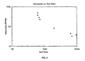
- FIG. 3 is a graph of null ratio versus energy absorption for several multilayer dielectric coatings.
- the present invention provides a method for measuring the reflection off a lens coated with multilayers of dielectric materials, generally designated by the numeral 10.
- the method 10 employs means for generating an optical signal 14.
- the means 14 is preferably a Nernst glower that generates light energy in the infrared.
- a polarizer 16 serves to linearly polarize the generated light shown by the arrow 17.
- the polarizer is preferably set to polarize the light at an angle of 125°, although any angle could be used.
- the polarized light is reflected off an optic 18.
- the optic 18 comprises a lens shown schematically by the numeral 20 coated, or covered, with an even number of dielectric layers 22 and 24 of alternating paired layers of dielectric materials that are substantially ⁇ /2 in thickness.
- a typical dielectric stack will have reflectance in excess of 99.95% of incident energy. Thus, they protect the optic 18 from absorbing the light energy, which in the case of a high energy laser would thermally distort and eventually destroy the lens.
- the optic 18 is planar and has a diameter of 2.0 inches, although it can be conical with a diameter of 20 inches, or have a contoured geometry.
- a graph illustrates the distribution of energy at various angles of polarization.
- graph 30 shows the polarization state of reflected light from an ideal reflector where each of the paired dielectric layers is ⁇ /2. It should be recognized that the reflected light peaks at 125° with a waveform that generally resembles an impulse, much of the energy being within ⁇ 5° of the central 125° polarization angle. This represents a multilayer dielectric with very low absorption (VLA).
- VLA very low absorption
- the graph 32 which represents the distribution of energy off the actual paired dielectric layers 22 and 24 which approximate, but are not exactly equal to, ⁇ /2 in thickness. As shown, the distribution is diffused having a normalized amplitude of about 45% of the incident energy. In this case the distribution extends over ⁇ 35% of the central 125°. Again, the greater the shift, the greater the diffusion and the less reflective the multilayer dielectric.
- the reflected light passes through a polarizer 40.
- the polarizer 40 is rotated to, and set at an angle that is complementary (approximately ⁇ 90°) to the angle of the polarizer 16. In the preferred embodiment it is set to an angle of either 35° or 215°.
- This complementary relationship acts effectively causing the polarizer 40 to function as a band pass filter and serves to null the reflected light and minimize the total light energy detected by a detector 42.
- the detector 42 is preferably a sensitive IR detector. In the case of the ideal dielectric reflector shown in graph 30 a perfect null would be created and no energy would be detected by the detector 42.
- the diffused energy is widespread so significant portions of it extend beyond the band pass limits of the polarizer 40. Hence, this energy is detected by the detector 42.
- the amount of energy detected represents the depolarization due to the multilayer dielectric structure's non-ideal reflection of the incident energy. Accordingly, when large amounts of energy are detected, much of the incident energy is absorbed by the lens 20.
- Such a dielectric configuration should not be used as a coating for high energy lasers. It should be noted that the reflectance and absorption of low absorbing filters is a function of the null ratio and that the measurement of the null ratio provides a measurement of the absorption of the film.
- a graph is shown of null ratio versus energy absorption for eight dielectric coatings.
- the abscissa null ratios (NR) varies logarithmically between 100 and 10,000.
- the NR is equal to the light energy transmitted divided by the detected energy when the polarizer 40 is in the null position.
- the absorption of the coatings is shown as the ordinate and it varies logarithmically between 0 and 500 parts per million.
- an absorption requirement is selected. Hence, for a requirement that the absorption be less than 200 parts per million, the coatings shown to the left of a vertical line passing through an absorption equal to 200 meet the requirement.
- the coatings to the right of the line are too absorptive and should not be used, as they would not protect the underlying lens. Coatings could be added to the chart as additional tests are made.
- a rotating filter wheel 44 with a carousel of filters can be utilized to distribute the nulled, polarized light into wavelength components.
- a computer 46 or data processor serves to store the data collected by the detector 42 and also the absorption data shown in FIG. 3.
- the computer can be programmed to compare the detected energy to the absorption requirements and read or display the results on a display 50.
Landscapes
- Physics & Mathematics (AREA)
- Health & Medical Sciences (AREA)
- Life Sciences & Earth Sciences (AREA)
- Chemical & Material Sciences (AREA)
- Analytical Chemistry (AREA)
- Biochemistry (AREA)
- General Health & Medical Sciences (AREA)
- General Physics & Mathematics (AREA)
- Immunology (AREA)
- Pathology (AREA)
- Investigating Or Analysing Materials By Optical Means (AREA)
- Testing Of Optical Devices Or Fibers (AREA)
Abstract
Description
Claims (11)
- A method of measuring the reflection off a lens covered with multilayers of dielectric materials comprising:directing a beam of polarized light against the dielectric materials; polarizing the diffused beam of reflected light; andmeasuring the energy in the polarized diffused beam of reflected light, said energy being representative of the reflective properties of the multilayers of dielectric materials.
- The method as set forth in claim 1 wherein the step of polarizing comprises polarizing the diffused beam at an angle that is complementary to the angle of the polarized light that is directed against the dielectric materials.
- The method as set forth in claim 2 wherein said polarized light is linearly polarized.
- The method as set forth in claim 1 wherein said light directed against the dielectric materials is polarized at a first angle, and said diffused beam of reflected light is polarized at a second angle that is complementary to said first angle.
- The method as set forth in claim 4 wherein said second angle serves to minimize the amount of energy in the diffused beam.
- The method as set forth in claim 4 wherein said second angle serves to null the diffused beam of reflected light.
- The method as set forth in claim 4 and further comprising filtering the diffused beam of reflected light to provide a distribution of energy over a spectrum of wavelengths.
- The method as set forth in claim 4 including comparing the measured energy against a data base having reflective properties of other multilayers of dielectric materials, and determining whether the measured reflection is satisfactory.
- The method as set forth in claim 8 and further displaying the measured energy.
- The method as set forth in claim 8 and further comprising storing the data base in a data processor.
- The method as set forth in claim 1 wherein the paired multilayer dielectric materials have a thickness approximating λ/2 of the polarized light.
Applications Claiming Priority (2)
| Application Number | Priority Date | Filing Date | Title |
|---|---|---|---|
| US51020200A | 2000-02-22 | 2000-02-22 | |
| US510202 | 2000-02-22 |
Publications (2)
| Publication Number | Publication Date |
|---|---|
| EP1130380A2 true EP1130380A2 (en) | 2001-09-05 |
| EP1130380A3 EP1130380A3 (en) | 2002-01-02 |
Family
ID=24029768
Family Applications (1)
| Application Number | Title | Priority Date | Filing Date |
|---|---|---|---|
| EP01102124A Withdrawn EP1130380A3 (en) | 2000-02-22 | 2001-01-31 | Method of measuring reflection off multilayer dielectric coating |
Country Status (2)
| Country | Link |
|---|---|
| EP (1) | EP1130380A3 (en) |
| JP (1) | JP2001264211A (en) |
Family Cites Families (2)
| Publication number | Priority date | Publication date | Assignee | Title |
|---|---|---|---|---|
| JPH0627706B2 (en) * | 1985-04-25 | 1994-04-13 | オリンパス光学工業株式会社 | Reflectance measuring device |
| JPH05172748A (en) * | 1991-12-25 | 1993-07-09 | Maki Seisakusho:Kk | Reflection spectroscopy measuring method and apparatus |
-
2001
- 2001-01-31 EP EP01102124A patent/EP1130380A3/en not_active Withdrawn
- 2001-02-16 JP JP2001039948A patent/JP2001264211A/en active Pending
Also Published As
| Publication number | Publication date |
|---|---|
| JP2001264211A (en) | 2001-09-26 |
| EP1130380A3 (en) | 2002-01-02 |
Similar Documents
| Publication | Publication Date | Title |
|---|---|---|
| US6411385B2 (en) | Thin film optical measurement system and method with calibrating ellipsometer | |
| US6515744B2 (en) | Small spot ellipsometer | |
| US5946098A (en) | Optical elements for use in spectroscopic ellipsometer and polarimeter systems | |
| US6118537A (en) | Multiple tipped berek plate optical retarder elements for use in spectroscopic ellipsometer and polarimeter systems | |
| US6100981A (en) | Dual horizontally oriented triangle shaped optical retarder element for use in spectroscopic ellipsometer and polarimeter systems | |
| US6141102A (en) | Single trianglular shaped optical retarder element for use in spectroscopic ellipsometer and polarimeter systems | |
| US6084674A (en) | Parallelogram shaped optical retarder element for use in spectroscopic ellipsometer and polarimeter systems | |
| EP0974042B1 (en) | Polarimeter and corresponding measuring method | |
| US20070263220A1 (en) | Optical Measurement System with Simultaneous Multiple Wavelengths, Multiple Angles of Incidence and Angles of Azimuth | |
| US4842404A (en) | Dual detector laser beam power monitor | |
| JP2005515465A (en) | Spectrometer with reduced polarization and multi-element depolarizer therefor | |
| US5381233A (en) | Polarized-light scatterometer for measuring the thickness of a film coated on the partial of a substrate | |
| US5966195A (en) | Method of determining cell thickness and twist angle parameters of liquid crystal cell | |
| US8309899B1 (en) | Systems for image acquisition | |
| Rochford et al. | Design and performance of a stable linear retarder | |
| Graebner | Measurement of thermal diffusivity by optical excitation and infrared detection of a transient thermal grating | |
| JPS62266439A (en) | Spectral temporary optical analyzer | |
| Angervaks et al. | A holographic prism based on photo-thermo-refractive glass: requirements and possibilities | |
| CN108225742A (en) | A kind of method and device for depolarizer performance detection | |
| CN208000191U (en) | A kind of depolarizer detection device | |
| Brandenberg | 10-THE REFLECTIVITY OF SOLIDS AT GRAZ-ING ANGLES | |
| JP2001264211A (en) | Method for measuring the loss of reflection from a lens coated with multiple layers of dielectric material | |
| Kimura et al. | Photoacoustic calorimetry system for glancing incidence mirror absorptance measurements | |
| JP3220252B2 (en) | EO probe | |
| ANGLES | 10-THE REFLECTIVITY OF SOLIDS AT GRAZ |
Legal Events
| Date | Code | Title | Description |
|---|---|---|---|
| PUAI | Public reference made under article 153(3) epc to a published international application that has entered the european phase |
Free format text: ORIGINAL CODE: 0009012 |
|
| AK | Designated contracting states |
Kind code of ref document: A2 Designated state(s): AT BE CH CY DE DK ES FI FR GB GR IE IT LI LU MC NL PT SE TR |
|
| AX | Request for extension of the european patent |
Free format text: AL;LT;LV;MK;RO;SI |
|
| PUAL | Search report despatched |
Free format text: ORIGINAL CODE: 0009013 |
|
| AK | Designated contracting states |
Kind code of ref document: A3 Designated state(s): AT BE CH CY DE DK ES FI FR GB GR IE IT LI LU MC NL PT SE TR |
|
| AX | Request for extension of the european patent |
Free format text: AL;LT;LV;MK;RO;SI |
|
| RIC1 | Information provided on ipc code assigned before grant |
Free format text: 7G 01N 21/21 A, 7G 01M 11/02 B |
|
| STAA | Information on the status of an ep patent application or granted ep patent |
Free format text: STATUS: THE APPLICATION HAS BEEN WITHDRAWN |
|
| 18W | Application withdrawn |
Withdrawal date: 20020506 |