EP1130362A2 - Magnetic encoder and method of manufacturing same - Google Patents
Magnetic encoder and method of manufacturing same Download PDFInfo
- Publication number
- EP1130362A2 EP1130362A2 EP01104162A EP01104162A EP1130362A2 EP 1130362 A2 EP1130362 A2 EP 1130362A2 EP 01104162 A EP01104162 A EP 01104162A EP 01104162 A EP01104162 A EP 01104162A EP 1130362 A2 EP1130362 A2 EP 1130362A2
- Authority
- EP
- European Patent Office
- Prior art keywords
- magnetic
- magnetization
- magnetic encoder
- encoder
- pole
- Prior art date
- Legal status (The legal status is an assumption and is not a legal conclusion. Google has not performed a legal analysis and makes no representation as to the accuracy of the status listed.)
- Granted
Links
Images


Classifications
-
- G—PHYSICS
- G01—MEASURING; TESTING
- G01P—MEASURING LINEAR OR ANGULAR SPEED, ACCELERATION, DECELERATION, OR SHOCK; INDICATING PRESENCE, ABSENCE, OR DIRECTION, OF MOVEMENT
- G01P3/00—Measuring linear or angular speed; Measuring differences of linear or angular speeds
- G01P3/42—Devices characterised by the use of electric or magnetic means
- G01P3/44—Devices characterised by the use of electric or magnetic means for measuring angular speed
- G01P3/443—Devices characterised by the use of electric or magnetic means for measuring angular speed mounted in bearings
-
- F—MECHANICAL ENGINEERING; LIGHTING; HEATING; WEAPONS; BLASTING
- F16—ENGINEERING ELEMENTS AND UNITS; GENERAL MEASURES FOR PRODUCING AND MAINTAINING EFFECTIVE FUNCTIONING OF MACHINES OR INSTALLATIONS; THERMAL INSULATION IN GENERAL
- F16C—SHAFTS; FLEXIBLE SHAFTS; ELEMENTS OR CRANKSHAFT MECHANISMS; ROTARY BODIES OTHER THAN GEARING ELEMENTS; BEARINGS
- F16C41/00—Other accessories, e.g. devices integrated in the bearing not relating to the bearing function as such
- F16C41/007—Encoders, e.g. parts with a plurality of alternating magnetic poles
-
- G—PHYSICS
- G01—MEASURING; TESTING
- G01P—MEASURING LINEAR OR ANGULAR SPEED, ACCELERATION, DECELERATION, OR SHOCK; INDICATING PRESENCE, ABSENCE, OR DIRECTION, OF MOVEMENT
- G01P3/00—Measuring linear or angular speed; Measuring differences of linear or angular speeds
- G01P3/42—Devices characterised by the use of electric or magnetic means
- G01P3/44—Devices characterised by the use of electric or magnetic means for measuring angular speed
- G01P3/48—Devices characterised by the use of electric or magnetic means for measuring angular speed by measuring frequency of generated current or voltage
- G01P3/481—Devices characterised by the use of electric or magnetic means for measuring angular speed by measuring frequency of generated current or voltage of pulse signals
- G01P3/487—Devices characterised by the use of electric or magnetic means for measuring angular speed by measuring frequency of generated current or voltage of pulse signals delivered by rotating magnets
-
- F—MECHANICAL ENGINEERING; LIGHTING; HEATING; WEAPONS; BLASTING
- F16—ENGINEERING ELEMENTS AND UNITS; GENERAL MEASURES FOR PRODUCING AND MAINTAINING EFFECTIVE FUNCTIONING OF MACHINES OR INSTALLATIONS; THERMAL INSULATION IN GENERAL
- F16C—SHAFTS; FLEXIBLE SHAFTS; ELEMENTS OR CRANKSHAFT MECHANISMS; ROTARY BODIES OTHER THAN GEARING ELEMENTS; BEARINGS
- F16C19/00—Bearings with rolling contact, for exclusively rotary movement
- F16C19/02—Bearings with rolling contact, for exclusively rotary movement with bearing balls essentially of the same size in one or more circular rows
- F16C19/14—Bearings with rolling contact, for exclusively rotary movement with bearing balls essentially of the same size in one or more circular rows for both radial and axial load
- F16C19/18—Bearings with rolling contact, for exclusively rotary movement with bearing balls essentially of the same size in one or more circular rows for both radial and axial load with two or more rows of balls
- F16C19/181—Bearings with rolling contact, for exclusively rotary movement with bearing balls essentially of the same size in one or more circular rows for both radial and axial load with two or more rows of balls with angular contact
- F16C19/183—Bearings with rolling contact, for exclusively rotary movement with bearing balls essentially of the same size in one or more circular rows for both radial and axial load with two or more rows of balls with angular contact with two rows at opposite angles
- F16C19/184—Bearings with rolling contact, for exclusively rotary movement with bearing balls essentially of the same size in one or more circular rows for both radial and axial load with two or more rows of balls with angular contact with two rows at opposite angles in O-arrangement
-
- F—MECHANICAL ENGINEERING; LIGHTING; HEATING; WEAPONS; BLASTING
- F16—ENGINEERING ELEMENTS AND UNITS; GENERAL MEASURES FOR PRODUCING AND MAINTAINING EFFECTIVE FUNCTIONING OF MACHINES OR INSTALLATIONS; THERMAL INSULATION IN GENERAL
- F16C—SHAFTS; FLEXIBLE SHAFTS; ELEMENTS OR CRANKSHAFT MECHANISMS; ROTARY BODIES OTHER THAN GEARING ELEMENTS; BEARINGS
- F16C2326/00—Articles relating to transporting
- F16C2326/01—Parts of vehicles in general
- F16C2326/02—Wheel hubs or castors
-
- H—ELECTRICITY
- H01—ELECTRIC ELEMENTS
- H01F—MAGNETS; INDUCTANCES; TRANSFORMERS; SELECTION OF MATERIALS FOR THEIR MAGNETIC PROPERTIES
- H01F13/00—Apparatus or processes for magnetising or demagnetising
- H01F13/003—Methods and devices for magnetising permanent magnets
-
- Y—GENERAL TAGGING OF NEW TECHNOLOGICAL DEVELOPMENTS; GENERAL TAGGING OF CROSS-SECTIONAL TECHNOLOGIES SPANNING OVER SEVERAL SECTIONS OF THE IPC; TECHNICAL SUBJECTS COVERED BY FORMER USPC CROSS-REFERENCE ART COLLECTIONS [XRACs] AND DIGESTS
- Y10—TECHNICAL SUBJECTS COVERED BY FORMER USPC
- Y10T—TECHNICAL SUBJECTS COVERED BY FORMER US CLASSIFICATION
- Y10T29/00—Metal working
- Y10T29/49—Method of mechanical manufacture
- Y10T29/49002—Electrical device making
- Y10T29/49004—Electrical device making including measuring or testing of device or component part
Definitions
- the present invention relates to a magnetic encoder applied to a bearing having a function of detecting a rotational frequency or the direction of rotation, a wheel bearing having the magnetic encoder and a method of manufacturing a magnetic encoder.
- a magnetic encoder for detecting a rotational frequency or the like has such a structure that a magnetic member is circumferentially formed on an annular member and multipolarly magnetized in the circumferential direction.
- the magnetic encoder is rotated with a rotator so that a magnetic sensor closely opposed to the magnetic member detects the rotation thereby detecting the rotational frequency.
- the magnetic member of such a magnetic encoder is magnetized by one-shot magnetization or index magnetization.
- Fig. 17 is a diagram for illustrating a method of performing one-shot magnetization on a magnetic member of a magnetic encoder.
- a magnetic encoder 103 consisting of a metal ring 102 forming an annular member and a magnetic member 101 provided on the outer peripheral surface of the metal ring 102 is prepared.
- a magnetization yoke 111 supporting a plurality of exciting coils 112 is so arranged that the exciting coils 112 are opposed to the surface of the magnetic member 101 of the magnetic encoder 103. In this state, a current is fed to the exciting coils 112 in a prescribed direction, thereby magnetizing the magnetic member 101 and multipolarly magnetized in the circumferential direction.
- Fig. 18 is a diagram for illustrating a method of performing index magnetization on a magnetic member of a magnetic encoder.
- a magnetic encoder 203 consisting of a metal ring 202 forming an annular member and a magnetic member 201 provided on the outer peripheral surface of the metal ring 202 is prepared.
- a pair of tooth profiles of a magnetization yoke 211 having an exciting coil 212 wound thereon are closely arranged on the outer peripheral surface of the magnetic encoder 203.
- a current is fed to the exciting coil 212 for generating a magnetic flux passing through the magnetization yoke 211 in a prescribed direction, and the magnetic flux passing through the clearance between the tooth profiles magnetizes the magnetic member 201 for obtaining a pair of N and S poles.
- a step of rotating the magnetic encoder 203 by a prescribed angle and magnetizing the same is repeated thereby multipolarly magnetizing the overall periphery of the magnetic member 201 in the circumferential direction.
- This method is hereinafter referred to as surface layer magnetization.
- the magnetization pitch is disadvantageously largely irregularized depending on the manufacturing accuracy for each magnetic pole or the way of winding the coil when the pitch is reduced to not more than a pole width of about 1.5 mm, although high magnetization strength is attained.
- the magnetization yoke 211 has a pair of tooth profiles and hence magnetization pitch accuracy is improved when attaining indexing accuracy of a spindle for rotating a workpiece. In this method, however, only the surface layer of the magnetic member 201 can be magnetized, disadvantageously leading to small magnetization strength.
- An object of the present invention is to provide a magnetic encoder having high magnetization strength similar to that in one-shot magnetization and a small magnetization pitch error similar to that in surface layer magnetization.
- Another object of the present invention is to provide a wheel bearing having a magnetic encoder having high magnetization strength and a small magnetization pitch error.
- a magnetic encoder comprises an annular member and a magnetic member circumferentially provided on the annular member and multipolarly magnetized in the circumferential direction, and is characterized in that a magnetization pitch error of the magnetic member is not more than 3 % and surface magnetization strength per unit magnetic pole is at least 30 mT/mm.
- surface magnetization strength per unit magnetic pole is a value obtained by dividing a maximum surface magnetization strength in one magnetic pole by the magnetic pole width.
- the magnetic encoder can detect a rotational frequency or the like with higher accuracy.
- the annular member preferably consists of a magnetic substance, and the magnetic member preferably consists of an elastomer mixed with magnetic powder.
- the annular member consists of a magnetic substance as described above, so that leakage of a magnetic flux can be suppressed in magnetization of the magnetic member and magnetization strength of the magnetic member is improved.
- a wheel bearing according to the present invention rotatably supporting a wheel has a rotating member provided with the aforementioned magnetic encoder, and is characterized in that the rotating member is so arranged that the magnetic encoder is closely opposed to a magnetic sensor for detecting the speed of rotation of the wheel.
- a wheel bearing provided with a magnetic encoder capable of rotating the speed of rotation of a wheel in high accuracy can be obtained.
- the aforementioned wheel bearing preferably has a fixed member rotatably supporting the rotating member, and the magnetic encoder preferably forms a sealing apparatus sealing an annular space between the rotating member and the fixed member.
- the magnetic encoder can also serve as the sealing apparatus, whereby increase of the number of components can be prevented.
- the sealing apparatus preferably has a sealing member mounted on the fixed member to be capable of coming into sliding contact with the annular member of the magnetic encoder.
- a method of manufacturing a magnetic encoder according to the present invention circumferentially providing a magnetic member on an annular member and magnetizing the magnetic member, arranges a magnetization yoke passing a magnetic flux for magnetizing the magnetic member to hold the magnetic member and the annular member so that the magnetic flux passes through and magnetizes the magnetic member in the portion held by the magnetization yoke for successively magnetizing the magnetic member along the circumferential direction thereby multipolarly magnetizing the magnetic member in the circumferential direction.
- the magnetization yoke thus holds the magnetic member and magnetizes the same so that the magnetic flux passes through the magnetic member, whereby magnetization strength can be increased similarly to that obtained by one-shot magnetization. Further, the magnetic member is magnetized every magnetic pole, whereby a magnetization pitch error can be reduced similarly to that obtained in surface layer magnetization so far as indexing accuracy of a spindle can be attained.
- the aforementioned method of manufacturing a magnetic encoder makes magnetization conditions variable in N pole magnetization and S pole magnetization of the peripheral surface of the magnetic member 1.
- N and S poles can be controlled to reach substantially identical magnetization strength by varying the magnetization conditions.
- the aforementioned method of manufacturing a magnetic encoder varies the value of a current fed to a coil wound on the magnetization yoke with the N pole magnetization and the S pole magnetization.
- the magnetization strength can be controlled with the value of the current.
- the aforementioned method of manufacturing a magnetic encoder varies the number of turns of a coil wound on the magnetization yoke with the N pole magnetization and the S pole magnetization.
- the magnetization strength can be controlled with the number of turns of the coil.
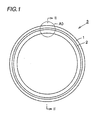
- a magnetic encoder 3 has a magnetic member 1 and a metal ring 2 forming an annular member.
- the magnetic member 1 has the so-called multipolarly magnetized structure in which N and S poles are alternately magnetized in the circumferential direction.
- This magnetic member 1 has a magnetization pitch error of not more than 3 % and surface magnetization strength of at least 30 mT/mm per unit magnetic pole.
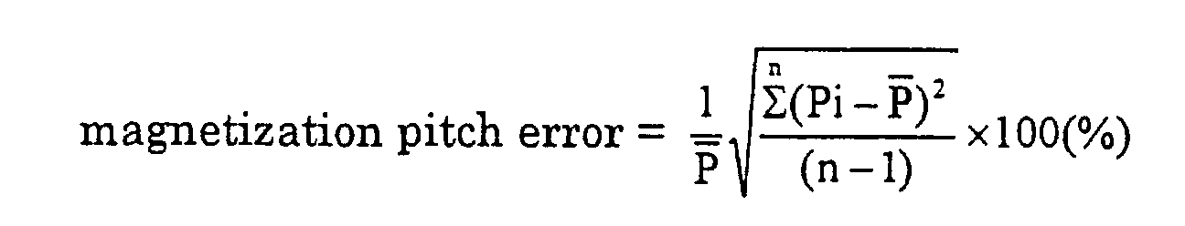
- the magnetization pitch error is obtained from magnetization strength distribution measured with a Hall sensor, for example.
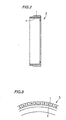
- a Hall sensor When measuring the magnetization strength of the magnetic member 1 shown in Fig. 1 with a Hall sensor, plus and minus rectangular digital signals are obtained with reference to a certain constant magnetization level as shown in Fig. 4B with respect to surface magnetization strength distribution having a waveform shown in Fig. 4A, for example.
- each pair of N and S poles are regarded as a single magnetic pole for obtaining the number n of magnetic poles, pitches P 1 , P 2 , ..., P n of the respective poles and an average magnetization pitch and calculating the magnetization pitch error on the basis of the above equation.
- the magnetization pitch error is zero.
- the magnetization strength is dispersed in practice as shown in Figs. 5A and 5B, and hence it follows that the magnetization pitches are dispersed to result in a magnetic pitch error.
- the surface magnetization strength on the surface (the outer peripheral surface) of the magnetic member 1 shown in Fig. 1 is magnetic flux density with a sensor air gap of substantially 0 mm. This surface magnetization strength is measured in a state approaching a gauss meter to the surface of the magnetic member 1, for example.
- the gauss meter employing a Hall device as a sensor obtains an analog electric signal proportionate to the magnetization strength, converts the output and displays the magnetization strength (magnetic flux density).
- surface magnetization strength per unit magnetic pole is a value obtained by dividing a maximum surface magnetization strength in one magnetic pole by the magnetic pole width.
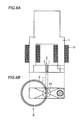
- a magnetization yoke 11 having exciting coils 12 wound thereon is fixed to hold the magnetic encoder 3 from the inner peripheral side and the outer peripheral side thereof, i.e., to hold both of the magnetic member 1 and the metal ring 2.
- the magnetic encoder 3 is mounted on a spindle (not shown) exhibiting small rotational run-out and having excellent indexing accuracy, and so set that outer diameter run-out of the magnetized surface is minimized.
- the magnetic encoder 3 is rotated at a speed of several 10 rpm in this state while a pulse-shaped current is fed to the exciting coils 12 in synchronization with angular displacement for magnetizing the magnetic encoder 3 at least once.
- the magnetic encoder 3 having the multipolarly magnetized magnetic member 1 can be manufactured.
- the magnetization pitch error is about ⁇ 0.1 %, i.e., not more than 3 %.
- Fig. 8 shows the relation between pole widths and the surface magnetization strength of the magnetic encoder 3 manufactured by the aforementioned method. It is understood from Fig. 8 that the surface magnetization strength of the magnetic encoder 3 obtained by the aforementioned method is higher than that in the surface magnetization shown in Fig. 18 and that surface magnetization strength of at least 30 mT/mm can be attained in terms of each pole width.
- Table 1 shows results obtained by measuring magnetization pitch errors and magnetization strength values of the magnetic encoder 3 manufactured by the aforementioned method, the magnetic encoder 103 manufactured by the one-shot magnetization shown in Fig. 17 and the magnetic encoder 203 manufactured by the surface layer magnetization shown in Fig. 18.
- the outer diameter of the magnetized surface is ⁇ 30 mm
- the number of magnetized poles is 32 pairs (pole width: 1.5 mm)
- the magnetic member 1 is prepared from a rubber magnet
- the metal ring 2 is prepared from a magnetic material
- a measured air gap is substantially zero.
- the magnetic encoder 3 obtained by the method (holding method) according to this embodiment has magnetization strength similar to that of the magnetic encoder 103 obtained by one-shot magnetization and a magnetization pitch error similar to that of the magnetic encoder 203 obtained by surface layer magnetization.
- the material for the magnetized magnetic member 1 may be a rubber magnet or a plastic magnet.
- the material for the metal ring 2 is preferably prepared from a magnetic material.
- the metal ring 2 consists of a magnetic material, the number of apparent gaps in magnetization is reduced and the magnetization strength can be increased.
- a magnetic material (iron, for example) exhibits high permeability of at least 1000 with reference to permeability of a non-magnetic material or air.
- the metal ring 2 is prepared from a magnetic material, therefore, a magnetic flux resulting from magnetization passes through the magnetic member 1 without suffering a loss through the metal ring 2 so that the magnetization strength of the magnetic member 1 can be increased.
- N and S poles are simultaneously formed and exhibit substantially identical magnetization strength.
- the N and S poles may not necessarily have the same strength.
- the N and S poles can conceivably be set to substantially identical magnetization strength by controlling a magnetization condition (the value of the current fed to the exciting coils 12 or the number of turns of the exciting coils 12) for magnetizing the N and S poles.
- the structure of the magnetization yoke 11 according to this embodiment is simpler than that of the magnetization yoke 111 in the one-shot magnetization shown in Fig. 17.
- molds must be manufactured at regular pitches by the number of magnetic poles for arranging the exciting coils 112, and the cost for reducing the magnetization pitch error is increased.
- the magnetization yoke 11 according to this embodiment requires no such high manufacturing accuracy and hence the initial cost (the cost for manufacturing the magnetization yoke 11) is advantageously reduced.
- a magnetic encoder having an arbitrary magnetization width can be manufactured by varying magnetization timing in a software manner while leaving the magnetization yoke 11 intact.
- a pulse-shaped magnetization current corresponding to the number of the magnetic poles flows to the exciting coils 12 during single rotation, thereby deciding synchronization of the magnetization current from the rotational frequency and the number of the magnetic poles of the magnetic encoder 3.
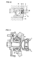
- a wheel bearing shown in Figs. 9 and 10 rotatably supports a rotating-side member such as a hub ring 25 supporting a wheel (driving wheel) consisting of a wheel 28 and a tire 29 with respect to a fixed-side member such as a knuckle 26.
- This wheel bearing mainly has an inner ring 21, an outer ring 22, a rolling element 23, a holder 24 and a sealing apparatus 30 including the magnetic encoder 3.
- the inner ring 21 is engaged with the outer peripheral surface of the hub ring 25, and the outer ring 22 is engaged with the inner peripheral surface of the knuckle 26.
- the rolling element 23 is held by the holder 24 to be capable of rolling between the inner ring 21 and the outer ring 22.
- the magnetic encoder 3 is press-fitted with an outer diametral portion of an end of the inner ring 21, while the magnetic member 1 multipolarly magnetized in the circumferential direction is closely opposed to a magnetic sensor 5 fixed to the knuckle 26.
- a fixed disk 31 is press-fitted with an inner diametral portion of the outer ring 22, and a sealing member 32 mounted on the fixed disk 31 is arranged to be capable of coming into sliding contact with the annular member 2.
- the magnetic encoder 3, the fixed disk 31 and the sealing member 32 form the sealing apparatus 30, and the magnetic encoder 3 also serves as a sealing slinger.
- the sealing apparatus 30 can prevent leakage of oil from the wheel bearing or penetration of foreign matter or moisture from outside the bearing.
- the magnetic encoder 3 is press-fitted in an outer diametral portion of the inner ring 21 to be located between two bearings.
- a magnetic sensor 5 is arranged between the two bearings to be closely opposed to the magnetic member 1 of the magnetic encoder 3.
- the magnetic encoder 3 is press-fitted with the outer periphery of the hub ring 25.
- a magnetic sensor 5 is mounted on a fixed-side member to be closely opposed to the magnetic member 1 of the magnetic encoder 3.
- the outer ring 22 is on the side of a rotating member and the inner ring 21 is on the side of a fixed member.
- the magnetic encoder 3 is press-fitted with an outer diametral portion of an end of the inner ring 21.
- a magnetic sensor 5 is arranged on a fixed member to be closely opposed to the magnetic member 1 of the magnetic encoder 3.
- the inner ring 21 is on the side of a rotating member
- the outer ring 22 is on the side of the fixed member.
- the inner ring 21 may be separate from or integrated with the hub ring 25.
- the outer ring 22 may be separate from or integrated with a knuckle 26.
- a sealing slinger used for the wheel bearing is preferably manufactured by press-molding a ferrite-based stainless steel plate of SUS430 or the like since a magnetic substance increases magnetic flux density as a back metal and has preservability.
- the magnetization pitch error can be reduced below 3 % similarly to that obtained in the surface layer magnetization while the surface magnetization strength can be increased to at least 30 mT/mm similarly to that obtained in the one-shot magnetization. Therefore, the magnetic encoder according to the present invention can detect a rotational frequency or the like with higher accuracy.
- the wheel bearing according to the present invention having the aforementioned magnetic encoder, can detect the speed of rotation of a wheel with high accuracy.
- the magnetization yoke holds and magnetizes the magnetic member so that the magnetic flux passes through the magnetic member, whereby magnetization strength can be increased to a level similar to that obtained in the one-shot magnetization. Further, each magnetic pole is magnetized and hence surface magnetization strength can be reduced to a level similar to that obtained in the surface layer magnetization so far as indexing accuracy of a spindle is attained.
Abstract
Description
| Comparison of Magnetization | ||||
| Magnetization Method Magnetization Method | Magnetization Pitch Error | Magnetization Strength | ||
| N Pole | S Pole | |||
| One-Shot Magnetization | ±3.5% | 77mT | 49mT | |
| Index | Surface Layer Magnetization | ±1.0% | 35mT | 35mT |
| Magnetization | Holding Method | ±1.0% | 77mT | 70mT |
Claims (9)
- A magnetic encoder comprising an annular member (2) and a magnetic member (1) circumferentially provided on said annular member (2) and multipolarly magnetized in the circumferential direction, wherein
a magnetization pitch error of said magnetic member (1) is not more than 3 % and surface magnetization strength per unit magnetic pole is at least 30 mT/mm. - The magnetic encoder according to claim 1, wherein said annular member (2) consists of a magnetic substance and said magnetic member (1) consists of an elastomer mixed with magnetic powder.
- A wheel bearing rotatably supporting a wheel (28, 29),
having a rotating member (25) provided with said magnetic encoder (3) according to claim 1, wherein said rotating member (25) is so arranged that said magnetic encoder (3) is closely opposed to a magnetic sensor (5) for detecting the speed of rotation of said wheel (28,29). - The wheel bearing according to claim 3, having a fixed member (26) rotatably supporting said rotating member (25), wherein said magnetic encoder (3) forms a sealing apparatus sealing an annular space between said rotating member (25) and said fixed member (26).
- The wheel bearing according to claim 4, wherein said sealing apparatus has a sealing member (32) mounted on said fixed member (26) to be capable of coming into sliding contact with said annular member (2) of said magnetic encoder (3).
- A method of manufacturing a magnetic encoder circumferentially providing a magnetic member (1) on an annular member (2) and magnetizing said magnetic member,
arranging a magnetization yoke (11) passing a magnetic flux for magnetizing said magnetic member (1) to hold said magnetic member (1) and said annular member (2) so that said magnetic flux passes through and magnetizes said magnetic member (1) in the portion held by said magnetization yoke (11) for successively magnetizing said magnetic member (1) along the circumferential direction thereby multipolarly magnetizing said magnetic member (1) in the circumferential direction. - The method of manufacturing a magnetic encoder according to claim 6, making magnetization conditions variable in N pole magnetization and S pole magnetization of the peripheral surface of said magnetic member (1).
- The method of manufacturing a magnetic encoder according to claim 7, varying the value of a current fed to a coil (12) wound on said magnetization yoke (11) with said N pole magnetization and said S pole magnetization.
- The method of manufacturing a magnetic encoder according to claim 7, varying the number of turns of a coil (12) wound on said magnetization yoke (11) with said N pole magnetization and said S pole magnetization.
Applications Claiming Priority (2)
| Application Number | Priority Date | Filing Date | Title |
|---|---|---|---|
| JP2000055798 | 2000-03-01 | ||
| JP2000055798A JP4018313B2 (en) | 2000-03-01 | 2000-03-01 | Manufacturing method of magnetic encoder |
Publications (3)
| Publication Number | Publication Date |
|---|---|
| EP1130362A2 true EP1130362A2 (en) | 2001-09-05 |
| EP1130362A3 EP1130362A3 (en) | 2004-01-02 |
| EP1130362B1 EP1130362B1 (en) | 2008-08-13 |
Family
ID=18576861
Family Applications (1)
| Application Number | Title | Priority Date | Filing Date |
|---|---|---|---|
| EP01104162A Expired - Lifetime EP1130362B1 (en) | 2000-03-01 | 2001-02-21 | Method of manufacturing a magnetic encoder |
Country Status (4)
| Country | Link |
|---|---|
| US (1) | US6570751B2 (en) |
| EP (1) | EP1130362B1 (en) |
| JP (1) | JP4018313B2 (en) |
| DE (1) | DE60135263D1 (en) |
Cited By (9)
| Publication number | Priority date | Publication date | Assignee | Title |
|---|---|---|---|---|
| EP1262780A2 (en) * | 2001-06-01 | 2002-12-04 | Koyo Seiko Co., Ltd. | Magnetizing apparatus and magnetizing method for magnetized pulser ring, and magnetized pulser ring |
| EP1447579A1 (en) * | 2001-11-22 | 2004-08-18 | NSK Ltd., | Sensor-equipped rolling bearing, and rotation state detecting device |
| EP1452870A1 (en) * | 2003-02-25 | 2004-09-01 | Ntn Corporation | Electrically powered brake system |
| FR2882140A1 (en) * | 2005-02-11 | 2006-08-18 | Electricfil Automotive Soc Par | POSITION SENSOR WITH COMPENSATED MAGNETIC POLES |
| WO2007057429A1 (en) * | 2005-11-18 | 2007-05-24 | Continental Teves Ag & Co. Ohg | Method for determining the encoder mapping error in the magnetic air gap of a wheel speed sensing system |
| WO2009112303A2 (en) * | 2008-03-10 | 2009-09-17 | Dr. Johannes Heidenhain Gmbh | Angle measuring system and method for producing an angle measuring system |
| WO2015090479A1 (en) * | 2013-12-20 | 2015-06-25 | Aktiebolaget Skf | Load determining system for a rolling element bearing |
| US10018524B2 (en) | 2014-12-16 | 2018-07-10 | Aktiebolaget Skf | Load determining system for a rolling element bearing |
| EP3985692A1 (en) * | 2020-10-14 | 2022-04-20 | Universität Wien | Writing head and method of writing a magnetization pattern |
Families Citing this family (22)
| Publication number | Priority date | Publication date | Assignee | Title |
|---|---|---|---|---|
| JP4209607B2 (en) * | 2000-09-05 | 2009-01-14 | Ntn株式会社 | Evaluation method of magnetized encoder |
| JP2003139787A (en) * | 2001-10-30 | 2003-05-14 | Mitsuba Corp | Rotating speed sensor and magnetizing method of permanent magnet used in rotating speed sensor |
| WO2004033995A1 (en) * | 2002-10-10 | 2004-04-22 | Koyo Seiko Co., Ltd. | Rolling bearing |
| US7249891B2 (en) * | 2002-10-28 | 2007-07-31 | Nsk Ltd. | Bearing device with sensor and rolling bearing with sensor |
| JP2004197879A (en) * | 2002-12-20 | 2004-07-15 | Uchiyama Mfg Corp | Seal with encoder |
| JP2005016569A (en) * | 2003-06-24 | 2005-01-20 | Nsk Ltd | Rolling bearing unit with encoder, and manufacturing method for the same |
| CN100385240C (en) * | 2003-09-16 | 2008-04-30 | Ntn株式会社 | Magnetic encoder and wheel support bearing assembly utilizing the same |
| US7318589B2 (en) * | 2003-09-22 | 2008-01-15 | Jtekt Corporation | Sealing device and rotation detector |
| EP2865999B1 (en) | 2004-01-22 | 2018-08-22 | NSK Ltd. | Magnetic encoder and bearing |
| JP2005233888A (en) * | 2004-02-23 | 2005-09-02 | Koyo Seiko Co Ltd | Method and equipment for manufacturing magnetic encoder |
| JP4803786B2 (en) * | 2004-06-30 | 2011-10-26 | 内山工業株式会社 | Magnetizing method and apparatus for tone wheel |
| JP2006057814A (en) * | 2004-08-24 | 2006-03-02 | Ntn Corp | Bearing device for wheel |
| JP2006105341A (en) * | 2004-10-08 | 2006-04-20 | Ntn Corp | Bearing for wheel integrated with speed sensor exclusively used for motorcycle |
| DE102005049559A1 (en) * | 2005-10-12 | 2007-04-19 | Bogen Electronic Gmbh | Magnet code applying method for magnetizable layers of e.g. scale, involves coding magnetizable layer, measuring realization accuracy of coding, computing correction value, and establishing further coding based on computed value |
| JP2007232606A (en) * | 2006-03-02 | 2007-09-13 | Ntn Corp | Bearing for wheel |
| JP5144960B2 (en) * | 2007-05-28 | 2013-02-13 | 日本精工株式会社 | Magnetizing method and magnetizing apparatus for encoder |
| JP5085982B2 (en) * | 2007-06-08 | 2012-11-28 | 日本精工株式会社 | Magnetizing method and magnetizing apparatus for encoder |
| JP5035541B2 (en) * | 2007-12-04 | 2012-09-26 | Nok株式会社 | Pulsar ring for magnetic encoder |
| DE102007063006A1 (en) * | 2007-12-21 | 2009-06-25 | Baumer Holding Ag | Method and device for producing a material measure for position measuring systems and material measure |
| WO2011125191A1 (en) | 2010-04-07 | 2011-10-13 | 株式会社アドバンテスト | Probe and manufacturing method for same |
| JP6382503B2 (en) | 2013-11-12 | 2018-08-29 | 内山工業株式会社 | Magnetizing apparatus and magnetizing method for magnet for magnetic encoder |
| DE102020206479A1 (en) * | 2020-05-25 | 2021-11-25 | Aktiebolaget Skf | Method for manufacturing a sensor bearing unit |
Citations (8)
| Publication number | Priority date | Publication date | Assignee | Title |
|---|---|---|---|---|
| DE2361154A1 (en) * | 1972-12-07 | 1974-06-12 | Yamauchi Rubber Ind Co Ltd | DEVICE FOR MULTIPOLAR MAGNETIZATION |
| EP0027308A1 (en) * | 1979-08-16 | 1981-04-22 | Inoue-Japax Research Incorporated | Manufacture and use of magnetic scale systems |
| DE3214176A1 (en) * | 1982-04-17 | 1983-10-20 | Erich Dr.-Ing. 5300 Bonn Steingroever | MULTIPOLE MAGNETIZING DEVICE FOR PERMANENT MAGNET |
| US5089817A (en) * | 1989-09-18 | 1992-02-18 | The Torrington Company | High resolution encoder |
| US5143458A (en) * | 1990-04-13 | 1992-09-01 | The Torrington Company | Bearing with rolling elements equipped with an adjustable information pickup device |
| US5431413A (en) * | 1993-01-19 | 1995-07-11 | The Torrington Company | Seal incorporating an encoder |
| EP0836020A2 (en) * | 1996-10-11 | 1998-04-15 | Nsk Ltd | Rolling bearing unit with rotating speed sensor |
| US5984745A (en) * | 1997-08-04 | 1999-11-16 | U.S. Philips Corporation | Method of manufacturing a magnetic device |
Family Cites Families (17)
| Publication number | Priority date | Publication date | Assignee | Title |
|---|---|---|---|---|
| US2496103A (en) * | 1944-09-14 | 1950-01-31 | Neufeld Jacob | Indexing and speed control system for magnetic reproducers |
| US3293636A (en) * | 1963-07-22 | 1966-12-20 | Unimation Inc | Magnetic flux responsive sensing device |
| JPH0297261A (en) * | 1988-09-30 | 1990-04-09 | Sony Corp | Magnetization pattern for motor magnet |
| US5117183A (en) * | 1990-02-21 | 1992-05-26 | The Torrington Company | Asymmetric magnetization fixture |
| JP2816783B2 (en) | 1992-02-26 | 1998-10-27 | 内山工業株式会社 | Bearing seal with rotation detection device |
| JPH0682819U (en) * | 1993-04-30 | 1994-11-25 | 三菱マテリアル株式会社 | Magnetizing device |
| US5545985A (en) * | 1994-03-16 | 1996-08-13 | Campbell; Peter | Magnetoresistive position sensor including an encoder wherein the magnetization extends greater than 0.5 times the pole pitch below the surface |
| DE19534995A1 (en) * | 1995-09-21 | 1997-03-27 | Bosch Gmbh Robert | Steering wheel angle sensor |
| JP3653885B2 (en) * | 1996-10-11 | 2005-06-02 | 日本精工株式会社 | Magnetizer for encoder for rotational speed detector |
| JPH10253646A (en) * | 1997-03-07 | 1998-09-25 | Nippon Seiko Kk | Sensor mounting part for rolling bearing unit with rotational-speed detecting device |
| JPH10300514A (en) * | 1997-04-25 | 1998-11-13 | Hitachi Metals Ltd | Magnetic scale and its writing method |
| JPH116744A (en) * | 1997-06-16 | 1999-01-12 | Sankyo Seiki Mfg Co Ltd | Encoder device |
| JP3968857B2 (en) * | 1998-01-09 | 2007-08-29 | 日本精工株式会社 | Seal structure of rotation speed detector |
| JP3451423B2 (en) * | 1998-02-25 | 2003-09-29 | 内山工業株式会社 | How to magnetize the tone wheel |
| JPH11264739A (en) * | 1998-03-17 | 1999-09-28 | Yazaki Corp | Rotation detector |
| US6471521B1 (en) * | 1998-07-31 | 2002-10-29 | Athenium, L.L.C. | System for implementing collaborative training and online learning over a computer network and related techniques |
| US20010031456A1 (en) * | 1999-12-30 | 2001-10-18 | Greg Cynaumon | Education system and method for providing educational exercises and establishing an educational fund |
-
2000
- 2000-03-01 JP JP2000055798A patent/JP4018313B2/en not_active Expired - Lifetime
-
2001
- 2001-02-20 US US09/785,468 patent/US6570751B2/en not_active Expired - Lifetime
- 2001-02-21 DE DE60135263T patent/DE60135263D1/en not_active Expired - Lifetime
- 2001-02-21 EP EP01104162A patent/EP1130362B1/en not_active Expired - Lifetime
Patent Citations (8)
| Publication number | Priority date | Publication date | Assignee | Title |
|---|---|---|---|---|
| DE2361154A1 (en) * | 1972-12-07 | 1974-06-12 | Yamauchi Rubber Ind Co Ltd | DEVICE FOR MULTIPOLAR MAGNETIZATION |
| EP0027308A1 (en) * | 1979-08-16 | 1981-04-22 | Inoue-Japax Research Incorporated | Manufacture and use of magnetic scale systems |
| DE3214176A1 (en) * | 1982-04-17 | 1983-10-20 | Erich Dr.-Ing. 5300 Bonn Steingroever | MULTIPOLE MAGNETIZING DEVICE FOR PERMANENT MAGNET |
| US5089817A (en) * | 1989-09-18 | 1992-02-18 | The Torrington Company | High resolution encoder |
| US5143458A (en) * | 1990-04-13 | 1992-09-01 | The Torrington Company | Bearing with rolling elements equipped with an adjustable information pickup device |
| US5431413A (en) * | 1993-01-19 | 1995-07-11 | The Torrington Company | Seal incorporating an encoder |
| EP0836020A2 (en) * | 1996-10-11 | 1998-04-15 | Nsk Ltd | Rolling bearing unit with rotating speed sensor |
| US5984745A (en) * | 1997-08-04 | 1999-11-16 | U.S. Philips Corporation | Method of manufacturing a magnetic device |
Cited By (20)
| Publication number | Priority date | Publication date | Assignee | Title |
|---|---|---|---|---|
| EP1262780A2 (en) * | 2001-06-01 | 2002-12-04 | Koyo Seiko Co., Ltd. | Magnetizing apparatus and magnetizing method for magnetized pulser ring, and magnetized pulser ring |
| EP1262780A3 (en) * | 2001-06-01 | 2004-05-12 | Koyo Seiko Co., Ltd. | Magnetizing apparatus and magnetizing method for magnetized pulser ring, and magnetized pulser ring |
| EP1447579A1 (en) * | 2001-11-22 | 2004-08-18 | NSK Ltd., | Sensor-equipped rolling bearing, and rotation state detecting device |
| EP1447579A4 (en) * | 2001-11-22 | 2006-04-12 | Nsk Ltd | Sensor-equipped rolling bearing, and rotation state detecting device |
| US7290938B2 (en) | 2001-11-22 | 2007-11-06 | Nsk Ltd. | Sensor-equipped rolling bearing, and rotation state detecting device |
| US7481583B2 (en) | 2001-11-22 | 2009-01-27 | Nsk Ltd. | Rolling bearing with sensor and rotary state detecting device |
| EP1452870A1 (en) * | 2003-02-25 | 2004-09-01 | Ntn Corporation | Electrically powered brake system |
| FR2882140A1 (en) * | 2005-02-11 | 2006-08-18 | Electricfil Automotive Soc Par | POSITION SENSOR WITH COMPENSATED MAGNETIC POLES |
| US7265685B2 (en) | 2005-02-11 | 2007-09-04 | Electricfil Automotive | Position sensor with compensated magnetic poles |
| WO2007057429A1 (en) * | 2005-11-18 | 2007-05-24 | Continental Teves Ag & Co. Ohg | Method for determining the encoder mapping error in the magnetic air gap of a wheel speed sensing system |
| WO2009112303A2 (en) * | 2008-03-10 | 2009-09-17 | Dr. Johannes Heidenhain Gmbh | Angle measuring system and method for producing an angle measuring system |
| WO2009112303A3 (en) * | 2008-03-10 | 2010-01-28 | Dr. Johannes Heidenhain Gmbh | Angle measuring system and method for producing an angle measuring system |
| CN101965519B (en) * | 2008-03-10 | 2013-03-06 | 约翰尼斯海登海恩博士股份有限公司 | Angle measuring system and method for producing an angle measuring system |
| US8664944B2 (en) | 2008-03-10 | 2014-03-04 | Dr. Johannes Heidenhain Gmbh | Angle measuring system and method for producing an angle measuring system |
| WO2015090479A1 (en) * | 2013-12-20 | 2015-06-25 | Aktiebolaget Skf | Load determining system for a rolling element bearing |
| US20160334290A1 (en) * | 2013-12-20 | 2016-11-17 | Aktiebolaget Skf | Load determining system for a rolling element bearing |
| US10508960B2 (en) | 2013-12-20 | 2019-12-17 | Aktiebolaget Skf | Load determining system for a rolling element bearing |
| US10018524B2 (en) | 2014-12-16 | 2018-07-10 | Aktiebolaget Skf | Load determining system for a rolling element bearing |
| EP3985692A1 (en) * | 2020-10-14 | 2022-04-20 | Universität Wien | Writing head and method of writing a magnetization pattern |
| WO2022079131A1 (en) * | 2020-10-14 | 2022-04-21 | Universitaet Wien | Writing head and method of writing a magnetization pattern |
Also Published As
| Publication number | Publication date |
|---|---|
| US6570751B2 (en) | 2003-05-27 |
| DE60135263D1 (en) | 2008-09-25 |
| JP4018313B2 (en) | 2007-12-05 |
| EP1130362B1 (en) | 2008-08-13 |
| US20010030533A1 (en) | 2001-10-18 |
| EP1130362A3 (en) | 2004-01-02 |
| JP2001242187A (en) | 2001-09-07 |
Similar Documents
| Publication | Publication Date | Title |
|---|---|---|
| EP1130362B1 (en) | Method of manufacturing a magnetic encoder | |
| US4803885A (en) | Torque measuring apparatus | |
| US5239263A (en) | Magnetic rotation sensor for rotary shaft | |
| JP2003254985A (en) | Rolling bearing unit having rotating speed detecting device | |
| JP3862302B2 (en) | Rolling bearing unit with rotational speed detector | |
| US4969753A (en) | Wheel bearing assembly for automotive wheel | |
| JP2022164765A (en) | Magnetic encoder and manufacturing method therefor | |
| CN109256905A (en) | Toroidal magnet for rotor position estimate | |
| US20190346292A1 (en) | Magnetic encoder, and method and device for producing same | |
| JP6937128B2 (en) | Magnetic encoder and its manufacturing method | |
| US20110304324A1 (en) | Magnetic encoder | |
| US6927705B2 (en) | Magnetic rubber encoder | |
| US20220034366A1 (en) | Method for mounting a sensor bearing unit, and sensor bearing unit adapted to such a method | |
| JP3653885B2 (en) | Magnetizer for encoder for rotational speed detector | |
| US11378131B2 (en) | Method for manufacturing a sensor bearing unit | |
| JP3979058B2 (en) | Encoder inspection method and inspection magnetizing apparatus | |
| KR102419301B1 (en) | Absolute position detection device and detection method of rotating body | |
| US20200141765A1 (en) | Magnetic Encoder and Apparatus Having the Same | |
| JP2004293622A (en) | Rolling bearing unit having encoder and its manufacturing method | |
| JP4225002B2 (en) | Positioning jig for detected body of rolling bearing device and method of manufacturing rolling bearing device | |
| JP3700291B2 (en) | Rolling bearing unit with rotational speed detector | |
| JPH0587822A (en) | Rotational speed detecting device for rolling bearing | |
| US20200141761A1 (en) | Magnetic Encoder and Apparatus Having the Same | |
| CN110873583A (en) | Magnetic encoder for measuring deflection of rotating shaft and device thereof | |
| JP2003184901A (en) | Method of manufacturing bearing with pulser ring |
Legal Events
| Date | Code | Title | Description |
|---|---|---|---|
| PUAI | Public reference made under article 153(3) epc to a published international application that has entered the european phase |
Free format text: ORIGINAL CODE: 0009012 |
|
| AK | Designated contracting states |
Kind code of ref document: A2 Designated state(s): AT BE CH CY DE DK ES FI FR GB GR IE IT LI LU MC NL PT SE TR |
|
| AX | Request for extension of the european patent |
Free format text: AL;LT;LV;MK;RO;SI |
|
| PUAL | Search report despatched |
Free format text: ORIGINAL CODE: 0009013 |
|
| AK | Designated contracting states |
Kind code of ref document: A3 Designated state(s): AT BE CH CY DE DK ES FI FR GB GR IE IT LI LU MC NL PT SE TR |
|
| AX | Request for extension of the european patent |
Extension state: AL LT LV MK RO SI |
|
| RIC1 | Information provided on ipc code assigned before grant |
Ipc: 7H 01F 13/00 B Ipc: 7G 01D 5/243 A |
|
| 17P | Request for examination filed |
Effective date: 20040621 |
|
| 17Q | First examination report despatched |
Effective date: 20040729 |
|
| AKX | Designation fees paid |
Designated state(s): DE FR |
|
| RTI1 | Title (correction) |
Free format text: METHOD OF MANUFACTURING A MAGNETIC ENCODER |
|
| GRAP | Despatch of communication of intention to grant a patent |
Free format text: ORIGINAL CODE: EPIDOSNIGR1 |
|
| GRAS | Grant fee paid |
Free format text: ORIGINAL CODE: EPIDOSNIGR3 |
|
| GRAA | (expected) grant |
Free format text: ORIGINAL CODE: 0009210 |
|
| AK | Designated contracting states |
Kind code of ref document: B1 Designated state(s): DE FR |
|
| REF | Corresponds to: |
Ref document number: 60135263 Country of ref document: DE Date of ref document: 20080925 Kind code of ref document: P |
|
| PLBE | No opposition filed within time limit |
Free format text: ORIGINAL CODE: 0009261 |
|
| STAA | Information on the status of an ep patent application or granted ep patent |
Free format text: STATUS: NO OPPOSITION FILED WITHIN TIME LIMIT |
|
| 26N | No opposition filed |
Effective date: 20090514 |
|
| REG | Reference to a national code |
Ref country code: FR Ref legal event code: PLFP Year of fee payment: 15 |
|
| REG | Reference to a national code |
Ref country code: FR Ref legal event code: PLFP Year of fee payment: 16 |
|
| REG | Reference to a national code |
Ref country code: FR Ref legal event code: PLFP Year of fee payment: 17 |
|
| REG | Reference to a national code |
Ref country code: FR Ref legal event code: PLFP Year of fee payment: 18 |
|
| PGFP | Annual fee paid to national office [announced via postgrant information from national office to epo] |
Ref country code: DE Payment date: 20200211 Year of fee payment: 20 |
|
| PGFP | Annual fee paid to national office [announced via postgrant information from national office to epo] |
Ref country code: FR Payment date: 20200113 Year of fee payment: 20 |
|
| REG | Reference to a national code |
Ref country code: DE Ref legal event code: R071 Ref document number: 60135263 Country of ref document: DE |