EP1130294A2 - Surface following brush seal - Google Patents
Surface following brush seal Download PDFInfo
- Publication number
- EP1130294A2 EP1130294A2 EP01301821A EP01301821A EP1130294A2 EP 1130294 A2 EP1130294 A2 EP 1130294A2 EP 01301821 A EP01301821 A EP 01301821A EP 01301821 A EP01301821 A EP 01301821A EP 1130294 A2 EP1130294 A2 EP 1130294A2
- Authority
- EP
- European Patent Office
- Prior art keywords
- carrier
- holder
- brush seal
- seal
- tang
- Prior art date
- Legal status (The legal status is an assumption and is not a legal conclusion. Google has not performed a legal analysis and makes no representation as to the accuracy of the status listed.)
- Granted
Links
Images


Classifications
-
- F—MECHANICAL ENGINEERING; LIGHTING; HEATING; WEAPONS; BLASTING
- F01—MACHINES OR ENGINES IN GENERAL; ENGINE PLANTS IN GENERAL; STEAM ENGINES
- F01D—NON-POSITIVE DISPLACEMENT MACHINES OR ENGINES, e.g. STEAM TURBINES
- F01D11/00—Preventing or minimising internal leakage of working-fluid, e.g. between stages
- F01D11/02—Preventing or minimising internal leakage of working-fluid, e.g. between stages by non-contact sealings, e.g. of labyrinth type
-
- F—MECHANICAL ENGINEERING; LIGHTING; HEATING; WEAPONS; BLASTING
- F16—ENGINEERING ELEMENTS AND UNITS; GENERAL MEASURES FOR PRODUCING AND MAINTAINING EFFECTIVE FUNCTIONING OF MACHINES OR INSTALLATIONS; THERMAL INSULATION IN GENERAL
- F16J—PISTONS; CYLINDERS; SEALINGS
- F16J15/00—Sealings
- F16J15/16—Sealings between relatively-moving surfaces
- F16J15/32—Sealings between relatively-moving surfaces with elastic sealings, e.g. O-rings
- F16J15/3204—Sealings between relatively-moving surfaces with elastic sealings, e.g. O-rings with at least one lip
- F16J15/3224—Sealings between relatively-moving surfaces with elastic sealings, e.g. O-rings with at least one lip capable of accommodating changes in distances or misalignment between the surfaces, e.g. able to compensate for defaults of eccentricity or angular deviations
-
- F—MECHANICAL ENGINEERING; LIGHTING; HEATING; WEAPONS; BLASTING
- F16—ENGINEERING ELEMENTS AND UNITS; GENERAL MEASURES FOR PRODUCING AND MAINTAINING EFFECTIVE FUNCTIONING OF MACHINES OR INSTALLATIONS; THERMAL INSULATION IN GENERAL
- F16J—PISTONS; CYLINDERS; SEALINGS
- F16J15/00—Sealings
- F16J15/16—Sealings between relatively-moving surfaces
- F16J15/32—Sealings between relatively-moving surfaces with elastic sealings, e.g. O-rings
- F16J15/3284—Sealings between relatively-moving surfaces with elastic sealings, e.g. O-rings characterised by their structure; Selection of materials
- F16J15/3288—Filamentary structures, e.g. brush seals
-
- F—MECHANICAL ENGINEERING; LIGHTING; HEATING; WEAPONS; BLASTING
- F05—INDEXING SCHEMES RELATING TO ENGINES OR PUMPS IN VARIOUS SUBCLASSES OF CLASSES F01-F04
- F05D—INDEXING SCHEME FOR ASPECTS RELATING TO NON-POSITIVE-DISPLACEMENT MACHINES OR ENGINES, GAS-TURBINES OR JET-PROPULSION PLANTS
- F05D2240/00—Components
- F05D2240/55—Seals
- F05D2240/56—Brush seals
-
- F—MECHANICAL ENGINEERING; LIGHTING; HEATING; WEAPONS; BLASTING
- F05—INDEXING SCHEMES RELATING TO ENGINES OR PUMPS IN VARIOUS SUBCLASSES OF CLASSES F01-F04
- F05D—INDEXING SCHEME FOR ASPECTS RELATING TO NON-POSITIVE-DISPLACEMENT MACHINES OR ENGINES, GAS-TURBINES OR JET-PROPULSION PLANTS
- F05D2300/00—Materials; Properties thereof
- F05D2300/50—Intrinsic material properties or characteristics
- F05D2300/501—Elasticity
-
- Y—GENERAL TAGGING OF NEW TECHNOLOGICAL DEVELOPMENTS; GENERAL TAGGING OF CROSS-SECTIONAL TECHNOLOGIES SPANNING OVER SEVERAL SECTIONS OF THE IPC; TECHNICAL SUBJECTS COVERED BY FORMER USPC CROSS-REFERENCE ART COLLECTIONS [XRACs] AND DIGESTS
- Y02—TECHNOLOGIES OR APPLICATIONS FOR MITIGATION OR ADAPTATION AGAINST CLIMATE CHANGE
- Y02T—CLIMATE CHANGE MITIGATION TECHNOLOGIES RELATED TO TRANSPORTATION
- Y02T50/00—Aeronautics or air transport
- Y02T50/60—Efficient propulsion technologies, e.g. for aircraft
Definitions
- This invention relates generally to brush seals and more particularly to brush seals for use in gas turbine engines.
- a gas turbine engine operates according to well known principles wherein an incoming stream of atmospheric air flows through the engine along an axially extending flow path. At least a portion of the incoming air is compressed in a compressor section of the engine and then mixed with fuel and burned in a combustor section to produce a high energy, high temperature exhaust gas stream. The hot gas stream exits the combustor and subsequently passes through a turbine section that extracts energy from the exhaust gas stream to power the compressor and provide useful work such as powering an aircraft in flight.
- a conventional brush seal typically includes a bristle pack having a plurality of bristles disposed between a pair of annular plates.
- the bristles usually are disposed at about a forty five degree angle to a radius drawn from the engine centerline.
- a brush seal is typically attached along its outer radial edge to a stationary engine part with the radially inner, free ends of the bristles disposed in a sealing engagement with a sealing surface on a rotating engine part.
- Brush seals are not intended to function so as to completely seal one engine section from another, but rather rely upon the tortuous flow path created between the bristles to reduce gas flow therethrough and to control the pressure drop between the engine sections.
- the bristles in the bristle pact are somewhat flexible and are thus able to bend during an engine transient and still retain their sealing ability after the transient has passed.
- transients include differential thermal growth between the stationary and rotating engine parts and relative lateral motion between the stationary and rotating engine parts due to engine vibrations and/or eccentric shaft rotation.
- the sealing efficiency of a brush seal over time is affected by the wear on the bristle ends contacting the sealing surface on the rotating engine part, as well as the overall contact of the bristle ends with the sealing surface.
- the relative lateral motion between the engine parts can be of a magnitude large enough to cause significant bristle flexure, which leads to premature and excessive wear on the bristles.
- Premature bristle wear will require replacement of the seal or bristle pack earlier than otherwise would be necessary, thereby increasing engine operating costs.
- the present invention provides a brush seal having a holder and a carrier moveably suspended from the holder by a plurality of flexible support wires.
- a plurality of bristles is secured to the carrier.
- the holder is attached to a stationary member, and the bristles sealingly engage a rotating member.
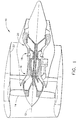
- the present invention is described relative to one possible application in an aircraft gas turbine engine 10, which is shown in Figure 1.
- the engine 10 is a high bypass ratio turbofan engine that includes, in serial axial flow communication about a longitudinal centerline axis 12, a fan 14, a compressor section 16, a combustor section 18, and a turbine section 20.
- An incoming air stream enters the engine 10 with a portion thereof flowing through a bypass duct 22 to produce bypass thrust.
- the remaining portion of the air stream enters the compressor section 16.
- This air is compressed in the compressor section 16 and passed to the combustor section 18 where it is mixed with fuel, and the air/fuel mixture is ignited.
- the ignited air/fuel mixture produces a high-temperature gas stream that passes through the turbine section 20.
- the turbine section 20 extracts energy from the hot gas stream and uses the energy to power the compressor section 16 and the fan 14 that generates the aforementioned bypass thrust.
- the turbine section 20 includes a plurality of circumferential rows of substantially radially directed rotor blades 24 interdigitated with one or more circumferential rows of substantially radially extending stator vanes 26.
- the rotor blades 24 of each row are mounted to a rotor disk 28.
- the rotor disks 28 are in turn rigidly connected to a rotating turbine shaft 30 via a turbine shaft cone 32 for rotation about the engine's centerline axis 12 (not shown in Figure 2).
- the turbine section 20 further includes a number of brush seals 34 that are interposed between stationary engine structural members or seal supports 36 and rotating members 38 that are rigidly attached to the turbine shaft cone 32 for rotation therewith.
- the rotating members 38 are generally cylindrical in form and are partially located within the corresponding one of the seal supports 36, which are also generally cylindrical in form.
- each brush seal 34 includes a plurality of bristles that extends from a fixed connection with the respective seal support 36 to a sealing engagement with the corresponding rotating member 38.
- the brush seals 34 are positioned in the turbine section 20 so as to prevent undesired leakage of gases, such as cooling air at different pressures, from one cavity to another within the engine 10.
- gases such as cooling air at different pressures
- the brush seal 34 is disposed in an annular gap between the seal support 36 and the rotating member 38.
- both the seal support 36 and the rotating member 38 are generally cylindrical in form, and the stationary seal support 36 surrounds the forward end of the rotating member 38 so as to define the aforementioned annular gap.
- the rotating member 38 is joined to the turbine shaft cone 32 (not shown in Figure 3) via a flange 39 formed on the aft end thereof.
- the annular gap forms a leakage path between a first cavity 40 and a second cavity 41.
- the first cavity 40 is at a higher pressure than the second cavity 41 so that any flow through the gap would be in the direction indicated by arrow A in Figure 3.
- the brush seal 34 includes an annular holder 42 that is disposed coaxially with respect to the centerline axis 12 in a seal pocket 44 formed on the aft end of the seal support 36.
- the seal pocket 44 is shown as being disposed on the aft end of the seal support 36, it should be noted that the present invention is not limited to this configuration. A seal pocket could also be located on the forward end of the seal support, depending on the configuration of the particular seal support-rotating member combination to be sealed.
- the seal pocket 44 includes a radially oriented wall 46 and an axially oriented wall 48.
- a mounting flange 50 extends radially outward from the distal end of the axial wall 48.
- the holder 42 is attached to the seal support 36 by a retainer plate 52.
- the retainer plate 52 is an annular member fixedly secured to the mounting flange 50 by conventional fasteners 54 so that it firmly engages the holder 42 for retention in the seal pocket 44 via a pressure fit.
- An annular carrier 56 is disposed radially within the holder 42 and moveably suspended from the holder 42 by a plurality of axially-oriented, flexible support wires 58 (only one shown in Figure 3). Because the support wires 58 are flexible, the carrier 56 is able to move radially with respect to the engine's centerline axis 12 (not shown in Figure 3).
- the brush seal 34 further includes a bristle pack comprising a plurality of bristles 59 disposed around the circumference of the carrier 56.
- the radially outermost ends of the bristles 59 are secured to the carrier 56, and the radially inner, free ends engage the outer surface of the rotating member 38, thereby sealing the leakage path between the first and second cavities 40 and 41.
- the bristles 59 are somewhat flexible and are thus able to withstand relative movement in the radial and axial directions that may occur during an engine transient and still retain their sealing ability after the transient has passed.
- the carrier 56 is moveably suspended from the holder 42, the free ends of the bristles 59 are able to follow the outer surface of the rotating member 38 during engine transients. This reduces bristle flexure, which in turn reduces bristle wear.
- the carrier 56 comprises an annular body portion 60 having an axially aft extending flange 62 formed on the radially outer end thereof.
- the bristles 59 are sandwiched between the annular body portion 60 and an annular front plate 63 disposed on the high pressure side of the brush seal 34.
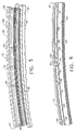
- the flange 62 has a number of pockets 64 formed in the aft face thereof. As best seen in Figures 4 and 6, the pockets 64 are distributed about the circumference of the flange 62 with narrow spaces therebetween. The pockets 64 reduce the mass of the carrier 56 so that it will move quickly in response to lateral motion of the rotating member 38 relative to the seal support 36.
- the flange 62 also has a number of holes 66 formed between adjacent pockets 64 for receiving an end of a corresponding one of the support wires 58.
- one of the holes 66 is formed in each space between adjacent pockets 64 except one.
- the other space between adjacent pockets 64 is provided with a slot 68, as shown in Figure 6, which extends through the radial thickness of the flange 62.
- the holder 42 comprises a cylindrical body portion 70 having a radially inward extending flange 72 formed on the aft end thereof.
- the flange 72 has a number of holes 74 formed therein for receiving the other end of the corresponding support wires 58.
- the forward edge 76 of the cylindrical body portion 70 abuts the radial wall 46 to axially position the holder 42 in the seal pocket 44.
- the holder 42 is preferably somewhat longer axially than the axial wall 48 to assure proper loading thereof when engaged by the retainer plate 52.
- the inside diameter of the cylindrical body portion 70 is greater than the outside diameter of the carrier 56 so as to provide a radial clearance between the carrier 56 and the cylindrical body portion 70.
- An anti-rotation tang 78 extends radially inward from the cylindrical body portion 70, near to, but spaced from, the forward edge 76.
- the anti-rotation tang 78 is received within the slot 68 so as to engage the carrier 56 and prevent rotation of the carrier 56 with respect to the holder 42.
- the anti-rotation tang 78 is sufficiently thick (on the order of 0.25 inches) to allow for fatigue life.
- a flexible link 80 is disposed in the slot 68 between the carrier 56 and the anti-rotation tang 78.
- the flexible link 80 is in the form of a metal band attached at one end to the carrier 56 and extends circumferentially to engage the anti-rotation tang 78.
- the flexible link 80 thus reduces friction between the carrier 56 and the anti-rotation tang 78 as the carrier 56 slides radially due to lateral motion of the rotating member 38 relative to the seal support 36.
- the flexible link 80 is disposed on the pressure side of the anti-rotation tang 78, i.e., the side of the anti-rotation tang 78 against which the carrier 56 reacts against due to rotation of the rotating member 38.
- the flexible link 80 could be omitted, and the width of the slot 68 would be just slightly larger than the width of the anti-rotation tang 78.
- each support wire 58 extends axially from one of the holes 66 formed in the carrier flange 62 to a corresponding one of the holes 74 formed in the holder flange 72.
- the opposite ends of each support wire 58 are welded or otherwise fixed to the carrier flange 62 and the holder flange 72, respectively.
- the holes 66 and 74 are tapered such that the load supported by the support wires 58 is distributed over the entire thicknesses or lengths of the carrier flange 62 and the holder flange 72, respectively.
- the aft ends of the holes 66 have a larger opening than the forward ends thereof, and the forward ends of the holes 74 have a larger opening than the aft ends thereof.
- the support wires 58 are equally spaced circumferentially, and the number of support wires 58 utilized should be sufficient to support the carrier 56. Preferably, enough support wires 58 are used to assure continued viability of the brush seal 34 should some of the support wires 58 fail. Typically, at least 10 support wires 58 will be used.
- the length of the support wires 58 is such so as to position the carrier 56 very close to, but not touching, the radial wall 46 of the seal pocket 44. This provides a narrow axial gap between the carrier 56 and the radial wall 46 so that these two elements do not rub together as the carrier 56 moves radially due to lateral motion of the rotating member 38 relative to the seal support 36.
- the support wires 58 also position the carrier 56 radially so as to leave a sufficient clearance between the radially outer edge of the carrier 56 and the cylindrical body portion 70 of the holder 42 to accommodate radial motion of the carrier 56. Axially aft motion of the carrier 56 is constrained by the axial rigidity of the support wires 58 and the anti-rotation tang 78.
- the axial gap between the carrier 56 and the radial wall 46 creates a leakage path between the first and second cavities 40 and 41.
- a plurality of concentric grooves 82 is formed in the forward surface of the annular body portion 60 of the carrier 56, facing the radial wall 46. The grooves 82, and the lands formed therebetween, consequently function as a labyrinth seal between the carrier 56 and the radial wall 46, thereby sealing the leakage path through the narrow axial gap.
Landscapes
- Engineering & Computer Science (AREA)
- General Engineering & Computer Science (AREA)
- Mechanical Engineering (AREA)
- Sealing Devices (AREA)
- Turbine Rotor Nozzle Sealing (AREA)
- Brushes (AREA)
Abstract
Description
Claims (10)
- A brush seal (34) comprising:a holder (42);a carrier (56) moveably suspended from said holder (42) by a plurality of flexible support wires (58); anda plurality of bristles (59) secured to said carrier (56).
- The brush seal (34) of claim 1 further comprising a slot (68) formed in one of said carrier (56) or said holder (42), and a tang (78) formed on the other of said carrier (56) or said holder (42), said tang (78) being received in said slot (68).
- The brush seal (34) of claim 1 wherein said carrier (56) has a flange (62) formed thereon, said flange (62) having a slot (68) formed therein, and a tang (78) formed on said holder (42), said tang (78) being received in said slot (68).
- A brush seal (34) for sealing a leakage path located between a stationary member (36) and a rotating member (38) that rotates about an axis (12), said brush seal (34) comprising:an annular holder (42) disposed coaxially about said axis (12) and attached to said stationary member (36);an annular carrier (56) disposed within said holder (42) and moveably suspended from said holder (42) by a plurality of flexible support wires (58); anda plurality of bristles (59) secured to said carrier (56) and sealingly engaging said rotating member (38).
- The brush seal (34) of claim 1 or claim 4 wherein said holder (42) is disposed in a seal pocket (44) formed in said stationary member (36).
- The brush seal (34) of claim 4 wherein said holder (42) defines an inside diameter and said carrier (56) defines an outside diameter that is less than said inside diameter so as to provide a clearance between said holder (42) and said carrier (56).
- The brush seal (34) of claim 4 wherein said carrier (56) has a flange (62) formed thereon, said flange (62) extending axially with respect to said axis (12).
- The brush seal (34) of claim 1 or claim 4 wherein a first end of each support wire (58) is received in a corresponding one of a plurality of holes (72) formed in said holder (42), and a second end of each support wire (58) is received in a corresponding one of a plurality of holes (66) formed in said carrier (56).
- The brush seal (34) of claim 8 wherein said holes (72) formed in said holder (42) and said holes (66) formed in said carrier (56) are tapered.
- The brush seal (34) of claim 4 wherein said support wires (58) are oriented axially with respect to said axis (12).
Applications Claiming Priority (2)
| Application Number | Priority Date | Filing Date | Title |
|---|---|---|---|
| US515258 | 2000-02-29 | ||
| US09/515,258 US6540231B1 (en) | 2000-02-29 | 2000-02-29 | Surface following brush seal |
Publications (3)
| Publication Number | Publication Date |
|---|---|
| EP1130294A2 true EP1130294A2 (en) | 2001-09-05 |
| EP1130294A3 EP1130294A3 (en) | 2003-05-28 |
| EP1130294B1 EP1130294B1 (en) | 2005-10-26 |
Family
ID=24050612
Family Applications (1)
| Application Number | Title | Priority Date | Filing Date |
|---|---|---|---|
| EP01301821A Expired - Lifetime EP1130294B1 (en) | 2000-02-29 | 2001-02-28 | Surface following brush seal |
Country Status (4)
| Country | Link |
|---|---|
| US (1) | US6540231B1 (en) |
| EP (1) | EP1130294B1 (en) |
| JP (1) | JP2001355737A (en) |
| DE (1) | DE60114264T2 (en) |
Cited By (10)
| Publication number | Priority date | Publication date | Assignee | Title |
|---|---|---|---|---|
| EP1375983A3 (en) * | 2002-06-27 | 2004-03-10 | United Technologies Corporation | Replaceable brush seal elements |
| EP1517006A1 (en) * | 2003-09-19 | 2005-03-23 | Snecma Moteurs | Gas turbine brush seal arrangement for cabin air supply |
| GB2407626A (en) * | 2003-10-31 | 2005-05-04 | Rolls Royce Plc | Suspended seal arrangement |
| WO2005061932A1 (en) * | 2003-12-22 | 2005-07-07 | Ebara Corporation | Seal mechanism for fluid machine |
| EP1420145A3 (en) * | 2002-11-15 | 2006-08-30 | Rolls-Royce Plc | Sealing arrangement |
| US8387991B2 (en) | 2009-04-06 | 2013-03-05 | Rolls-Royce Plc | Sealing assembly |
| FR3001258A1 (en) * | 2013-01-24 | 2014-07-25 | Snecma | Air/oil sealing assembly for high pressure environment of gas turbine of e.g. turbojet engine, of aircraft, has support bush formed to block sealing ring in rotation and partly in translation when sealing ring is positioned on support bush |
| US8794918B2 (en) | 2011-01-07 | 2014-08-05 | General Electric Company | System for adjusting brush seal segments in turbomachine |
| US9121297B2 (en) | 2011-03-28 | 2015-09-01 | General Electric Company | Rotating brush seal |
| US9255486B2 (en) | 2011-03-28 | 2016-02-09 | General Electric Company | Rotating brush seal |
Families Citing this family (11)
| Publication number | Priority date | Publication date | Assignee | Title |
|---|---|---|---|---|
| US7093835B2 (en) * | 2002-08-27 | 2006-08-22 | United Technologies Corporation | Floating brush seal assembly |
| CN100396885C (en) * | 2003-05-21 | 2008-06-25 | 三菱重工业株式会社 | Shaft seal mechanism, shaft seal mechanism assembling structure and large size fluid machine |
| JP4677179B2 (en) * | 2003-08-20 | 2011-04-27 | ゼネラル・エレクトリック・カンパニイ | Brush seal support |
| US6887038B2 (en) * | 2003-09-02 | 2005-05-03 | General Electric Company | Methods and apparatus to facilitate sealing between rotating turbine shafts |
| GB2473828B (en) * | 2009-09-24 | 2011-08-10 | Rolls Royce Plc | Oil seal assembly |
| US8657298B2 (en) | 2011-08-15 | 2014-02-25 | General Electric Company | Brush seal with backing plate tooth |
| US10208674B2 (en) | 2013-03-13 | 2019-02-19 | United Technologies Corporation | Multi-axial brush seal |
| CN105275505B (en) * | 2014-06-09 | 2017-06-16 | 斗山重工业株式会社 | Brush seal assembly |
| US10161259B2 (en) * | 2014-10-28 | 2018-12-25 | General Electric Company | Flexible film-riding seal |
| US11053797B2 (en) * | 2017-01-23 | 2021-07-06 | General Electric Company | Rotor thrust balanced turbine engine |
| US11428160B2 (en) | 2020-12-31 | 2022-08-30 | General Electric Company | Gas turbine engine with interdigitated turbine and gear assembly |
Family Cites Families (21)
| Publication number | Priority date | Publication date | Assignee | Title |
|---|---|---|---|---|
| US3997175A (en) * | 1975-01-24 | 1976-12-14 | Carrier Corporation | Shaft seal assembly |
| JPH0222525Y2 (en) * | 1985-05-09 | 1990-06-18 | ||
| JPH0448361Y2 (en) * | 1987-05-08 | 1992-11-13 | ||
| DE3828363A1 (en) * | 1988-08-20 | 1990-02-22 | Mtu Muenchen Gmbh | SEALING DEVICE |
| DE3828833A1 (en) * | 1988-08-25 | 1990-03-01 | Mtu Muenchen Gmbh | DEVICE FOR SEALING MEDIA, LIQUIDS AND / OR GASES, DIFFERENT PRESSURES, ROOMS IN PARTICULAR, IN PARTICULAR FOR TURBO MACHINES |
| JPH0266337A (en) * | 1988-08-31 | 1990-03-06 | Sanwa Tekki Corp | Dynamic vibration absorbing device |
| DE4029010C1 (en) * | 1990-09-13 | 1992-01-16 | Mtu Muenchen Gmbh | |
| GB9020317D0 (en) * | 1990-09-18 | 1990-10-31 | Cross Mfg Co | Sealing devices |
| GB2250790B (en) * | 1990-12-12 | 1994-04-27 | Rolls Royce Plc | Brush seal |
| US5318309A (en) | 1992-05-11 | 1994-06-07 | General Electric Company | Brush seal |
| US5400586A (en) * | 1992-07-28 | 1995-03-28 | General Electric Co. | Self-accommodating brush seal for gas turbine combustor |
| US5568931A (en) | 1992-08-20 | 1996-10-29 | General Electric Company | Brush seal |
| GB9317083D0 (en) * | 1993-08-17 | 1993-09-29 | Rolls Royce Plc | A brush seal |
| US5400952A (en) * | 1993-10-25 | 1995-03-28 | General Electric Company | Method and apparatus for damping a brush seal |
| US5639211A (en) * | 1995-11-30 | 1997-06-17 | United Technology Corporation | Brush seal for stator of a gas turbine engine case |
| DE19618475B4 (en) * | 1996-05-08 | 2005-10-20 | Mtu Aero Engines Gmbh | brush seal |
| US5997004A (en) * | 1996-10-22 | 1999-12-07 | Flowserve Management Company | Hybrid floating brush seal |
| US6145844A (en) * | 1998-05-13 | 2000-11-14 | Dresser-Rand Company | Self-aligning sealing assembly for a rotating shaft |
| US6168162B1 (en) * | 1998-08-05 | 2001-01-02 | General Electric Co. | Self-centering brush seal |
| US6161836A (en) * | 1998-08-25 | 2000-12-19 | General Electric Company | Brush seal and rotary machine containing such brush seal |
| US6226975B1 (en) * | 1999-09-14 | 2001-05-08 | Steven G. Ingistov | Turbine power plant having a floating brush seal |
-
2000
- 2000-02-29 US US09/515,258 patent/US6540231B1/en not_active Expired - Fee Related
-
2001
- 2001-02-27 JP JP2001051648A patent/JP2001355737A/en active Pending
- 2001-02-28 DE DE60114264T patent/DE60114264T2/en not_active Expired - Lifetime
- 2001-02-28 EP EP01301821A patent/EP1130294B1/en not_active Expired - Lifetime
Cited By (14)
| Publication number | Priority date | Publication date | Assignee | Title |
|---|---|---|---|---|
| EP1375983A3 (en) * | 2002-06-27 | 2004-03-10 | United Technologies Corporation | Replaceable brush seal elements |
| US8181965B2 (en) | 2002-06-27 | 2012-05-22 | United Technologies Corporation | Replaceable brush seal elements |
| US7320468B2 (en) | 2002-11-15 | 2008-01-22 | Rolls-Royce Plc | Sealing arrangement |
| EP1420145A3 (en) * | 2002-11-15 | 2006-08-30 | Rolls-Royce Plc | Sealing arrangement |
| EP1517006A1 (en) * | 2003-09-19 | 2005-03-23 | Snecma Moteurs | Gas turbine brush seal arrangement for cabin air supply |
| FR2860040A1 (en) * | 2003-09-19 | 2005-03-25 | Snecma Moteurs | REALIZING THE SEALING IN A TURBOJET FOR THE CABIN TAKEN BY A BRUSH SEAL |
| GB2407626A (en) * | 2003-10-31 | 2005-05-04 | Rolls Royce Plc | Suspended seal arrangement |
| US7540725B2 (en) | 2003-12-22 | 2009-06-02 | Ebara Corporation | Seal mechanism for fluid machine |
| WO2005061932A1 (en) * | 2003-12-22 | 2005-07-07 | Ebara Corporation | Seal mechanism for fluid machine |
| US8387991B2 (en) | 2009-04-06 | 2013-03-05 | Rolls-Royce Plc | Sealing assembly |
| US8794918B2 (en) | 2011-01-07 | 2014-08-05 | General Electric Company | System for adjusting brush seal segments in turbomachine |
| US9121297B2 (en) | 2011-03-28 | 2015-09-01 | General Electric Company | Rotating brush seal |
| US9255486B2 (en) | 2011-03-28 | 2016-02-09 | General Electric Company | Rotating brush seal |
| FR3001258A1 (en) * | 2013-01-24 | 2014-07-25 | Snecma | Air/oil sealing assembly for high pressure environment of gas turbine of e.g. turbojet engine, of aircraft, has support bush formed to block sealing ring in rotation and partly in translation when sealing ring is positioned on support bush |
Also Published As
| Publication number | Publication date |
|---|---|
| DE60114264D1 (en) | 2005-12-01 |
| EP1130294A3 (en) | 2003-05-28 |
| US6540231B1 (en) | 2003-04-01 |
| EP1130294B1 (en) | 2005-10-26 |
| DE60114264T2 (en) | 2006-07-06 |
| JP2001355737A (en) | 2001-12-26 |
Similar Documents
| Publication | Publication Date | Title |
|---|---|---|
| EP1130294B1 (en) | Surface following brush seal | |
| US6170831B1 (en) | Axial brush seal for gas turbine engines | |
| US4767267A (en) | Seal assembly | |
| EP0757750B1 (en) | Brush seal support and vane assembly windage cover | |
| EP3249169B1 (en) | Engine air sealing by seals in series | |
| EP0924387B1 (en) | Turbine shroud ring | |
| US4573867A (en) | Housing for turbomachine rotors | |
| US8657573B2 (en) | Circumferential sealing arrangement | |
| US20080101927A1 (en) | Turbine vane ID support | |
| US8388310B1 (en) | Turbine disc sealing assembly | |
| US9249678B2 (en) | Transition duct for a gas turbine | |
| JPH07217452A (en) | Brush seal device and balancing piston device | |
| CA2465071C (en) | Diametrically energized piston ring | |
| CA1123745A (en) | Balance piston and seal for gas turbine engine | |
| US11319822B2 (en) | Hybrid vane segment with ceramic matrix composite airfoils | |
| US6250879B1 (en) | Brush seal | |
| EP1057976B1 (en) | Rotating seal | |
| JPH06102989B2 (en) | Gap seal structure between adjacent circumferential segments of turbine nozzle and shroud | |
| US6357752B1 (en) | Brush seal | |
| JP4308388B2 (en) | Bore tube assembly for steam cooling turbine rotor | |
| GB2431225A (en) | Liner Component for a Combustor | |
| EP3550185B1 (en) | Brush seal with sliding backing plate | |
| EP2187002A1 (en) | Gas turbine nozzle arrangement and gas turbine | |
| CN115680897B (en) | Turbine engine with floating seal assembly | |
| GB2235253A (en) | Ceramic guide vane for gas turbine engine |
Legal Events
| Date | Code | Title | Description |
|---|---|---|---|
| PUAI | Public reference made under article 153(3) epc to a published international application that has entered the european phase |
Free format text: ORIGINAL CODE: 0009012 |
|
| AK | Designated contracting states |
Kind code of ref document: A2 Designated state(s): AT BE CH CY DE DK ES FI FR GB GR IE IT LI LU MC NL PT SE TR |
|
| AX | Request for extension of the european patent |
Free format text: AL;LT;LV;MK;RO;SI |
|
| PUAL | Search report despatched |
Free format text: ORIGINAL CODE: 0009013 |
|
| AK | Designated contracting states |
Designated state(s): AT BE CH CY DE DK ES FI FR GB GR IE IT LI LU MC NL PT SE TR |
|
| AX | Request for extension of the european patent |
Extension state: AL LT LV MK RO SI |
|
| 17P | Request for examination filed |
Effective date: 20031128 |
|
| AKX | Designation fees paid |
Designated state(s): DE FR GB IT |
|
| 17Q | First examination report despatched |
Effective date: 20040709 |
|
| GRAP | Despatch of communication of intention to grant a patent |
Free format text: ORIGINAL CODE: EPIDOSNIGR1 |
|
| GRAS | Grant fee paid |
Free format text: ORIGINAL CODE: EPIDOSNIGR3 |
|
| GRAA | (expected) grant |
Free format text: ORIGINAL CODE: 0009210 |
|
| AK | Designated contracting states |
Kind code of ref document: B1 Designated state(s): DE FR GB IT |
|
| REG | Reference to a national code |
Ref country code: GB Ref legal event code: FG4D |
|
| REF | Corresponds to: |
Ref document number: 60114264 Country of ref document: DE Date of ref document: 20051201 Kind code of ref document: P |
|
| ET | Fr: translation filed | ||
| PLBE | No opposition filed within time limit |
Free format text: ORIGINAL CODE: 0009261 |
|
| STAA | Information on the status of an ep patent application or granted ep patent |
Free format text: STATUS: NO OPPOSITION FILED WITHIN TIME LIMIT |
|
| 26N | No opposition filed |
Effective date: 20060727 |
|
| PGFP | Annual fee paid to national office [announced via postgrant information from national office to epo] |
Ref country code: DE Payment date: 20140227 Year of fee payment: 14 |
|
| PGFP | Annual fee paid to national office [announced via postgrant information from national office to epo] |
Ref country code: IT Payment date: 20140225 Year of fee payment: 14 Ref country code: FR Payment date: 20140220 Year of fee payment: 14 |
|
| PGFP | Annual fee paid to national office [announced via postgrant information from national office to epo] |
Ref country code: GB Payment date: 20140227 Year of fee payment: 14 |
|
| REG | Reference to a national code |
Ref country code: DE Ref legal event code: R119 Ref document number: 60114264 Country of ref document: DE |
|
| GBPC | Gb: european patent ceased through non-payment of renewal fee |
Effective date: 20150228 |
|
| REG | Reference to a national code |
Ref country code: FR Ref legal event code: ST Effective date: 20151030 |
|
| PG25 | Lapsed in a contracting state [announced via postgrant information from national office to epo] |
Ref country code: IT Free format text: LAPSE BECAUSE OF NON-PAYMENT OF DUE FEES Effective date: 20150228 |
|
| PG25 | Lapsed in a contracting state [announced via postgrant information from national office to epo] |
Ref country code: GB Free format text: LAPSE BECAUSE OF NON-PAYMENT OF DUE FEES Effective date: 20150228 Ref country code: DE Free format text: LAPSE BECAUSE OF NON-PAYMENT OF DUE FEES Effective date: 20150901 |
|
| PG25 | Lapsed in a contracting state [announced via postgrant information from national office to epo] |
Ref country code: FR Free format text: LAPSE BECAUSE OF NON-PAYMENT OF DUE FEES Effective date: 20150302 |