EP1130258A2 - Compressor with a part of a spring chamber in a rear housing - Google Patents
Compressor with a part of a spring chamber in a rear housing Download PDFInfo
- Publication number
- EP1130258A2 EP1130258A2 EP01104208A EP01104208A EP1130258A2 EP 1130258 A2 EP1130258 A2 EP 1130258A2 EP 01104208 A EP01104208 A EP 01104208A EP 01104208 A EP01104208 A EP 01104208A EP 1130258 A2 EP1130258 A2 EP 1130258A2
- Authority
- EP
- European Patent Office
- Prior art keywords
- chamber
- compressor
- main shaft
- cylinder block
- spring
- Prior art date
- Legal status (The legal status is an assumption and is not a legal conclusion. Google has not performed a legal analysis and makes no representation as to the accuracy of the status listed.)
- Withdrawn
Links
- 238000004891 communication Methods 0.000 claims description 12
- 238000006073 displacement reaction Methods 0.000 description 9
- 239000003507 refrigerant Substances 0.000 description 6
- 239000013585 weight reducing agent Substances 0.000 description 6
- 230000000717 retained effect Effects 0.000 description 5
- 230000007423 decrease Effects 0.000 description 4
- 238000009434 installation Methods 0.000 description 4
- 238000004519 manufacturing process Methods 0.000 description 4
- 238000005057 refrigeration Methods 0.000 description 2
- 238000004904 shortening Methods 0.000 description 2
- 235000014676 Phragmites communis Nutrition 0.000 description 1
- 238000009825 accumulation Methods 0.000 description 1
- 238000004378 air conditioning Methods 0.000 description 1
- 239000000446 fuel Substances 0.000 description 1
- 239000000463 material Substances 0.000 description 1
- 238000012986 modification Methods 0.000 description 1
- 230000004048 modification Effects 0.000 description 1
- 238000005192 partition Methods 0.000 description 1
- 238000005549 size reduction Methods 0.000 description 1
- 238000004804 winding Methods 0.000 description 1
Images



Classifications
-
- F—MECHANICAL ENGINEERING; LIGHTING; HEATING; WEAPONS; BLASTING
- F04—POSITIVE - DISPLACEMENT MACHINES FOR LIQUIDS; PUMPS FOR LIQUIDS OR ELASTIC FLUIDS
- F04B—POSITIVE-DISPLACEMENT MACHINES FOR LIQUIDS; PUMPS
- F04B27/00—Multi-cylinder pumps specially adapted for elastic fluids and characterised by number or arrangement of cylinders
- F04B27/08—Multi-cylinder pumps specially adapted for elastic fluids and characterised by number or arrangement of cylinders having cylinders coaxial with, or parallel or inclined to, main shaft axis
-
- F—MECHANICAL ENGINEERING; LIGHTING; HEATING; WEAPONS; BLASTING
- F04—POSITIVE - DISPLACEMENT MACHINES FOR LIQUIDS; PUMPS FOR LIQUIDS OR ELASTIC FLUIDS
- F04B—POSITIVE-DISPLACEMENT MACHINES FOR LIQUIDS; PUMPS
- F04B27/00—Multi-cylinder pumps specially adapted for elastic fluids and characterised by number or arrangement of cylinders
- F04B27/08—Multi-cylinder pumps specially adapted for elastic fluids and characterised by number or arrangement of cylinders having cylinders coaxial with, or parallel or inclined to, main shaft axis
- F04B27/10—Multi-cylinder pumps specially adapted for elastic fluids and characterised by number or arrangement of cylinders having cylinders coaxial with, or parallel or inclined to, main shaft axis having stationary cylinders
- F04B27/1036—Component parts, details, e.g. sealings, lubrication
- F04B27/1081—Casings, housings
Definitions
- the present invention generally relates to a compressor used for an air conditioner (an air conditioning machine) and more particularly to a compressor used for an air conditioner for a vehicle (a car air conditioner).
- an air conditioner it is necessary, for provision of comfort, to use an air conditioner to adjust the temperature, humidity, air flow and air cleanness inside a room.
- the adjustment of temperature and the like by an air conditioner are accomplished by a compressor in a refrigerator (or a heat pump) circulating a gas and the gas performing a refrigeration cycle (or a heat-pump cycle).
- weight and size reduction are required for all machines and compressors are also preferably made light and compact. More particularly, in case of a refrigerator for a car, the requirement of weight reduction and compact size are high in view of an improvement of fuel consumption, an improvement in design flexibility.
- coned disc springs 532 forward biasing the rear end side of a main shaft 516 may be disposed in a spring chamber 540 which is formed by a valve plate 514 and a shaft aperture 541 provided in a shaft center portion of a cylinder block 512.
- a coned disc spring generally has a large spring constant so that a small deflection of the coned disc spring considerably varies the actuating force thereof, precise adjustment of the actuating force is difficult. For example, if the installation position is moved slightly by an accumulation of tolerances of elements, the force which biases a main shaft forward is varied considerably.
- a main shaft is designed to be stably retained by using coned disc springs, it unpreferably causes problems such as an increase of manufacturing cost of a compressor.
- the purpose of the present invention is to provide a compressor in which the main shaft thereof is biased forward by a coil spring, of which the design flexibility is increased and of which weight reduction, a compact size and the like can be facilitated.
- the inventor of the present invention has studied in earnest to solve the above problems and, after trial and error, has found that a recess or a seat portion, which defines a portion of a spring chamber that accommodates a coil spring forward biasing a main shaft, can be disposed in a rear housing, so that the compressor of the present invention has been developed.
- the compressor of the present invention which comprises a main shaft that receives a driving force of a power source from front side and is rotated, a front housing which has a shaft aperture that rotatably supports the front side of said main shaft, a cylinder block which has a shaft aperture, that is located on the rear side of said front housing and rotatably supports the rear side of said main shaft, and cylinders that are disposed in parallel to said shaft aperture on the outer circumferential side of said shaft aperture, a rear housing which has a suction chamber and a discharge chamber that are disposed on the rear side of said cylinder block and can communicate with the inside of said cylinders, pistons which are reciprocatably inserted into said cylinders, a suction valve which is interposed between said cylinder block and said rear housing and only allows a gas to be drawn from said suction chamber into said cylinders, a discharge valve which is interposed between said cylinder block and said rear housing and only allows the gas to be discharged from the inside of said cylinders to said discharge
- At least a part of a spring chamber, which accommodates the coil spring biasing the main shaft, is defined by the recess or the seat portion which is located in the rear housing, so that the flexibility of locations in which the spring chamber is positioned increases and the design flexibility of the compressor is enlarged.
- the weight reduction, compact size and the like of the compressor and, more concretely, such as a shortening of longitudinal length thereof, can be realized more easily.
- the biasing force can be adjusted easily and the biasing force does not vary considerably due to a small movement of the installation position of the coil spring or the like. Therefore the main shaft is surely retained and an increase in the manufacturing cost of a compressor and the like does not occur.
- the spring chamber in the compressor communicates with a crank chamber, which is defined by the front housing and the cylinder block, and the recess or the seat portion comprises a communication passage which communicates the spring chamber to the suction chamber.
- the crank chamber communicates with the suction chamber so as to avoid a pressure increase in the crank chamber due to blow-by of gas or the like and the communication passage between the crank chamber and the suction chamber can be simplified by locating the communication passage thereof in the spring chamber and the recess or the seat portion which defines at least a part of the spring chamber.
- suction chamber is more preferably defined adjacent to the outer circumferential side of the recess or the seat portion.
- the communication passage can be further shortened, the communication passage between the spring chamber and the suction chamber can be simplified and weight reduction, a compact size, an improvement in production efficiency, can be facilitated.
- the recess can be shaped as, for example, a circular hole which comprises a seat surface, that supports the end surface of the coil spring, in the bottom thereof.
- the seat portion may be merely a plane contact surface and may also comprise an annular groove corresponding to the coil diameter of the coil spring.
- the compressor may be either a swash plate compressor or a wobble type compressor and also either a valuable displacement type or a fixed displacement type may be acceptable.
- the compressor may be used not only for a refrigeration cycle but also for a heat pump cycle.
- the compressor may be used for general purposes as well as for vehicular purposes.
- the pistons thereof may be either single-headed or double-headed.
- the swash plate must be oscillatable but is not necessarily rotatable such as a swash plate (a rod plate) of a wobble type compressor.
- a swash plate compressor 100 which is an embodiment of a compressor of the present invention, is shown in FIG. 1.
- the swash plate compressor 100 is a variable displacement type compressor in which single-headed pistons 21 and a swash plate 19 are incorporated.
- the swash plate compressor 100 basically comprises a main shaft 16, a front housing 11, a cylinder block 12, a rear housing 13, single-headed pistons 21, a swash plate 19, a lug plate 18, a suction valve 14a, a discharge valve 14b, a valve plate 14 and a coil spring 32.
- the main shaft 16 is driven by an engine via a pulley (not shown in the drawing), which is located on the front end of the swash plate compressor 100, so as to rotate.
- the front side of the main shaft 16 is supported by a radial bearing 17a and the rear side thereof is supported by a radial bearing 17b.
- the radial bearing 17a is inserted in a shaft aperture lla located in a shaft center portion of the front housing 11 and the radial bearing 17b is inserted in a shaft aperture 12b located in a shaft center portion of the cylinder block 12.
- the cylinder block 12 is disposed on the rear side of the front housing 11 and, on the outer circumferential side of the shaft aperture 12b, five sets of cylinders 12a are disposed uniformly and annularly in parallel to the shaft aperture 12b.
- a small shaft aperture 12c which is smaller diameter than that of the shaft aperture 12b, is formed on the rear side of the shaft center portion of the shaft aperture 12b.
- the small shaft aperture 12c accommodates the rear end of the main shaft 16 and a thrust bearing 31 and defines a part of a spring chamber 40, which accommodates a coil spring 32 that biases the main shaft 16 from the rear side to the front side.
- crank chamber 15, which accommodates the swash plate 19, is formed in the front side of the cylinder block 12 and between the front housing 11 and the cylinder block 12.
- the rear housing 13 is disposed on the rear side of the cylinder block 12 and a suction chamber 13a, a discharge chamber 13b, a recess 13c and a communication passage 13b are defined therein.
- the suction chamber 13a and the discharge chamber 13b are located in correspondence to the rear side aperture (bore) of the cylinders 12a and can communicate with each inside of the cylinders 12a via the suction valve 14a, the valve plate 14 and the discharge valve 14b which are interposed between the cylinder block 12 and the rear housing 13.
- the suction valve 14a, the discharge valve 14b and the valve plate 14 circular holes are provided at the shaft center portion so as to be able to define the spring chamber 40.
- the suction valve 14a, the discharge valve 14b and the valve plate 14 are positioned by a knock-out pin, which is provided between the cylinder block 12 and the rear housing 13, and are interposed and retained between the outer circumferential side walls thereof.
- the suction valve 14a and the discharge valve 14b are both reed valves and the suction valve 14a allows a refrigerant gas to be drawn only into the cylinders 12a from the suction chamber 13a and the discharge valve 14b allows the refrigerant gas to be discharged only from the inside of the cylinders 12a to the discharge chamber 13b.
- the valve plate 14 interposed between the suction valve 14a and the discharge valve 14b becomes a core bar which supports the suction valve 14a and the discharge valve 14b.
- the recess 13c has a circular hole shape which opens toward only front side and the bottom of the recess 13c forms a seat surface for a rear end of the coil spring 32. Further the spring chamber 40 is configured by the recess 13c, the small shaft aperture 12c of the cylinder block 12, the valve plate 14, which is interposed therebetween.
- the spring chamber 40 is configured not only in the cylinder block 12 but also between the cylinder block 12 and the rear housing 13, a suitable arrangement of the spring chamber 40 can be provided and it becomes possible to enlarge the design flexibility of the swash plate compressor 100.
- the recess 13c, the suction chamber 13a and the discharge chamber 13b are defined, in this order, in the direction from the shaft center portion toward the outer circumferential side and the communication passage 13d, which is comprised of a small aperture that communicates the suction chamber 13a to the recess 13c, is provided by an oblique boring in a partition wall which defines the suction chamber 13a and the recess 13c.
- a bleed passage 30, in particular the bleed passage 30 of the rear housing 13, can be simplified and the productivity and the higher design flexibility of the swash plate compressor 100 are facilitated.
- the swash plate compressor 100 comprises the bleed passage 30 which communicates the suction chamber 13a to the crank chamber 15.
- This bleed passage 30 comprises an open hole 16d, which communicates with the crank chamber 15 in vicinity of the radial bearing 17a, a shaft center passage 16a provided in the center of the main shaft 16, the spring chamber 40 in the center rear side of the cylinder block 12 and the communication passage 13d, and communicates the crank chamber 15 to the suction chamber 13a.
- the swash plate compressor 100 can continue to be operated even in a large discharge displacement operation without the crank chamber pressure Pc being abnormally raised due to the blow-by gas.
- the pressure of the suction chamber 13a, the discharge chamber 13b and the crank chamber 15 can be maintained in a balanced condition.
- the supply passage 24 can connect the discharge chamber 13b to the crank chamber 15 so as to be capable of the communicating therebetween and a displacement control valve 25 is located therebetween.
- the displacement control valve 25 comprises a linear solenoid valve, is controlled in accordance with the temperature of a passenger room and can adjust the pressure Pc of the crank chamber against the suction pressure Ps of refrigerant. For instance if the displacement control valve 25 is open, as shown by the double-dot line in FIG.1, the inclination angle of the swash plate 19 decreases according to the increase in the pressure Pc of the crank chamber 15 and the discharge flow rate of the refrigerant gas decreases.
- the displacement control valve 25 is closed, as shown by a solid line in FIG.1, the inclination angle of the swash plate 19 increases according to the decrease of the pressure Pc of the crank chamber 15 and the discharge flow rate of the refrigerant gas increases.
- the displacement control valve 25 increases and decreases the differential pressure, which operates on the front and the rear of the single-headed pistons 21, between the pressure Pc of the crank chamber and the inside pressure of the cylinders 12a, and the inclination angle of the swash plate 19 and the stroke of the single-headed pistons 21 are changed so that the discharge flow rate of the refrigerant gas can be adjusted.
- the coil spring 32 is accommodated in the spring chamber 40 and is set in the distance between the bottom portion of the recess 13c and the thrust bearing 31.
- the coil spring 32 biases the main shaft 16 forward with the set load via the thrust bearing 31. This, in spite of the vibration during driving the compressor, or the installation thereof on a vehicle, allows the main shaft 16 to be retained in a stable position and, for example, the actuation of an electromagnetic clutch installed on the main shaft 16 can be secured and an extension of the life of oil seals disposed around the main shaft 16 can be provided.
- the installation length of the coil spring 32 can be facilitated to be selected more freely, in comparison with the coned disc springs, the main shaft 16 can be retained in a stable manner.
- the bias force against the main shaft 16 can not be varied in large degree so that advantageously the coil spring 32 stably biases the main shaft 16.
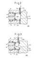
- FIG.2 A swash plate compressor 200, which is the second embodiment according to the present invention, is now shown in FIG.2.
- the modified parts relative to the swash plate compressor 100 shown in the FIG.1 is shown by an enlarged drawing and the same components as the swash plate compressor 100 are indicated with common reference numbers.
- a rear housing 213 comprises a plane portion 213c in its shaft center portion.
- the rear end surface of a coil spring 232 comes into contact with the plane portion 213c and the plane portion 213c defines a part of a spring chamber 240.
- the plane portion 213c becomes a seat portion which defines a part of the spring chamber 240 that accommodates the coil spring 232.
- the spring chamber 240 can be formed in a larger space.
- the design flexibility of the swash plate compressor 100 can be further more enlarged.
- FIG.3 A swash plate compressor 300, which is the third embodiment according to the present invention, is shown in FIG.3.
- the modified parts relative to the swash plate compressor 100 shown in the FIG.1 are shown by an enlarged drawing and the same components, as in the swash plate compressor 100, are indicated with common reference numbers.
- a rear housing 313 comprises a plane portion 313c in the shaft center portion and an annular groove 313e which surrounds the outer circumferential side of the plane portion 313c.
- the plane portion 313c and the annular groove 313e become a seat portion which defines a part of a spring chamber 340.
- the rear end of a coil spring 332 is accommodated into an annular groove 313e and the plane portion 313c present inside thereof supports the coil spring 332 from the inside.
- various types of the coil spring 332 can be disposed therein, so that the spring constant and the set load thereof can be adjusted corresponding to the specification of the swash plate compressor 300, and the design flexibility of the swash plate compressor 300 can be increased.
- each of the communication passages 213d and 313d which communicate the suction chamber 13a to the spring chambers 240 and 340, is formed as a narrow groove which is located in the front side of the rear housing 213 and 313.
- the communication passage need not to be limited to a small aperture or a narrow groove as long as it constitutes the bleed passage 30.
- the flexibility in disposing the spring chamber, in which the coil spring that biases the main shaft is accommodated can be increased and the design flexibility of the compressor can be enlarged.
- the coil spring biases the main shaft forward with a suitable load and, at the same time, for example, the shortening of the compressor length in the axial direction thereof can be facilitated.
Landscapes
- Engineering & Computer Science (AREA)
- Mechanical Engineering (AREA)
- General Engineering & Computer Science (AREA)
- Compressors, Vaccum Pumps And Other Relevant Systems (AREA)
- Compressor (AREA)
- Applications Or Details Of Rotary Compressors (AREA)
Abstract
Description
Claims (4)
- A compressor comprising:a main shaft which is input from front side with a driving force from a power source so as to rotate;a front housing, which has a shaft aperture that rotatably supports the front side of said main shaft;a cylinder block which has a shaft aperture that is located on the rear side of said front housing and rotatably supports the rear side of said main shaft, and cylinders that are disposed in parallel to said shaft aperture on the outer circumferential side of said shaft aperture;a rear housing which has a suction chamber and a discharge chamber that are disposed on the rear side of said cylinder block and can communicate with the inside of said cylinders;pistons which are reciprocatably inserted into said cylinders;a suction valve which is interposed between said cylinder block and said rear housing and only allows a gas to be drawn from said suction chamber into said cylinders;a discharge valve which is interposed between said cylinder block and said rear housing and only allows the gas to be discharged from the inside of said cylinders to said discharge chamber;a swash plate which oscillates in conjunction with the rotation of said main shaft and can reciprocate said pistons; anda coil spring which is disposed on the rear side of said main shaft and biases said main shaft from the rear side to the front side;wherein, the rear housing includes a recess or a seat portion which defines at least a part of a spring chamber that accommodates the coil spring.
- A compressor, as set forth in claim 1, wherein the spring chamber communicates with a crank chamber, which is defined by the front housing and the cylinder block, and the recess or the seat portion includes a communication passage which communicates the spring chamber to the suction chamber.
- A compressor, as set forth in claim 2, wherein the suction chamber is defined adjacent to the outer circumferential side of the recess or the seat portion.
- A compressor, as set forth in claim 1, further comprising a valve plate which is interposed between the cylinder block and the rear housing, wherein the valve plate has a hole at a center portion, through which the coil spring extends.
Applications Claiming Priority (2)
| Application Number | Priority Date | Filing Date | Title |
|---|---|---|---|
| JP2000058836A JP3937281B2 (en) | 2000-03-03 | 2000-03-03 | compressor |
| JP2000058836 | 2000-03-03 |
Publications (2)
| Publication Number | Publication Date |
|---|---|
| EP1130258A2 true EP1130258A2 (en) | 2001-09-05 |
| EP1130258A3 EP1130258A3 (en) | 2004-01-21 |
Family
ID=18579372
Family Applications (1)
| Application Number | Title | Priority Date | Filing Date |
|---|---|---|---|
| EP01104208A Withdrawn EP1130258A3 (en) | 2000-03-03 | 2001-02-22 | Compressor with a part of a spring chamber in a rear housing |
Country Status (6)
| Country | Link |
|---|---|
| US (1) | US6431841B2 (en) |
| EP (1) | EP1130258A3 (en) |
| JP (1) | JP3937281B2 (en) |
| KR (1) | KR100404950B1 (en) |
| CN (1) | CN1161541C (en) |
| BR (1) | BR0101423A (en) |
Families Citing this family (1)
| Publication number | Priority date | Publication date | Assignee | Title |
|---|---|---|---|---|
| US6751955B1 (en) * | 2003-03-20 | 2004-06-22 | Stm Power, Inc. | Stirling engine with swashplate actuator |
Family Cites Families (11)
| Publication number | Priority date | Publication date | Assignee | Title |
|---|---|---|---|---|
| US4105370A (en) * | 1977-05-19 | 1978-08-08 | General Motors Corporation | Variable displacement compressor with three-piece housing |
| JPS56106082A (en) * | 1980-01-28 | 1981-08-24 | Hitachi Ltd | Swash plate type compressor |
| US4403921A (en) * | 1980-10-27 | 1983-09-13 | Kabushiki Kaisha Toyoda Jidoshokki Seisakusho | Multi-cylinder variable delivery compressor |
| US4683803A (en) * | 1986-01-13 | 1987-08-04 | General Motors Corporation | Swash plate compressor having integral shoe and ball |
| JP3111689B2 (en) * | 1992-09-30 | 2000-11-27 | 株式会社豊田自動織機製作所 | Refrigerant gas suction mechanism in piston type compressor |
| JP3473774B2 (en) | 1993-12-21 | 2003-12-08 | 株式会社豊田自動織機 | Variable capacity compressor |
| JPH07324678A (en) * | 1994-05-31 | 1995-12-12 | Nippondenso Co Ltd | Swash plate type compressor |
| JPH09112410A (en) * | 1995-10-24 | 1997-05-02 | Mitsubishi Electric Corp | Swash plate pump |
| JPH1089246A (en) | 1996-09-18 | 1998-04-07 | Toyota Autom Loom Works Ltd | Compressor |
| JPH10281060A (en) * | 1996-12-10 | 1998-10-20 | Toyota Autom Loom Works Ltd | Variable displacement compressor |
| JPH1193833A (en) * | 1997-09-17 | 1999-04-06 | Toyota Autom Loom Works Ltd | Variable displacement swash plate type compressor |
-
2000
- 2000-03-03 JP JP2000058836A patent/JP3937281B2/en not_active Expired - Fee Related
- 2000-12-19 KR KR10-2000-0078217A patent/KR100404950B1/en not_active Expired - Fee Related
-
2001
- 2001-02-22 EP EP01104208A patent/EP1130258A3/en not_active Withdrawn
- 2001-02-22 US US09/790,919 patent/US6431841B2/en not_active Expired - Fee Related
- 2001-03-02 CN CNB011108614A patent/CN1161541C/en not_active Expired - Fee Related
- 2001-03-05 BR BR0101423-4A patent/BR0101423A/en not_active IP Right Cessation
Also Published As
| Publication number | Publication date |
|---|---|
| JP2001248551A (en) | 2001-09-14 |
| US6431841B2 (en) | 2002-08-13 |
| EP1130258A3 (en) | 2004-01-21 |
| CN1311394A (en) | 2001-09-05 |
| US20010019699A1 (en) | 2001-09-06 |
| BR0101423A (en) | 2001-11-06 |
| KR100404950B1 (en) | 2003-11-07 |
| JP3937281B2 (en) | 2007-06-27 |
| KR20010087148A (en) | 2001-09-15 |
| CN1161541C (en) | 2004-08-11 |
Similar Documents
| Publication | Publication Date | Title |
|---|---|---|
| JP7007299B2 (en) | Capacity control valve | |
| EP1612420B1 (en) | Displacement control valve for variable displacement compressor | |
| US5890876A (en) | Control valve in variable displacement compressor | |
| US6010312A (en) | Control valve unit with independently operable valve mechanisms for variable displacement compressor | |
| US5842835A (en) | Variable displacement compressor and its assembling method | |
| EP1167762B1 (en) | Lubrication system for swash plate compressor | |
| US20090246041A1 (en) | Displacement control valve of a variable displacement compressor | |
| EP0635640B1 (en) | Bearing structure used in a compressor | |
| US8439652B2 (en) | Suction throttle valve for variable displacement type compressor | |
| JP2002031050A (en) | Compressor | |
| US6146107A (en) | Variable displacement compressor | |
| EP1001171A2 (en) | Variable displacement compressor | |
| US6350106B1 (en) | Variable displacement compressor with capacity control mechanism | |
| US6544004B2 (en) | Single-headed piston type compressor | |
| EP1936191A2 (en) | Variable displacement compressor | |
| JP2003035274A (en) | Control valve for variable displacement compressor | |
| US6431841B2 (en) | Compressor with a part of a spring chamber in a rear housing | |
| US10815980B2 (en) | Variable displacement swash plate type compressor | |
| EP1070845A1 (en) | Crank pressure control mechanism of variable displacement compressor | |
| EP1548281A2 (en) | Piston type compressor | |
| US6532860B2 (en) | Piston type compressor and inner mold for making the same | |
| US20160252084A1 (en) | Variable displacement swash plate type compressor | |
| KR20190091835A (en) | Electronic control valve and compressor with the same | |
| US20010043866A1 (en) | Electric compressor | |
| JP4684166B2 (en) | Swash plate type variable displacement compressor |
Legal Events
| Date | Code | Title | Description |
|---|---|---|---|
| PUAI | Public reference made under article 153(3) epc to a published international application that has entered the european phase |
Free format text: ORIGINAL CODE: 0009012 |
|
| 17P | Request for examination filed |
Effective date: 20010222 |
|
| AK | Designated contracting states |
Kind code of ref document: A2 Designated state(s): AT BE CH CY DE DK ES FI FR GB GR IE IT LI LU MC NL PT SE TR |
|
| AX | Request for extension of the european patent |
Free format text: AL;LT;LV;MK;RO;SI |
|
| RAP1 | Party data changed (applicant data changed or rights of an application transferred) |
Owner name: KABUSHIKI KAISHA TOYOTA JIDOSHOKKI |
|
| PUAL | Search report despatched |
Free format text: ORIGINAL CODE: 0009013 |
|
| AK | Designated contracting states |
Kind code of ref document: A3 Designated state(s): AT BE CH CY DE DK ES FI FR GB GR IE IT LI LU MC NL PT SE TR |
|
| AX | Request for extension of the european patent |
Extension state: AL LT LV MK RO SI |
|
| AKX | Designation fees paid |
Designated state(s): DE FR IT |
|
| STAA | Information on the status of an ep patent application or granted ep patent |
Free format text: STATUS: THE APPLICATION HAS BEEN WITHDRAWN |
|
| 18W | Application withdrawn |
Effective date: 20050310 |