EP1130252A2 - Starter device for starting automobile use engine - Google Patents
Starter device for starting automobile use engine Download PDFInfo
- Publication number
- EP1130252A2 EP1130252A2 EP01102801A EP01102801A EP1130252A2 EP 1130252 A2 EP1130252 A2 EP 1130252A2 EP 01102801 A EP01102801 A EP 01102801A EP 01102801 A EP01102801 A EP 01102801A EP 1130252 A2 EP1130252 A2 EP 1130252A2
- Authority
- EP
- European Patent Office
- Prior art keywords
- anchoring
- starter device
- manipulation
- automobile use
- bracket
- Prior art date
- Legal status (The legal status is an assumption and is not a legal conclusion. Google has not performed a legal analysis and makes no representation as to the accuracy of the status listed.)
- Granted
Links
Images

Classifications
-
- F—MECHANICAL ENGINEERING; LIGHTING; HEATING; WEAPONS; BLASTING
- F02—COMBUSTION ENGINES; HOT-GAS OR COMBUSTION-PRODUCT ENGINE PLANTS
- F02N—STARTING OF COMBUSTION ENGINES; STARTING AIDS FOR SUCH ENGINES, NOT OTHERWISE PROVIDED FOR
- F02N15/00—Other power-operated starting apparatus; Component parts, details, or accessories, not provided for in, or of interest apart from groups F02N5/00 - F02N13/00
- F02N15/006—Assembling or mounting of starting devices
-
- F—MECHANICAL ENGINEERING; LIGHTING; HEATING; WEAPONS; BLASTING
- F02—COMBUSTION ENGINES; HOT-GAS OR COMBUSTION-PRODUCT ENGINE PLANTS
- F02N—STARTING OF COMBUSTION ENGINES; STARTING AIDS FOR SUCH ENGINES, NOT OTHERWISE PROVIDED FOR
- F02N15/00—Other power-operated starting apparatus; Component parts, details, or accessories, not provided for in, or of interest apart from groups F02N5/00 - F02N13/00
-
- F—MECHANICAL ENGINEERING; LIGHTING; HEATING; WEAPONS; BLASTING
- F16—ENGINEERING ELEMENTS AND UNITS; GENERAL MEASURES FOR PRODUCING AND MAINTAINING EFFECTIVE FUNCTIONING OF MACHINES OR INSTALLATIONS; THERMAL INSULATION IN GENERAL
- F16C—SHAFTS; FLEXIBLE SHAFTS; ELEMENTS OR CRANKSHAFT MECHANISMS; ROTARY BODIES OTHER THAN GEARING ELEMENTS; BEARINGS
- F16C1/00—Flexible shafts; Mechanical means for transmitting movement in a flexible sheathing
- F16C1/10—Means for transmitting linear movement in a flexible sheathing, e.g. "Bowden-mechanisms"
- F16C1/102—Arrangements to mount end fittings of the sheathings to support walls or brackets
- F16C1/105—Arrangements to mount end fittings of the sheathings to support walls or brackets to a slot in the bracket
-
- F—MECHANICAL ENGINEERING; LIGHTING; HEATING; WEAPONS; BLASTING
- F16—ENGINEERING ELEMENTS AND UNITS; GENERAL MEASURES FOR PRODUCING AND MAINTAINING EFFECTIVE FUNCTIONING OF MACHINES OR INSTALLATIONS; THERMAL INSULATION IN GENERAL
- F16C—SHAFTS; FLEXIBLE SHAFTS; ELEMENTS OR CRANKSHAFT MECHANISMS; ROTARY BODIES OTHER THAN GEARING ELEMENTS; BEARINGS
- F16C1/00—Flexible shafts; Mechanical means for transmitting movement in a flexible sheathing
- F16C1/26—Construction of guiding-sheathings or guiding-tubes
- F16C1/262—End fittings; Attachment thereof to the sheathing or tube
-
- F—MECHANICAL ENGINEERING; LIGHTING; HEATING; WEAPONS; BLASTING
- F16—ENGINEERING ELEMENTS AND UNITS; GENERAL MEASURES FOR PRODUCING AND MAINTAINING EFFECTIVE FUNCTIONING OF MACHINES OR INSTALLATIONS; THERMAL INSULATION IN GENERAL
- F16H—GEARING
- F16H61/00—Control functions within control units of change-speed- or reversing-gearings for conveying rotary motion ; Control of exclusively fluid gearing, friction gearing, gearings with endless flexible members or other particular types of gearing
- F16H61/26—Generation or transmission of movements for final actuating mechanisms
- F16H61/36—Generation or transmission of movements for final actuating mechanisms with at least one movement being transmitted by a cable
-
- F—MECHANICAL ENGINEERING; LIGHTING; HEATING; WEAPONS; BLASTING
- F16—ENGINEERING ELEMENTS AND UNITS; GENERAL MEASURES FOR PRODUCING AND MAINTAINING EFFECTIVE FUNCTIONING OF MACHINES OR INSTALLATIONS; THERMAL INSULATION IN GENERAL
- F16C—SHAFTS; FLEXIBLE SHAFTS; ELEMENTS OR CRANKSHAFT MECHANISMS; ROTARY BODIES OTHER THAN GEARING ELEMENTS; BEARINGS
- F16C2326/00—Articles relating to transporting
- F16C2326/01—Parts of vehicles in general
-
- F—MECHANICAL ENGINEERING; LIGHTING; HEATING; WEAPONS; BLASTING
- F16—ENGINEERING ELEMENTS AND UNITS; GENERAL MEASURES FOR PRODUCING AND MAINTAINING EFFECTIVE FUNCTIONING OF MACHINES OR INSTALLATIONS; THERMAL INSULATION IN GENERAL
- F16C—SHAFTS; FLEXIBLE SHAFTS; ELEMENTS OR CRANKSHAFT MECHANISMS; ROTARY BODIES OTHER THAN GEARING ELEMENTS; BEARINGS
- F16C2326/00—Articles relating to transporting
- F16C2326/20—Land vehicles
-
- F—MECHANICAL ENGINEERING; LIGHTING; HEATING; WEAPONS; BLASTING
- F16—ENGINEERING ELEMENTS AND UNITS; GENERAL MEASURES FOR PRODUCING AND MAINTAINING EFFECTIVE FUNCTIONING OF MACHINES OR INSTALLATIONS; THERMAL INSULATION IN GENERAL
- F16C—SHAFTS; FLEXIBLE SHAFTS; ELEMENTS OR CRANKSHAFT MECHANISMS; ROTARY BODIES OTHER THAN GEARING ELEMENTS; BEARINGS
- F16C2361/00—Apparatus or articles in engineering in general
- F16C2361/65—Gear shifting, change speed gear, gear box
-
- Y—GENERAL TAGGING OF NEW TECHNOLOGICAL DEVELOPMENTS; GENERAL TAGGING OF CROSS-SECTIONAL TECHNOLOGIES SPANNING OVER SEVERAL SECTIONS OF THE IPC; TECHNICAL SUBJECTS COVERED BY FORMER USPC CROSS-REFERENCE ART COLLECTIONS [XRACs] AND DIGESTS
- Y10—TECHNICAL SUBJECTS COVERED BY FORMER USPC
- Y10T—TECHNICAL SUBJECTS COVERED BY FORMER US CLASSIFICATION
- Y10T74/00—Machine element or mechanism
- Y10T74/13—Machine starters
-
- Y—GENERAL TAGGING OF NEW TECHNOLOGICAL DEVELOPMENTS; GENERAL TAGGING OF CROSS-SECTIONAL TECHNOLOGIES SPANNING OVER SEVERAL SECTIONS OF THE IPC; TECHNICAL SUBJECTS COVERED BY FORMER USPC CROSS-REFERENCE ART COLLECTIONS [XRACs] AND DIGESTS
- Y10—TECHNICAL SUBJECTS COVERED BY FORMER USPC
- Y10T—TECHNICAL SUBJECTS COVERED BY FORMER US CLASSIFICATION
- Y10T74/00—Machine element or mechanism
- Y10T74/20—Control lever and linkage systems
- Y10T74/20012—Multiple controlled elements
- Y10T74/20018—Transmission control
- Y10T74/20049—Transmission controlled by flexible cable
-
- Y—GENERAL TAGGING OF NEW TECHNOLOGICAL DEVELOPMENTS; GENERAL TAGGING OF CROSS-SECTIONAL TECHNOLOGIES SPANNING OVER SEVERAL SECTIONS OF THE IPC; TECHNICAL SUBJECTS COVERED BY FORMER USPC CROSS-REFERENCE ART COLLECTIONS [XRACs] AND DIGESTS
- Y10—TECHNICAL SUBJECTS COVERED BY FORMER USPC
- Y10T—TECHNICAL SUBJECTS COVERED BY FORMER US CLASSIFICATION
- Y10T74/00—Machine element or mechanism
- Y10T74/20—Control lever and linkage systems
- Y10T74/20396—Hand operated
- Y10T74/20402—Flexible transmitter [e.g., Bowden cable]
- Y10T74/2045—Flexible transmitter [e.g., Bowden cable] and sheath support, connector, or anchor
Definitions
- the present invention relates to a starter device for starting an automobile use engine and, in particular, relates to a starter device for starting an automobile use engine which includes an anchoring bracket for intermediately anchoring a manipulation cable coupling between a manipulation side and an actuation side of an automobile transmission mechanism and being formed integral with the starter device.
- a vehicle speed change gear at an actuation side in the transmission mechanism is generally shifted through a manual or automatic manipulation effort at a manipulation side thereof, therefore, the manipulation side and the actuation side thereof are coupled via a mechanical manipulation cable.
- the manipulation cable is generally anchored at its midway through provision of a dedicated anchoring use bracket formed such as on an engine block and a transmission mechanism so as to limit a neck oscillation movement of a core wire (inner wire) of the manipulation cable.
- An object of the present invention is to improve the positional accuracy for the intermediate anchoring point of the manipulation cable with respect to the manipulation point, the actuation point, the engine and the transmission mechanism block and, in particular, with respect to the actuation point and to achieve an accurate vehicle speed change gear shifting.
- Another object of the present invention is to provide a starter device for starting an automobile use engine which achieves the above object with a very reasonable and easy means.
- the present invention is to provide a starter device for starting an automobile engine which includes an anchoring bracket for intermediately anchoring the manipulation cable formed integrally therewith.
- the present invention preferably provides a starter device for starting an automobile use engine, characterized in that the anchoring bracket is integrally provided with a starter front bracket which is designed to attach the starter device to the engine block.
- the present invention preferably provides a starter device for starting an automobile use engine, characterized in that the anchoring bracket and the starter front bracket are formed integrally by molding through aluminum casting.
- the starter front bracket and the anchoring bracket for intermediately securing the manipulation cable are formed integrally.
- JP-A-5-44523 (1993) does not relate to the intermediate anchoring for the manipulation cable as in the present invention and suggests no specific means therefor.
- a starter 2 which is designed to start an automobile engine is provided with a pinion 23 which is rotated by a motor not illustrated, and when the pinion 23 is displaced upward direction in Fig. 1 and is engaged with a ring gear 32, the engine is started. Therefore, a front bracket 21 in the starter 2 is attached and secured to a transmission mechanism block 1 by bolts 5 through such as spigot fit, knock pin fit and face match fit in order to position with a good accuracy with respect to such as the ring gear 32 and an engine block 3.
- the ring gear 32 is directly connected to a crank shaft 31 of the engine not illustrated and further the engine block 3 is assembled with the transmission mechanism block 1 so as to be properly positioned with respect to a vehicle speed change gear (not illustrated) in the transmission mechanism block 1.
- a mechanical manipulation cable 4 is for connecting an actuation point 1a of a cam mechanism 11 for shifting the vehicle speed change gear with an manipulation point (not illustrated) of the transmission mechanism which is manipulated manually or automatically, and an intermediate sheath portion 42 of the manipulation cable 4 is intermediately anchored to an anchoring bracket 22 by means of a clip 43.
- the purposes of the intermediate anchoring of the manipulation cable 4 are such as for preventing the manipulation cable 4 from interfering with an obstacle at the midway thereof, for smoothing the sliding movement of the core wire 41 and for limiting a range of neck swing of the core wire 41.
- the anchoring bracket 22 is molded integral with the front bracket 21 of the starter 2 through aluminum casting. Therefore, the intermediate anchoring sheath portion 42 of the manipulation cable 4 which is attached to the anchoring bracket 22 is positioned and assembled with a high positional accuracy with respect to such as the cam mechanism 11, the actuation point la thereof and the transmission mechanism block 1 accommodating the vehicle speed change gear.
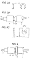
- Fig. 2 is a perspective view around the anchoring bracket 22 integrally formed with the starter front bracket 21 and Figs. 3A ⁇ 3C and 4 are views for explaining a method of intermediate anchoring of the manipulation cable 4.
- the anchoring bracket 22 is molded integrally with the aluminum made front bracket 21 as has been explained above, and the anchoring bracket 21 is provided with a cut-out guide portion 22a which permits to pass a part of intermediate anchoring sheath portion 42 having the smallest diameter ⁇ A of the manipulation cable 4 and a round window 22b into which another part of the intermediate anchoring sheath portion 42 having the second smallest diameter ⁇ B is to be set.
- the part of intermediate anchoring sheath portion 42 having the smallest diameter ⁇ A of the manipulation cable 4 is passed through the guide portion 22a, then the part thereof having the second smallest diameter ⁇ B is set into the round window 22b, thereafter, the clip 43 fitted into the part thereof having the smallest diameter ⁇ A, thus, the intermediate anchoring sheath portion 42 of the manipulation cable 4 is intermediately anchored at the anchoring bracket 22 and resultantly at the front bracket 21 of the starter 2 with a good positional accuracy.
- the anchoring bracket 22 is molded integral with the front bracket 21 of the starter 2 through aluminum casing, however, the present invention is not necessarily limited to such embodiment, and further with regard to the specific intermediate anchoring means there are of course a variety of modifications.
- the manipulation cable can be intermediately anchored with a high positional accuracy through a small number of parts and a comparatively simple means.
- the intermediate anchoring means for the manipulation cable is provided integral with the starter device, the intermediate anchoring point of the manipulating cable with respect to the actuation point of shifting the vehicle speed change gear can be positioned with a high positional accuracy by merely attaching the starter device at its predetermined position, thereby, through the improvement of the positional accuracy an advantage that an accurate vehicle speed change gear shifting can be performed is obtained.
Landscapes
- Engineering & Computer Science (AREA)
- General Engineering & Computer Science (AREA)
- Mechanical Engineering (AREA)
- Health & Medical Sciences (AREA)
- Oral & Maxillofacial Surgery (AREA)
- Chemical & Material Sciences (AREA)
- Combustion & Propulsion (AREA)
- Gear-Shifting Mechanisms (AREA)
- Flexible Shafts (AREA)
Abstract
Description
Claims (5)
- In a combination including an automobile use engine having a transmission mechanism coupling between a manipulation side and an actuation side via a manipulation cable 4 for shifting a vehicle speed change gear and a starter device 2 for starting the automobile use engine for rotating a ring gear 32 coupled to a crank shaft 31 of the automobile use engine to start the same, the starter device for starting the automobile use engine comprising, a anchoring bracket 22 which intermediately anchors the manipulation cable 4 is formed integrally with the starter device for starting the automobile use engine.
- A starter device for starting an automobile use engine according to claim 1, wherein the anchoring bracket 22 is formed integral with a front bracket 21 of the starter device 2 for anchoring the same to an engine block.
- A starter device for starting an automobile use engine according to claim 2, wherein the anchoring bracket 22 and the front bracket 21 are molded integral through aluminum casting.
- A starter device for starting an automobile use engine according to claim 1, wherein the manipulation cable 4 is intermediately anchored to the anchoring bracket 22 via a sheath portion 42 of the manipulation cable.
- A starter device for starting an automobile use engine according to claim 4, wherein the sheath portion 42 includes a first portion having the smallest diameter A which is permitted to pass a cut-out guide portion 22a formed at the anchoring bracket 22 and a second portion having the second smallest diameter B which is designed to set at a round window 22b formed at the anchoring bracket 22.
Applications Claiming Priority (2)
| Application Number | Priority Date | Filing Date | Title |
|---|---|---|---|
| JP2000061893 | 2000-03-02 | ||
| JP2000061893A JP3488167B2 (en) | 2000-03-02 | 2000-03-02 | Starter device for automobile engine start |
Publications (3)
| Publication Number | Publication Date |
|---|---|
| EP1130252A2 true EP1130252A2 (en) | 2001-09-05 |
| EP1130252A3 EP1130252A3 (en) | 2003-04-09 |
| EP1130252B1 EP1130252B1 (en) | 2004-07-28 |
Family
ID=18581971
Family Applications (1)
| Application Number | Title | Priority Date | Filing Date |
|---|---|---|---|
| EP01102801A Expired - Lifetime EP1130252B1 (en) | 2000-03-02 | 2001-02-09 | Starter device for starting automobile use engine |
Country Status (4)
| Country | Link |
|---|---|
| US (1) | US6460428B2 (en) |
| EP (1) | EP1130252B1 (en) |
| JP (1) | JP3488167B2 (en) |
| DE (1) | DE60104459T2 (en) |
Families Citing this family (2)
| Publication number | Priority date | Publication date | Assignee | Title |
|---|---|---|---|---|
| JP5781360B2 (en) * | 2011-04-21 | 2015-09-24 | 株式会社ユーシン | Control cable terminal fixing device |
| JP5849446B2 (en) * | 2011-06-13 | 2016-01-27 | 株式会社デンソー | Starter |
Family Cites Families (19)
| Publication number | Priority date | Publication date | Assignee | Title |
|---|---|---|---|---|
| US4782686A (en) * | 1987-06-01 | 1988-11-08 | Carson Jr Edward C | Tube bender for greenhouse structural supports |
| KR930002427B1 (en) * | 1988-10-26 | 1993-03-30 | 마쯔다 가부시기가이샤 | Throttle cable coloration method of automatic transmission and its mounting structure |
| US5048478A (en) * | 1989-07-13 | 1991-09-17 | Tecumseh Products Company | Single cylinder engine having multi-functional bracket and method of assembling same |
| US5163335A (en) * | 1991-07-15 | 1992-11-17 | Patrick D. Isom | Universal starter motor assembly |
| JP3015157B2 (en) * | 1991-08-14 | 2000-03-06 | 株式会社日立製作所 | Starter with built-in rotation sensor |
| JP2874481B2 (en) * | 1992-09-30 | 1999-03-24 | スズキ株式会社 | Power assist device for vehicle clutch |
| US5662004A (en) * | 1995-01-19 | 1997-09-02 | Grand Haven Stamped Products, Div. Of Jsj Corporation | Vehicle shift cable connection |
| JPH0914434A (en) * | 1995-06-28 | 1997-01-14 | Chuo Spring Co Ltd | Transmission control device for automobile |
| US5603297A (en) * | 1996-01-18 | 1997-02-18 | Acoust-A-Fiber Research And Development, Inc. | Heat Shield |
| JP3290353B2 (en) * | 1996-07-01 | 2002-06-10 | 三菱電機株式会社 | Engine starter |
| JP3241282B2 (en) * | 1996-12-06 | 2001-12-25 | 株式会社日立製作所 | Automotive starter motor and automotive starter |
| GB9714060D0 (en) * | 1997-07-03 | 1997-09-10 | Adwest Bowden Tsk Limited | Means for anchoring an elongate member |
| US5967252A (en) * | 1997-09-29 | 1999-10-19 | Uri Rapoport | Push button actuation system for ATV transmission |
| DE19801343A1 (en) * | 1998-01-16 | 1999-07-22 | United Parts Fhs Automobil Sys | Quick-release fastening for actuating cable in vehicle with axial tolerance compensation |
| US6092436A (en) * | 1998-07-28 | 2000-07-25 | General Motors Corporation | Anchorage for motion-transmitting cable assembly |
| US6327928B1 (en) * | 1998-10-23 | 2001-12-11 | Brian C. Bowerman | Steering column shifter assembly |
| JP4368019B2 (en) * | 1998-12-22 | 2009-11-18 | 中央発條株式会社 | Cable terminal fixing device |
| GB2346186B (en) * | 1999-01-26 | 2002-11-27 | Adwest Bowden Tsk Ltd | Means for anchoring an elongate member |
| DE10006690C1 (en) * | 2000-02-15 | 2001-06-28 | Ktm Sportmotorcycle Ag Mattigh | Starter for motorcycle two-cylinder V-configuration internal combustion engine has starter motor and gearbox mounted in V-shaped intermediate space between cylinders above crankshaft |
-
2000
- 2000-03-02 JP JP2000061893A patent/JP3488167B2/en not_active Expired - Fee Related
-
2001
- 2001-02-09 EP EP01102801A patent/EP1130252B1/en not_active Expired - Lifetime
- 2001-02-09 DE DE60104459T patent/DE60104459T2/en not_active Expired - Lifetime
- 2001-03-02 US US09/796,535 patent/US6460428B2/en not_active Expired - Lifetime
Also Published As
| Publication number | Publication date |
|---|---|
| EP1130252B1 (en) | 2004-07-28 |
| DE60104459D1 (en) | 2004-09-02 |
| JP3488167B2 (en) | 2004-01-19 |
| DE60104459T2 (en) | 2005-08-04 |
| JP2001248528A (en) | 2001-09-14 |
| US20010019983A1 (en) | 2001-09-06 |
| US6460428B2 (en) | 2002-10-08 |
| EP1130252A3 (en) | 2003-04-09 |
Similar Documents
| Publication | Publication Date | Title |
|---|---|---|
| EP0177259B1 (en) | Engine starter with a planetary reduction gear | |
| EP0828067A2 (en) | A throttle valve control device for an internal combustion engine | |
| US6134977A (en) | Starter for internal combustion engines | |
| US6460428B2 (en) | Starter device for starting automobile use engine | |
| JPH0420820B2 (en) | ||
| WO2005108197A1 (en) | Accelerator operating device | |
| JPH0419667U (en) | ||
| JP3011091B2 (en) | Starter | |
| US5265485A (en) | Starting motor with an intermediate gear | |
| KR100385688B1 (en) | A device for controlling intake air quantity of combustion engine and a method of producing the same | |
| US6813967B2 (en) | Starter with driving lever having lever pin | |
| US6035732A (en) | Starter having a ventilation passage | |
| JP2001116127A (en) | Terminal body mounting method and terminal body | |
| CN218228656U (en) | Accelerator opening degree control device | |
| JP2588059Y2 (en) | Engine stop actuator | |
| US4715738A (en) | Carburetor throttle lever/speed control connector | |
| JP2597794Y2 (en) | Actuator | |
| KR200221001Y1 (en) | Stopper for starting motor | |
| JPH02230956A (en) | Starting motor | |
| JPH0225886Y2 (en) | ||
| JPS6213865Y2 (en) | ||
| JPH10153041A (en) | Cable drive device such as window regulator | |
| KR100677714B1 (en) | Overrunning Clutch Lever for Start Motor | |
| JP2009180152A (en) | Starter | |
| JPS58119446U (en) | Rotating car windshield wiper |
Legal Events
| Date | Code | Title | Description |
|---|---|---|---|
| PUAI | Public reference made under article 153(3) epc to a published international application that has entered the european phase |
Free format text: ORIGINAL CODE: 0009012 |
|
| AK | Designated contracting states |
Kind code of ref document: A2 Designated state(s): AT BE CH CY DE DK ES FI FR GB GR IE IT LI LU MC NL PT SE TR |
|
| AX | Request for extension of the european patent |
Free format text: AL;LT;LV;MK;RO;SI |
|
| PUAL | Search report despatched |
Free format text: ORIGINAL CODE: 0009013 |
|
| AK | Designated contracting states |
Kind code of ref document: A3 Designated state(s): AT BE CH CY DE DK ES FI FR GB GR IE IT LI LU MC NL PT SE TR |
|
| AX | Request for extension of the european patent |
Extension state: AL LT LV MK RO SI |
|
| 17P | Request for examination filed |
Effective date: 20030806 |
|
| 17Q | First examination report despatched |
Effective date: 20030905 |
|
| AKX | Designation fees paid |
Designated state(s): DE FR IT |
|
| GRAP | Despatch of communication of intention to grant a patent |
Free format text: ORIGINAL CODE: EPIDOSNIGR1 |
|
| GRAS | Grant fee paid |
Free format text: ORIGINAL CODE: EPIDOSNIGR3 |
|
| GRAA | (expected) grant |
Free format text: ORIGINAL CODE: 0009210 |
|
| AK | Designated contracting states |
Kind code of ref document: B1 Designated state(s): DE FR IT |
|
| REG | Reference to a national code |
Ref country code: IE Ref legal event code: FG4D |
|
| REF | Corresponds to: |
Ref document number: 60104459 Country of ref document: DE Date of ref document: 20040902 Kind code of ref document: P |
|
| ET | Fr: translation filed | ||
| PLBE | No opposition filed within time limit |
Free format text: ORIGINAL CODE: 0009261 |
|
| STAA | Information on the status of an ep patent application or granted ep patent |
Free format text: STATUS: NO OPPOSITION FILED WITHIN TIME LIMIT |
|
| 26N | No opposition filed |
Effective date: 20050429 |
|
| REG | Reference to a national code |
Ref country code: FR Ref legal event code: PLFP Year of fee payment: 15 |
|
| PGFP | Annual fee paid to national office [announced via postgrant information from national office to epo] |
Ref country code: DE Payment date: 20150203 Year of fee payment: 15 Ref country code: IT Payment date: 20150218 Year of fee payment: 15 |
|
| PGFP | Annual fee paid to national office [announced via postgrant information from national office to epo] |
Ref country code: FR Payment date: 20150210 Year of fee payment: 15 |
|
| REG | Reference to a national code |
Ref country code: DE Ref legal event code: R119 Ref document number: 60104459 Country of ref document: DE |
|
| REG | Reference to a national code |
Ref country code: FR Ref legal event code: ST Effective date: 20161028 |
|
| PG25 | Lapsed in a contracting state [announced via postgrant information from national office to epo] |
Ref country code: IT Free format text: LAPSE BECAUSE OF NON-PAYMENT OF DUE FEES Effective date: 20160209 |
|
| PG25 | Lapsed in a contracting state [announced via postgrant information from national office to epo] |
Ref country code: FR Free format text: LAPSE BECAUSE OF NON-PAYMENT OF DUE FEES Effective date: 20160229 Ref country code: DE Free format text: LAPSE BECAUSE OF NON-PAYMENT OF DUE FEES Effective date: 20160901 |