EP1130072A1 - Chemically adsorbable substance for thin film formation and process for producing the same - Google Patents
Chemically adsorbable substance for thin film formation and process for producing the same Download PDFInfo
- Publication number
- EP1130072A1 EP1130072A1 EP00944298A EP00944298A EP1130072A1 EP 1130072 A1 EP1130072 A1 EP 1130072A1 EP 00944298 A EP00944298 A EP 00944298A EP 00944298 A EP00944298 A EP 00944298A EP 1130072 A1 EP1130072 A1 EP 1130072A1
- Authority
- EP
- European Patent Office
- Prior art keywords
- liquid crystal
- adsorption
- molecules
- alignment film
- substrate
- Prior art date
- Legal status (The legal status is an assumption and is not a legal conclusion. Google has not performed a legal analysis and makes no representation as to the accuracy of the status listed.)
- Withdrawn
Links
- 0 C*Oc1ccc(C=CC(c(cc2)ccc2O*(C)O)=O)cc1 Chemical compound C*Oc1ccc(C=CC(c(cc2)ccc2O*(C)O)=O)cc1 0.000 description 1
- XNTDVLHRNIIJAP-QXMHVHEDSA-N C/C(/c(cc1)ccc1OC)=C/C(c(cc1)ccc1O)=O Chemical compound C/C(/c(cc1)ccc1OC)=C/C(c(cc1)ccc1O)=O XNTDVLHRNIIJAP-QXMHVHEDSA-N 0.000 description 1
Images



Classifications
-
- C—CHEMISTRY; METALLURGY
- C07—ORGANIC CHEMISTRY
- C07F—ACYCLIC, CARBOCYCLIC OR HETEROCYCLIC COMPOUNDS CONTAINING ELEMENTS OTHER THAN CARBON, HYDROGEN, HALOGEN, OXYGEN, NITROGEN, SULFUR, SELENIUM OR TELLURIUM
- C07F7/00—Compounds containing elements of Groups 4 or 14 of the Periodic Table
- C07F7/02—Silicon compounds
- C07F7/08—Compounds having one or more C—Si linkages
- C07F7/12—Organo silicon halides
-
- B—PERFORMING OPERATIONS; TRANSPORTING
- B01—PHYSICAL OR CHEMICAL PROCESSES OR APPARATUS IN GENERAL
- B01J—CHEMICAL OR PHYSICAL PROCESSES, e.g. CATALYSIS OR COLLOID CHEMISTRY; THEIR RELEVANT APPARATUS
- B01J19/00—Chemical, physical or physico-chemical processes in general; Their relevant apparatus
-
- B—PERFORMING OPERATIONS; TRANSPORTING
- B82—NANOTECHNOLOGY
- B82Y—SPECIFIC USES OR APPLICATIONS OF NANOSTRUCTURES; MEASUREMENT OR ANALYSIS OF NANOSTRUCTURES; MANUFACTURE OR TREATMENT OF NANOSTRUCTURES
- B82Y30/00—Nanotechnology for materials or surface science, e.g. nanocomposites
-
- C—CHEMISTRY; METALLURGY
- C07—ORGANIC CHEMISTRY
- C07F—ACYCLIC, CARBOCYCLIC OR HETEROCYCLIC COMPOUNDS CONTAINING ELEMENTS OTHER THAN CARBON, HYDROGEN, HALOGEN, OXYGEN, NITROGEN, SULFUR, SELENIUM OR TELLURIUM
- C07F7/00—Compounds containing elements of Groups 4 or 14 of the Periodic Table
- C07F7/02—Silicon compounds
- C07F7/025—Silicon compounds without C-silicon linkages
-
- C—CHEMISTRY; METALLURGY
- C09—DYES; PAINTS; POLISHES; NATURAL RESINS; ADHESIVES; COMPOSITIONS NOT OTHERWISE PROVIDED FOR; APPLICATIONS OF MATERIALS NOT OTHERWISE PROVIDED FOR
- C09K—MATERIALS FOR MISCELLANEOUS APPLICATIONS, NOT PROVIDED FOR ELSEWHERE
- C09K3/00—Materials not provided for elsewhere
-
- G—PHYSICS
- G02—OPTICS
- G02F—OPTICAL DEVICES OR ARRANGEMENTS FOR THE CONTROL OF LIGHT BY MODIFICATION OF THE OPTICAL PROPERTIES OF THE MEDIA OF THE ELEMENTS INVOLVED THEREIN; NON-LINEAR OPTICS; FREQUENCY-CHANGING OF LIGHT; OPTICAL LOGIC ELEMENTS; OPTICAL ANALOGUE/DIGITAL CONVERTERS
- G02F1/00—Devices or arrangements for the control of the intensity, colour, phase, polarisation or direction of light arriving from an independent light source, e.g. switching, gating or modulating; Non-linear optics
- G02F1/01—Devices or arrangements for the control of the intensity, colour, phase, polarisation or direction of light arriving from an independent light source, e.g. switching, gating or modulating; Non-linear optics for the control of the intensity, phase, polarisation or colour
- G02F1/13—Devices or arrangements for the control of the intensity, colour, phase, polarisation or direction of light arriving from an independent light source, e.g. switching, gating or modulating; Non-linear optics for the control of the intensity, phase, polarisation or colour based on liquid crystals, e.g. single liquid crystal display cells
- G02F1/133—Constructional arrangements; Operation of liquid crystal cells; Circuit arrangements
- G02F1/1333—Constructional arrangements; Manufacturing methods
- G02F1/1337—Surface-induced orientation of the liquid crystal molecules, e.g. by alignment layers
-
- Y—GENERAL TAGGING OF NEW TECHNOLOGICAL DEVELOPMENTS; GENERAL TAGGING OF CROSS-SECTIONAL TECHNOLOGIES SPANNING OVER SEVERAL SECTIONS OF THE IPC; TECHNICAL SUBJECTS COVERED BY FORMER USPC CROSS-REFERENCE ART COLLECTIONS [XRACs] AND DIGESTS
- Y10—TECHNICAL SUBJECTS COVERED BY FORMER USPC
- Y10T—TECHNICAL SUBJECTS COVERED BY FORMER US CLASSIFICATION
- Y10T428/00—Stock material or miscellaneous articles
- Y10T428/31504—Composite [nonstructural laminate]
- Y10T428/3154—Of fluorinated addition polymer from unsaturated monomers
-
- Y—GENERAL TAGGING OF NEW TECHNOLOGICAL DEVELOPMENTS; GENERAL TAGGING OF CROSS-SECTIONAL TECHNOLOGIES SPANNING OVER SEVERAL SECTIONS OF THE IPC; TECHNICAL SUBJECTS COVERED BY FORMER USPC CROSS-REFERENCE ART COLLECTIONS [XRACs] AND DIGESTS
- Y10—TECHNICAL SUBJECTS COVERED BY FORMER USPC
- Y10T—TECHNICAL SUBJECTS COVERED BY FORMER US CLASSIFICATION
- Y10T428/00—Stock material or miscellaneous articles
- Y10T428/31504—Composite [nonstructural laminate]
- Y10T428/31652—Of asbestos
- Y10T428/31663—As siloxane, silicone or silane
Definitions
- the present invention relates to a chemical adsorption material to be chemically adsorbed on a surface of a substrate to form a thin film thereon and to a producing method thereof. More particularly, the present invention relates to a chemical adsorption material used mainly as liquid crystal alignment film coating material for forming a thin film and to a producing method thereof. Also, the present invention relates to an organic thin film formed by use of the thin film forming chemical adsorption material and to a producing method thereof. Further, the present invention relates to a liquid crystal alignment film and to a producing method thereof.
- the present invention relates to a liquid crystal display using the same and to a producing method thereof and, further particularly, to a liquid crystal alignment film for use in a plane display panel using liquid crystals to display television (TV) picture, computer picture and the like, to a producing method thereof, and to a liquid crystal display device using it.
- TV television
- the present invention relates to a liquid crystal display using the same and to a producing method thereof and, further particularly, to a liquid crystal alignment film for use in a plane display panel using liquid crystals to display television (TV) picture, computer picture and the like, to a producing method thereof, and to a liquid crystal display device using it.
- TV television
- liquid crystal elements come into wide use rapidly as means for miniaturization of information technology equipment.
- a liquid crystal alignment film which is the critical component of the liquid crystal elements is subjected to a rubbing process which can be cited as a typical alignment film treatment process.
- the rubbing process has difficulties of deterioration of display quality caused by generation of fine dusts and rubbing lines and others.
- rubbingless alignment film treatments such as an optical alignment film treatment, are now under study.
- optical alignment film treatments include the process that an alignment film made of polymer, such as polyimide or polyvinyl alcohol, is irradiated with polarized ultraviolet light for alignment film treatment.
- Another approach was also reported (by Japanese Patent Application No. Hei 8-224,219), in which the optical alignment film treatment is given to the optical alignment film comprising chemical adsorption monomolecular film, as well as to that of polymer such as polyimide.
- the optical alignment film treatment is performed under the alignment mechanism that admolecules of the film are irradiated with polarized light so as to be re-aligned, so that the liquid crystal molecules are aligned along the polarization direction.
- the alignment film comprising polymer
- it has the molecular structure that polymers are complicated densely and irregularly, except its surface part. Because of this, only a part of a surface of the film from which tip portions of the polymer projects out can contribute to the alignment of the liquid crystal molecules. In addition to this, because of uncertainty of the alignment orientation of the side chain, the functional group contributive to the alignment is not always exposed on the surface. Consequently, the part thereof contributive to the alignment of the liquid crystal molecules is obviously smaller in density than that of the monomolecular film, thus suffering the disadvantage that it is difficult to make an adequate control of alignment of the liquid crystals. Also, since the alignment film comprising polymer has large thickness and thus insulative property, it has the problem that transmission of light and electric field to drive the liquid crystal molecules are hindered.
- the alignment film of chemical adsorption monomolecular film since the functional group contributive to the alignment of the liquid crystal molecules is fully exposed on the surface of the film, adequate control of alignment of the liquid crystals can be obtained.
- the alignment film of chemical adsorption monomolecular film is in a monomolecular layer form and thus has small thickness, as compared with the alignment film of polymer. Also, since it is chemically adsorbed on the surface of the substrate, it also has excellent adhesion property.
- the conventional alignment film comprising polymer has the problems that adequate control of alignment cannot be obtained and that it has large thickness and thus insulative property.
- an alignment film comprising chemical adsorption monomolecular film.
- the alignment film comprising chemical adsorption monomolecular film was rather useful for solving the disadvantages mentioned above.
- the admolecules forming the film are merely aligned and arrayed along the polarization direction, so that when the film is heated to high temperature, the alignment stability falls disadvantageously. Consequently, the development is being desired of a useful alignment film of monomolecular film form that is further excellent in thermal stability of alignment.
- the conventional liquid crystal display has the structure wherein a pair of substrates, which have transparent electrodes arranged in a matrix form and liquid crystal alignment films formed on the transparent films, are arranged to confront each other, with a given gap therebetween with their liquid crystal alignment films facing inwards, and liquid crystal is sealed in the gap.
- a typical producing method will be explained below.
- a polymer membrane is formed on each of a first glass substrate on which pixel electrodes and thin-film transistor (TFT) array are formed and a second glass substrate on which a number of color filters of red, blue and green are formed and common transparent electrodes are further formed thereon.
- these polymer-coated surfaces of the substrates are subjected to the rubbing to provide alignment characteristic of liquid crystal.
- the substrates are so arranged that their coated surfaces can face inward and confront each other in the state in which spacers are interposed therebetween and are adhesive bonded around the margins thereof to form an empty cell (a panel structure).
- Liquid crystal material such as twisted nematic liquid crystal
- a polarizing plate is arranged on each outside surface of the element and also a backlight is disposed at the outside of the first glass substrate, to thereby produce the liquid crystal display as the optical display element.
- the TFT of switching elements controls an interelectrode voltage to change the alignment of liquid crystals, so that the transmission of light is switched on and off on a pixel basis to display any desired image. Consequently, the alignment film that controls the alignment of the liquid crystals at the time of no applied voltage bears a significantly important part in exerting an influence directly on the display performance of the device.
- Polyimide films have been widely used hitherto as a coating material of the liquid crystal alignment film, in terms of their excellence in affinity to liquid crystal, heat resistance, and adhesion to the substrate.
- the polyimide film is produced by using either of the following two processes. One is that after liquid solution obtained by polyamic acid of precursor polymer of polyimide being dissolved in organic solvent such as xylene is rotationally applied on to the substrate, that substrate is baked to imidize the polyamic acid, so as to form the polyimide film.
- the coating film When the coating film has projections and depressions, it cannot be rubbed at its depressed part.
- the coating film particularly for a larger area panel would not be rubbed uniformly, so that the problems, such as deficiency in alignment, display unevenness and display burn-in, are caused.
- dust is produced from rubbing material (cotton cloth and the like), and the dust accounts for variations of display unevenness and the gap between the substrates.
- Japanese Laid-open (unexamined) Patent Publication No. Hei 5-173,135 proposes the method wherein the process that the alignment film is rubbed in a certain direction and further is rubbed in the opposite direction after the concerned part is covered with resist is repeated a given number of times to form a number of areas varied in orientation of alignment of liquid crystal.
- This method produces the effect in providing a modified viewing angel characteristic to the TN mode of liquid crystal display element having its inherent disadvantage of narrow viewing angle.
- the complicated work that the masking is done for each of divided regions in advance of the rubbing must be repeated, in order to form a number of divided areas varied in orientation of alignment of liquid crystal. This causes the production efficiency of the alignment film to be lowered to a large extent and also causes the dust generation problem into further serious problem.
- Japanese Laid-open (unexamined) Patent Publication No. Hei 5-53,118 proposes the technique that a photosensitive composition layer is formed on the substrate and then grooves in specific patterns are formed on the composition layer through the exposure and heating processes, so that the alignment of liquid crystal is provided by the grooves thus formed.
- this technique requires large light energy for forming the grooves. Further, it is difficult for the grooves to be formed uniformly, thus causing the problems of display unevenness and the like. Furthermore, it has the problem that the control of the alignment of liquid crystal is not sufficient.
- Japanese Laid-open (unexamined) Patent Publication No. Hei 7-72,483 proposes the technique that the alignment film forming compound layer including polyimide or precursor of polyimide is directly irradiated with polarized light to polymerize the polyimide and the like, so as to provide the alignment of liquid crystal.
- this technique uses the polyimide of organic polymer, if the alignment film has large thickness, the problem of increased liquid crystal driving voltage cannot be solved. Further, the technique has an additional problem that anchoring strength of the alignment film to the substrate is insufficient.
- Japanese Laid-open (unexamined) Patent Publication No. Hei 7-318,942 proposes the technique that the alignment film having the polymer structure is obliquely irradiated with light to cause additional bond or decomposing reaction of molecular chains of the alignment film to thereby produce the molecular structure having the alignment of liquid crystal.
- this technique is intended for the alignment film comprising organic polymer, such as polyimide, polyvinyl alcohol and polystyrene. Accordingly, this technique cannot dissolve the above-noted problems of the large film thickness, the small anchoring strength of the alignment film for the substrate, and others, either.
- the alignment film for which a pretilt angle is given is irradiated with light from an oblique direction.
- a high-precision light irradiation device is required and accordingly the production costs increase to that extent.
- a VA (vertical alignment) mode of liquid crystal display capable of realizing high contrast and high-speed response have begun to make a mark in recent years.
- the vertical alignment of liquid crystal molecules can be realized by use of a VA-use liquid crystal alignment film.
- the VA-use liquid crystal alignment films include the one formed by the polyimide, in which a long-chain alkyl group or a fluoric functional group is introduced into the side chain, being used as the alignment film material.
- alignment film material is, in general, high in surface energy (e.g. low in water repellency), thus suffering the problem of being inferior in adhesion to the substrate.
- the alignment film is formed of polymer, it is large and uneven in thickness and thus has insulative property, thus suffering the aforementioned problem that transmission of light and electric field to drive the liquid crystal molecules are hindered.
- the action of the side chain is the factor contributing to the vertical alignment of the liquid crystal molecules, it is impossible to make the control of allowing the side chain to be efficiently exposed on the boundary between the side chain and the liquid crystal.
- the part of the alignment film to contribute to the alignment of the liquid crystal molecules is apparently low in density, as compared with the monomolecular film, thus suffering the difficulties of adequate control of alignment of liquid crystals.
- inventive groups are divided into the first inventive group, the second inventive group and the third inventive group on the basis of their respective relevance. In the following, the contents will be explained in order for each division (each inventive group).
- chemical adsorption material having a chalcone skeleton can be chemically adsorbed on the base substance to form a transparent coating film of a monomolecular layer form and also it has reactivity to light in a far ultraviolet ultraviolet light (of wavelength of 200nm to 400nm) region, while on the other hand, it exhibits stability to light in a visible light (of wavelength of 400nm to 700nm) region, and further have made an analysis thereon.
- chemical adsorption material hereinafter it sometimes simply referred to as chemical adsorption material
- an organic thin film according to the first inventive group comprises at least a functional group expressed by the following chemical formula (1-1) and a -SiX group (X represents halogen) as an end group bonded by siloxane bond:
- the functional group expressed by the chemical formula (1-1) includes the chalcone skeleton expressed by the following chemical formula (1-4), so that when the functional group is irradiated with light in the ultraviolet light region, it functions as a photosensitive group and permits the molecules to be cross-linked to each other.
- a perfluoromethyl group (-CF 3 group) represented in the chemical formula (1-1) has the minimum critical surface tension of all atoms and groups, so it has the property of repelling the liquid crystals. Also, according to the thin film forming chemical adsorption material having the above-noted constitution, since there is included a SiX group as an end group bonded by the siloxane bond, the Si portion functions as the chemical adsorption group and is allowed to react with a functional group existing on the surface of the base substance to be chemically adsorbed thereon.
- the compound expressed by the following chemical formula (1-2) is preferably used as the chemical adsorption material.
- the thin film forming chemical adsorption material having these properties is useful as a functional coating film material for modifying the property of the surface of the base substance, particularly as a liquid crystal alignment film material.
- a functional coating film material for modifying the property of the surface of the base substance, particularly as a liquid crystal alignment film material.
- the thin film formed by putting the chemical adsorption material into contact with the base substance so as to be chemically adsorbed thereon has the structure of a monomolecular layer form in which molecules are arranged laterally, with their one long axial ends (SiX groups) being bonded to the surface of the base substance and the other ends being oriented to a direction for them to be away from the base substance.
- This coating film is of very thin of a level of nanometer and is chemically stable and transparent in the visible light region.
- the chemical adsorption material has the properties that a vinyl group portion causes a light reaction by the irradiation of light in the ultraviolet light region
- the chemical adsorption material as was chemically adsorbed on the base substance is irradiated with ultraviolet light
- the adsorption molecules is cross-linked to each other. This can provide the liquid crystal alignment film in which the alignment of the adsorption molecules are strically stabilized.
- polarized light is used in the irradiation of ultraviolet light, a cross-link reaction can be caused along a specific direction. Accordingly, when the polarizing direction is regulated, the orientation for the adsorption molecules to be aligned can be controlled.
- the thin film of a monomolecular layer form having the structure that the chemical adsorption material is adsorbed along the base substance, it is possible for the liquid crystal molecules to enter the spaces (valleys) between the individual adsorption molecules. Consequently, the thin film in which thin film constituent molecules (adsorption molecules) are aligned in a given direction has a specific orientation of liquid crystals. With this thin film, since the constituent molecules of the thin film are each contributive to the orientation of liquid crystals, although the film is a very thin coating film of a monomolecular layer form, it exerts strong control of alignment of liquid crystals.
- the end group of the thin film constituent molecule on the front side of the thin film is a perfluoromethyl group having a very small critical surface tension
- the liquid crystal molecules can be aligned at a high pretilt angle.
- the adsorption molecules are linked and bonded to each other by the cross-link reaction, the alignment properties are prevented from being deteriorated due to external factors such as heat and friction.
- this coating film is very thin and transparent and also is not an organic polymer film, it hardly serves as an electric resistance film. Consequently, it has significantly advantageous properties as the liquid crystal alignment film that it does not hinder the transmission of light and the electric field to drive the liquid crystals.
- the conventional liquid crystal alignment film e.g. a polymer film made of polyimide
- the long chains are densely and irregularly complicated
- only a surface part thereof is contributive to the alignment of the liquid crystals, so that it is hard to obtain adequate controllability of the alignment of the liquid crystals.
- the alignment property is varied or deteriorated by external factors such as heat and friction.
- the polymer film made, for example, of polyimide is large in thickness and high in electric resistance, it provides inhibition factors to hinder the transmission of light and the electric field to drive the liquid crystals.
- the chemical adsorption material of the present invention can be produced by a producing method comprising at least: the chemical reaction process 1 that at least 4-(2,2,3,3,3-Pentafluoropropyloxy) benzaldehyde and 4-Hydroxyacetophenone are subjected to aldol condensation reaction to synthesize alcohol having a chalcone skeleton expressed by the following chemical formula (1-3) (chemical reaction process 1); and the chemical reaction process 2 that after the chemical reaction process 1, SiX 4 (X represents halogen) is subjected to dehydrohalogenation reaction with alcohol having the chalcone skeleton under an inert gas atmosphere, to synthesize chemical adsorption material having a characteristic group expressed by the following chemical formula (1-1) and a -O-SiX 3 group:
- the chemical adsorption material include a compound expressed by the following chemical formula (1-2):
- an organic thin film according to the secondary inventive group comprises an aggregation of adsorption molecules directly bonded and anchored to or indirectly bonded and anchored to a surface of a base substance through another material layer, wherein the adsorption molecules have a characteristic group expressed by the following chemical formula (2-1) and a -O-Si bond group at a molecular end group:
- the organic thin film having the constituent mentioned above comprises the aggregation of adsorption molecules arrayed along the surface of the base substance in the state in which they are chemically adsorbed on the base substance at one end thereof (on the -O-Si bond group side) and are projected out from the surface of the base substrate in a direction of being away therefrom.
- adsorption molecules comprising the characteristic group expressed by the chemical formula (2-1) and the -O-Si bond group
- the individual adsorption molecules are strongly bonded and anchored to the substrate via the chemical bonding, the peeling of the coating film is prevented. Consequently, it has an excellent anti-peeling property.
- the liquid crystal molecules When this organic thin film is applied to the liquid crystal alignment film, the liquid crystal molecules can enter the spaces (valleys) between the adsorption molecules in the aggregation of adsorption molecules and are then controlled to the tilt and/or orientation of alignment of the liquid crystals with respect to the substrate (hereinafter it is collectively called the alignment direction). Consequently, although the film is a very thin coating film of a monomolecular layer form, it exerts strong control of alignment of liquid crystals. Further, since it has a perfluoromethyl group (-CF 3 group) having a very small critical surface tension as the end group of the thin film constituent molecule on the front side of the thin film, the liquid crystal molecules can be aligned at a high pretilt angle. Also, since the liquid crystals can strongly be bonded to the substrate through Si atoms and also the adsorption molecules can strongly be bonded to each other through Si, the liquid crystal alignment film of excellent durability can be obtained.
- the base substances that may be used include, for example, a substrate made of glass and the like and those made of metal, ceramics, glass, plastics, polymer, paper, fiber and leather. Further, electrodes (including wires) and/or other material layers may be formed on the substrate.
- the adsorption molecules forming the organic thin film may be molecules in which the chalcone skeleton of the functional group shown in the chemical formula (2-1) and -O-SiX group are directly bonded to each other or the functional groups cited below as an example are indirectly bonded to the chalcone skeleton via the -O- bond.
- the adsorption molecules explained above include those having the chemical constituent expressed, for example, by the following chemical formula (2-2):
- the aggregation of adsorption molecules is permitted to be aligned in a given direction.
- this can provide a uniform liquid crystal alignment property to the liquid crystal alignment film.
- the adsorption molecules in adjoining divided regions may be differentiated from each other in tilt of their major exes with respect to the surface of the substrate and/or in orientation of alignment thereof.
- the divided regions means the regions formed by dividing a single picture element into a number of regions in a pattern-like form.
- the film is formed as the so-called, multi-domain type liquid crystal alignment film in which the alignment direction of the adsorption molecules are controlled in each of the minute regions into which the one picture element is divided in a pattern, the light transmitting in each picture element is formed by a number of bundles of rays different in angle from each other.
- the dependency of the display on the viewing angle is reduced.
- the adsorption molecules of the aggregation of adsorption molecules may be cross-linked to each other via a boning line(s) of C' and/or C" in the chemical formula (2-1) or (2-2). Since the adsorption molecules are strongly anchored to each other via the cross-link bond, the tilt and the alignment direction of the adsorption molecules are prevented from being varied by external factors such as friction and heat. Consequently, the organic thin film having high reliability can be obtained.
- the organic thin film may have film thickness of 0.5nm or more to less than 10nm. With the film thickness of this range, the efficiency of alignment is high in the relation with the film thickness and also the transmission of light and the electric field are not unnecessarily hindered. Consequently, when the organic film is applied to the liquid crystal alignment film, the usability is further improved.
- the organic thin film may be formed by a thin film of a monomolecular layer form.
- the thin film of a monomolecular layer form can provide the result that when applied to the liquid crystal alignment film, the individual adsorption molecules are directly contributive to the alignment of the liquid crystal molecules.
- the liquid crystal alignment efficiency is considerably improved in the relation with the film thickness.
- the organic thin film may comprise an aggregation of adsorption molecules of various kinds.
- the organic thin film comprising the aggregation of adsorption molecules of various kinds can produce the organic thin film having multifunction.
- That liquid crystal alignment film can become an alignment film that develops a desired pretilt angle for the liquid crystal molecules.
- the liquid crystal alignment film may comprises the aggregation of adsorption molecules of various kinds, and the liquid crystal molecules may be aligned at a desired pretilt angle by changing a constituent ratio between the various kinds of adsorption molecules.
- the adsorption molecules that may be used include, for example, adsorption molecule having a -O-Si group and a long chain alkyl group (number of carbon: 7 or more to 18 or less) and adsorption molecule having a -O-Si bond group and a long chain fluorocarbon group (number of carbon: 7 or more to 18 or less).
- adsorption molecule in which a cyano group, an ester group, a chloro group or a bromo group is bonded to an end of the alkyl group and fluorocarbon group can also be cited. Further, these adsorption molecules may be adsorption molecules having a characteristic group expressed by the chemical formula (2-1).
- the inventive producing method of an organic thin film comprising an aggregation of adsorption molecules directly bonded and anchored to or indirectly bonded and anchored to a surface of a base substance through another material layer via chemical adsorption, the producing method comprising: the process that chemical adsorption material having a characteristic group expressed by the following chemical formula (2-1) and a -O-Si bond group at a molecular end portion thereof is at least dissolved in non-water-borne solvent, to prepare chemical adsorption solution: the process that the chemical adsorption solution is put into contact with the surface of the base substance, so that the chemical adsorption material in the chemical adsorption solution is chemically adsorbed on the surface of the base substrate; and the solution draining and drying process that the surface of the base substance to which the chemical adsorption material was bonded is cleaned by use of the non-water-borne solvent and, thereafter, the base substance is stood up in a specific direction to cut and
- the producing method above may further comprises the polarized ultraviolet irradiation process that after the solution draining and drying process, the adsorption molecules on the surface of the base substance are irradiated with polarized ultraviolet light, so that they are cross-linked to each other via a bonding line of a carbon-carbon double bond portion of the chemical formula (2-1).
- the producing method above may be so constituted that a series of alignment film treatment processes comprising the solution draining and the drying process and a polarized ultraviolet irradiation process are repeated a number of times in such a manner that the solution draining and drying process returns back again from the polarized ultraviolet irradiation process, and each time when repeated, the solution draining and drying direction is varied and that the polarized ultraviolet light irradiation region and polarized ultraviolet light irradiation direction, or the polarized ultraviolet light irradiation region and polarized ultraviolet light irradiation angle, or the polarized ultraviolet light irradiation region, polarized ultraviolet light irradiation direction and polarized ultraviolet light irradiation angle, are varied, whereby the adsorption molecules are varied in tilt of their major exes with respect to the surface of the base substance and/or in orientation of alignment thereof from one divided region to another of a number of divided regions into which a region corresponding to one picture element is divided in a pattern-like form
- aprotic solvent may be used as the non-water-borne solvent for use in cleaning so that unreacted chemical adsorption material can be cleaned and removed from the surface of the base substance by use of the aprotic solvent, to produce a thin film of a monomolecular layer form.
- a mixed solvent of aprotic solvent and protic solvent may be used as the non-water-borne solvent for use in cleaning, so that unreacted chemical adsorption material can be cleaned and removed from the surface of the base substance by use of the mixed solvent, to produce a thin film of a monomolecular layer form.
- the use of the mixed solvent is of desirable in that the chemical adsorption material dissolving capability and evaporation speed can be adequately adjusted.
- the chemical adsorption material having the characteristic group expressed by the chemical formula (2-1) and the -O-Si bond group at a molecular end portion thereof is put into contact with the substrate, the chemical adsorption material is allowed to react with the surface functional group having active hydrogen on the surface of the substrate to be chemically adsorbed thereon, so as to form an organic thin film.
- the organic thin film comprises the aggregation of adsorption molecules whose one long axial ends (-O-Si bond group) are bonded to the surface of the base substance and whose other ends are oriented to a direction for them to be away from the base substance.
- the liquid crystal molecules can enter the spaces (valleys) between the adsorption molecules and are then controlled to the alignment direction of the liquid crystal molecules with respect to the substrate. Consequently, the alignment direction of the liquid crystal molecules can be controlled by regulating the alignment direction of the adsorption molecules.
- the compound having the characteristic group expressed by the chemical formula (2-1) has the properties that it is transparent and chemically stable in the visible light region and also high in sensitivity to ultraviolet light at the carbon-carbon double bond portion thereof. Consequently, when the adsorption molecules are chemically adsorbed on the substrate and then are irradiated with ultraviolet light, they can be cross-linked to each other through the carbon-carbon double bonding. In this process, when the polarized ultraviolet light is used, the cross-link direction can be controlled to a specific direction corresponding to the polarizing direction of the polarized light.
- the adsorption molecules on the surface of the substrate are re-aligned by the irradiation of the polarized light and the re-alignment is provided by the molecules being cross-linked to each other, and as such can produce the resistance to the external factors such as heat and friction.
- the chemical adsorption material having the characteristic group expressed by the chemical formula (2-1) and the -O-Si bond group at a molecular end portion thereof that may be used include a compound expressed by the following chemical formula (2-2).
- the chemical adsorption material expressed by the chemical formula (2-2) can be chemically adsorbed on the surface of the base substance with ease. Also, the material is strong in bond and high in light-sensitivity at the carbon-carbon double bond portion thereof. In addition, since this material has a perfluoromethyl group at the end group thereof on the front side of the film, it can permit the liquid crystal molecules to be aligned at a high pretilt angle. From the foregoing, the producing method using the compound of chemical formula (2-2) can produce the organic thin film suitably used as the liquid crystal alignment film with improved productivity.
- the surface of the thin film subjected to the tentative alignment (the aggregation of adsorption molecules) is irradiated with polarized ultraviolet light.
- the adsorption molecules having the characteristic group expressed by the chemical formula (2-1) have high light-sensitivity. Consequently, the adsorption molecules are allowed to react with each other at the carbon-carbon double bonding portion by the irradiation of polarized ultraviolet light and are cross-linked in a specific direction corresponding to the polarizing direction through the bonding line of the carbon. It is to be noted that the polarizing direction may be identical with the tentative alignment direction or different from it.
- the adsorption molecules can be re-aligned in a specific direction corresponding to the polarizing direction by the irradiation of polarized light.
- the solution draining direction and the polarizing direction should not be crossed exactly at 90 degree, but should be somewhat, or preferably some degrees or more, out of position therefrom. This is because, if they are crossed exactly at 90 degree, there is the possibility that the individual molecules could be oriented in two random directions.
- the alignment performed via the irradiation of the polarized ultraviolet light is called “the re-alignment”.
- the molecules as were chemically adsorbed on the substrate are called “adsorption molecules” and those before adsorbed thereon are called “chemical adsorption material”.
- the thin film formed by the adsorption molecules being chemically adsorbed on the substrate had thickness of a level generally equal to molecular length of the adsorption molecules (a level of nanometer).
- the difference between the organic thin film as the liquid crystal alignment film according to the present invention and the conventional liquid crystal alignment film is as follows.
- the conventional liquid crystal alignment film e.g. a polymer film made of polyimide
- the alignment property is varied or deteriorated by external factors such as heat and friction.
- the polymer film made, for example, of polyimide is large in thickness and high in electric resistance, it provides inhibition factors to hinder the transmission of light and the electric field to drive the liquid crystals.
- the liquid crystal alignment film comprising the thin film of a monomolecular layer form is insufficient in alignment stability, if it is the alignment film wherein the adsorption molecules are not cross-linked to each other.
- the chemical adsorption material described in the above-mentioned Japanese Laid-open (unexamined) Patent Publication No. Hei 3-7,913 has no photosensitive group, as such cannot allow the adsorption molecules to be chemically bonded to each other.
- the liquid crystal alignment film made by using this material has the disadvantage that when it is heated around 200°C, the alignment property deteriorates easily.
- the liquid crystal display of the present invention comprising a pair of opposed substrates; a liquid crystal alignment film formed at least on a surface of a substrate having electrodes of the pair of substrates; and liquid crystals accommodated in a cell gap between the pair of opposed substrates, wherein the liquid crystal alignment film comprises an aggregation of adsorption molecules bonded and anchored directly on a surface of the substrate forming the electrodes thereon or indirectly bonded and anchored thereon through another material layer via chemical adsorption, and wherein the aggregation of adsorption molecules include adsorption molecule having a characteristic group expressed by the following chemical formula (2-1) and a -O-Si bond group at a molecular end group:
- a pretilt angle and/or a pretilt orientation of the adsorption molecules accommodated in the cell gap are controlled by tilt and/or orientation of alignment of the adsorption molecules' major axes with respect to surface of the substrate.
- the adsorption molecules may be differentiated from each other in tilt and/or orientation of alignment of their major axes with respect to the surface of the substrate from one divided region to another of adjoining divided regions into which a single picture element is divided in a pattern-like form.
- An in-plane switching type liquid crystal display of the present invention comprises pixel electrodes and opposed electrodes, which are arranged on a substrate, and a liquid crystal alignment film formed on a surface of the substrate on which the electrodes are arranged, wherein the liquid crystal alignment film comprises an aggregation of adsorption molecules bonded and anchored directly on a surface of the substrate forming the electrodes thereon or indirectly bonded and anchored thereon through another material layer via chemical adsorption, and wherein the aggregation of adsorption molecules include adsorption molecule having a characteristic group expressed by the following chemical formula (2-1) and a -O-Si bond group at a molecular end group:
- a pretilt angle and/or a pretilt orientation of the adsorption molecules accommodated in the cell gap are be controlled by tilt and/or orientation of alignment of the adsorption molecules' major axes with respect to the surface of the substrate.
- the adsorption molecules forming the liquid crystal alignment film may be cross-linked to each other via a boning line(s) of C' and/or C" in the chemical formula (2-1) or (2-2).
- the adsorption molecule having the characteristic group expressed by the chemical formula (2-1) and the -O-Si bond group may have the structure shown in the following chemical formula (2-2):
- the liquid crystal alignment film preferably has film thickness of 0.5nm or more to less than 10nm.
- the liquid crystal alignment film may preferably be a thin film of a monomolecular layer form.
- the liquid crystal alignment film of a monomolecular layer form can provide a considerably reduced degree of hindrance of the electric field to drive the liquid crystals and also can prevent hindering the transmission of light even when it is arranged in a light transmission path. Consequently, the liquid crystal display that can be driven at low voltage and is excellent in brightness can be realized.
- an ideal monomolecular layer means a layer in which individual constituent molecules are arranged along the surface of the substrate without overlapping with each other, but realistically it is not easy to form such a complete monomolecular layer. Even when the monomolecular layer is not complete, the object of the present invention can be fully achieved. Accordingly, the termination of "thin film of a monomolecular layer form" used in the specification is intended to cover any thin film of a level of thin film that can be considered as a generally monomolecular layer.
- the thin film of a monomolecular layer form of the present invention covers a thin film having at a part thereof a multi-molecular layer formed by non-adsorbed molecules being laid on the adsorption molecules adsorbed on the substrate; and a layer formed by a number of molecules that are continuously bonded in such a form that the molecules that are not directly bonded and anchored to the substrate by themselves are bonded to the molecules directly bonded thereto and further other molecules are bonded to the molecules that are not directly bonded thereto.
- the present invention provides a producing method of a liquid crystal display having a liquid crystal alignment film comprising an aggregation of adsorption molecules directly bonded and anchored to or indirectly bonded and anchored to a surface of a substrate forming thereon electrodes through another material layer via chemical adsorption, the producing method comprising: the process that chemical adsorption material having a characteristic group expressed by the following chemical formula (2-1) and a -O-Si bond group at a molecular end portion thereof is dissolved in non-water-borne solvent, to prepare chemical adsorption solution: the process that the chemical adsorption solution is put into contact with the surface of the substrate forming the electrodes thereon, so that the chemical adsorption material in the chemical adsorption solution is chemically adsorbed on the surface of the substrate; and the solution draining and drying process that the surface of the substrate to which the chemical adsorption material was bonded is cleaned by use of the non-water-borne
- the producing method above may further comprises the polarized ultraviolet irradiation process that after the solution draining and drying process, the adsorption molecules on the surface of the substrate are irradiated with polarized ultraviolet light, so that they are cross-linked to each other via a bonding line of a carbon-carbon double bond portion of the chemical formula (2-1).
- a series of alignment film treatment processes comprising the solution draining and the drying process and the polarized ultraviolet irradiation process are repeated a number of times in such a manner that the solution draining and drying process returns back again from the polarized ultraviolet irradiation process, and each time when repeated, the solution draining and drying direction is varied and that the polarized ultraviolet light irradiation region and polarized ultraviolet light irradiation direction, or the polarized ultraviolet light irradiation region and polarized ultraviolet light irradiation angle, or the polarized ultraviolet light irradiation region, polarized ultraviolet light irradiation direction and polarized ultraviolet light irradiation angle, are varied, whereby the adsorption molecules are varied in tilt of their major exes with respect to the surface of the substrate and/or in orientation of alignment thereof from one divided region to another of a number of divided regions into which a region corresponding to one picture element is divided in a pattern-like form.
- Aprotic solvent may be used as the non-water-borne solvent for use in cleaning, so that unreacted chemical adsorption material is cleaned and removed from the surface of the substrate by use of the aprotic solvent, to produce a thin film of a monomolecular layer form.
- a mixed solvent of aprotic solvent and protic solvent may be used as the non-water-borne solvent for use in cleaning, so that unreacted chemical adsorption material is cleaned and removed from the surface of the substrate by use of the mixed solvent, to produce a thin film of a monomolecular layer form.
- the chemical adsorption material having a characteristic group expressed by the chemical formula (2-1) and a -O-Si bond group at a molecular end portion thereof may be a compound expressed by the following chemical formula (2-2).
- a thin-film forming chemical adsorption material of the present invention has been completed, considering that the chalcone skeleton is high in light-sensitivity.
- the thin-film forming chemical adsorption material of the invention comprises at least a functional group expressed by the following chemical formula (1-1) and a -SiX group (X represents halogen) as an end group bonded by siloxane bond.
- the -SiX group of the end group causes a reaction with a surface functional group having active hydrogen existing on a surface of a base substance, to release HX therefrom, so that it can serve as adsorbate to chemically adsorb the material on the surface of the base substance of adsorbent.
- This enables a thin film to be formed in the monomolecular layer form in which molecules are arranged laterally, with their one long axial ends (SiX groups) being bonded to the surface of the base substance and the other ends being oriented to a direction for them to be away from the base substance.
- the surface functional groups to be allowed to react with the -SiX group include the groups having affinity, such as a -OH group, a -COOH group, a -NH 2 group, a -NH group, and a-SH group.
- the thin-film forming chemical adsorption material of the invention has the chalcone skeleton, when it is irradiated with light in the region of far ultraviolet ⁇ ultraviolet light (200-400nm), the admolecules can be cross-linked to each other by the photo-polymerization reaction.
- the thin-film forming chemical adsorption material of the invention exhibits chemical stability and transparent and colorless for the light in the visible light region (400-700nm), it is a suitable compound as the liquid crystal alignment film material.
- the critical surface tension is so small that the liquid crystal alignment film having the property of repelling the liquid crystal molecules can be formed.
- chalcone skeleton and -O-SiX group may be directly bonded to each other or the functional groups cited below as an example may be indirectly bonded to the chalcone skeleton via the -O-bond.
- Examples of the chemical adsorption material explained above include, for example, the compound expressed by the chemical formula (1-2) given below.
- the thin-film of the monomolecular layer form comprising the chemical adsorption material of the present invention as described above produces the structure described below.
- the thin-film forming chemical adsorption material of the invention is allowed to have the structure of the admolecules being cross-linked to each other via the carbon-carbon double bond in the chalcone skeleton when irradiated with light in the region of far ultraviolet ⁇ ultraviolet light (200-400nm).
- it can have the structure in which the alignment of the thin-film constituent molecules is sterically stabilized.
- this thin film is used as the liquid crystal alignment film, that alignment film will become excellent in heat resistance and abrasion proof.
- the sterical stabilization serves to increase the control of alignment of liquid crystals, the thin-film forming chemical adsorption material of the invention has the excellent alignment capability.
- the liquid crystal alignment film has the property of repelling the liquid crystals, and as such can allow the liquid crystal molecules to be aligned at a high pretilt angle.
- the thin-film forming chemical adsorption material of the invention enables the cross-link reaction to be caused along the direction parallel to the polarized direction by the irradiation with ultraviolet light polarized in a specified direction and thereby it can have the structure wherein the alignment orientation of the admolecules is controlled.
- the orientation for the liquid crystal molecules to be aligned can be controlled, such as, for example, the liquid crystal molecules being aligned in the specified direction.
- the chalcone derivative has transparency for the visible light in the region of wavelength of not less than 400nm, it shows very high transmission property and thereby the thin film having excellent transparency can be formed. Furthermore, this coating film has significantly small thickness of a level of nanometer.
- An additional reaction process may further be performed of adding the other functional group, such as hydrocarbon radical, via the -O- bond at the 4' position of the chalcone skeleton. This additional reaction process must then be performed after the chemical reaction process 1.
- the chemical adsorption material according to the present invention can be produced with efficiency.
- the above-mentioned producing method is not exclusive for the chemical adsorption material of the present invention.
- the chemical adsorption material of the present invention may be synthesized by the reaction of adding the characteristic group to the chalcone derivative used as starting material.
- the process for synthesizing the novel chemical adsorption material according to the present invention will be described in order by dividing the process into the reaction processes 1-4.
- the chemical adsorption material synthesized below silane-baced chemical adsorption material
- silane-baced chemical adsorption material is the compound expressed by the chemical formula 1-2 given above.
- the reactant thus obtained was poured into 3.4L of a 5% hydrochloric acid to extract the reaction product by using ethyl acetate and rinse it by using dilute hydrochloric acid. Then, the reaction product was dried by using magnesium sulfate anhydride and thereafter the solvent was distilled off to obtain crude crystals.
- reaction solution was poured into 2.1L of 1N hydrochloric acid and the deposited crystals were taken out by filtration.
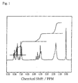
- the final product thus obtained was analyzed by measuring 1 H-NMR spectrum.
- the 1 H-NMR spectrum is shown in FIG. 1.
- the peaks in FIG. 1 support that the final product has the chemical structure expressed by the chemical formula (1-1) above.
- the final product was dissolved in chloroform and the ultraviolet ⁇ visible light absorption spectrum was measured. The results are shown in FIG. 2. It was confirmed from FIG. 2 that the final product had no absorption peaks in the visible light region, while on the other hand, it had the absorption peaks at 327nm in the ultraviolet light region. It was found from this fact that the chemical adsorption material synthesized in this Example was low in sensitivity to visible light and high in sensitivity to ultraviolet light.
- the coating film was formed by the following process.
- the glass substrate was immersed in the solution of the above-said chemical adsorption material being dissolved in a 1/5 mixed solution of xylene/KF96L (available from Shin-Etsu Chemical Co., Ltd.) to a concentration of 0.5 weight%, for about 2 hours. Thereafter, the substrate was taken out from the solution and its surface was fully washed by using chloroform in upstanding position to remove unreacted chemical adsorption material therefrom. Further, it was dried under air. The thin film was formed in this manner.
- FT-IR Fastier Transform Infrared Spectroscopy
- a liquid crystal cell (hereinafter it is called the test cell) was prepared in the manner that a substrate with a polarized light irradiated thin film is laid over another glass substrate with a gap of about 12 ⁇ m therebetween with its liquid thin film facing inwards and sealed around the margins thereof and, thereafter, nematic liquid crystal (available from Merck Industrial Chemicals, Brand name: ZL14792) is injected in the gap. Then, polarizing plates were arranged on both outside surfaces of the test cell, respectively. Then, the measurement was made of the capabilities of the thin film to align the liquid crystals by using visible light. It was confirmed from the measurement that the liquid crystal molecules in the cell are aligned uniformly in a certain direction.
- the surface of the substrate irradiated with the polarized light (the surface on the side opposite to the thin-film forming surface) was subjected to the rubbing. After the same surface of the substrate was heated at about 200°C for 1 hour, the liquid crystal cell was built up. Then, the measurement was made again on the orientation of liquid crystal molecules. It was confirmed from the measurement that the orientation of the liquid crystal molecules was not varied by those outside stimulus.
- the orientation of liquid crystals can be ascertained by the method of observing the polarized light (visible light) entering the test cell through the polarizing plate laid over one side of the test cell and passing through the cell in many directions.
- the chemical adsorption material silane-baced chemical adsorption material synthesized in the following is the compound expressed by the chemical formula (2-3) given below.
- the reactant thus obtained was poured into 3.4L of a 5% hydrochloric acid to extract the reaction product by using ethyl acetate and rinse it by using dilute hydrochloric acid. Then, the reaction product was dried by using magnesium sulfate anhydride and thereafter the solvent was distilled off to obtain crude crystals.
- reaction solution was poured into 2.1L of 1N hydrochloric acid and the deposited crystals were taken out by filtration.
- the final product was analyzed by measuring 1 H-NMR spectrum.
- the 1 H-NMR spectrum is shown in FIG. 3.
- the peaks in FIG. 3 support that the final product has the chemical structure expressed by the chemical formula (2-7) above.
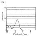
- the final product was dissolved in chloroform and the ultraviolet ⁇ visible light absorption spectrum was measured. The results are shown in FIG. 4. It was confirmed from FIG. 4 that the final product had no absorption peaks in the visible light region, while on the other hand, it had the absorption peaks at 327nm in the ultraviolet light region. It was found from this that the chemical adsorption material synthesized in this Example was low in sensitivity to visible light and high in sensitivity to ultraviolet light.
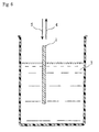
- the method for producing the liquid crystal alignment film will be described with reference to FIGS. 5 and 6.
- the surface of the glass substrate (including a number of hydroxyl groups) forming transparent electrodes thereon was well cleaned to remove grease to thereby finish the glass substrate 1.
- the (silane-based) chemical adsorption material synthesized in the above was dissolved in the mixed solvent of the well-dehydrated siloxane solvent (Brand name: KF96L, available from Shin-Etsu Chemical Co., Ltd.) and chloroform to a concentration of about 1 weight%.
- the solution was regarded as chemical adsorption solution 2.
- the glass substrate 1 was immersed in the chemical adsorption solution 2 in a dry atmosphere of relative humidity of 30% or less for about 1 hour, as shown in FIG. 5 (Process A). Thereafter, the glass substrate 1 was immersed in and taken out from the well-dehydrated chloroform 3 (aprotic solvent) to rinse the surface of the substrate, as shown in FIG. 7 (Process B). Thereafter, the glass substrate 1 was pulled up in the direction of an arrow 4 from the chemical adsorption solution 2 and then was stood upright to cut the cleaning solution, so as to be dried (Process C). Sequentially, the surface of the glass substrate 1 was exposed to the air charged with moisture (relative humidity of 50-80%) (Process D).
- the significance of the processes above is as follows.
- the process A in which the glass substrate 1 is immersed in the chemical adsorption solution 2 is for a SiCl group of chlorosilane chemical adsorption material and a hydroxyl group on the substrate to be subjected to de-HCl reaction. This process permits the chlorosilane chemical adsorption material to be strongly bonded to the surface of the glass substrate 1.
- the process B in which the glass substrate 1 pulled up from the chemical adsorption solution 2 is cleaned by the chloroform 3 is for removing the unreacted chemical adsorption material from the surface of the substrate. This process is necessary for forming the thin film of monomolecular layer form.
- the cleaning solution draining and drying process after cleansing is for allowing the adsorbing molecules to be aligned in a fixed direction.
- the substrate is set up orienting in a fixed direction to cut and dry the cleaning solution remaining on the thin film of the substrate, the adsorption molecules are tentatively aligned along the draining and drying direction.
- the glass substrate 1 is pulled up from the chemical adsorption solution after rinsing, it is set up vertically as it stands in the direction indicated by the arrow 5 in FIG. 6.
- the process D in which the substrate dried after the cleaning solution is cut is exposed to the air charged with moisture is the de-HCl reaction process to allow the remaining Cl of the SiCl group to react with the moisture in the air. This process permits the siloxane bond of the adsorption molecules.
- the monomolecular film 9 is formed which comprises chlorosilane chemical adsorption material siloxane-bonded to the hydroxyl groups on the substrate (in a tentatively aligned state).
- the monomolecular film 9 is a thin film in the monomolecular layer form which is formed as a unit of the chemical bond given by the following chemical formula (2-8).
- an alternative process may be adopted of applying the chemical adsorption solution 2 to the surface of the glass substrate 1.
- the alignment condition of the monomolecular film 9 was examined by means of the test cell.
- the test cell was produced in the following manner. Two substrates with monomolecular films 9 were produced. Then, they were superimposed with each other with a gap of about 12 ⁇ m in the condition in which their respective film surfaces face inwards and their respective film surfaces are so oriented that their solution draining directions are opposite to each other (in the anti-parallel condition) and then were sealed around the margins thereof. Thereafter, nematic liquid crystal ( ⁇ ⁇ of about -2 and ⁇ n of about 0.08) was injected in the gap and then the polarizing plates were arranged on both sides of the test cell, respectively. Then, the orientation of liquid crystal molecules was examined by the method that the visible light ray entering the polarizing plate from one direction is observed at many directions. It was confirmed from the measurement that the liquid crystal molecules were aligned along the solution draining and drying direction.
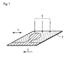
- FIG. 7 designates the solution draining and drying direction
- 6 designates a polarized ultraviolet light
- 7 designates a polarizing direction
- 8 designates transparent electrodes
- 9 designates an aggregation of adsorption molecules (monomolecular film).
- the monomolecular film 9 was subjected to the re-alignment process in the manner as shown in FIG. 7.
- the monomolecular film 9 was irradiated with 480mJ of a 365nm ultraviolet 8 of a 500W high-pressure mercury lamp (2.1mW/cm 2 after passing through the polarizing film).
- the chemical properties of the monomolecular film 9 as irradiated with the ultraviolet rays 8 was examined by use of FT-IR (Fourier Transform Infrared Spectroscopy). As a result of this, it was found that there was difference in IR absorption between the polarizing direction and the direction orthogonal thereto. Specifically, it was found that the IR absorption was significantly reduced in the polarizing direction, rather than in the direction orthogonal to the polarizing direction. The reduction of the IR absorption means that the chalcone skeleton was cross-linked at its carbon-carbon double bond portion by the optical energy in the polarizing direction. Hence, it was confirmed from this result that the irradiation of the polarized ultraviolet light enables the cross-link.
- FT-IR Fastier Transform Infrared Spectroscopy
- the liquid crystal cell was produced in the same manner as in the above-mentioned test cell by use of the substrate with the liquid crystal alignment film as was re-aligned. Then, it was put to the liquid crystal alignment test. The result was that when no voltage was applied to the liquid crystal cell, the light was hindered from transmitting through the cell to thereby produce the black display, while on the other hand, when the voltage of 3 volts was applied thereto, the light was permitted to transmit therethrough to thereby produce the white display. This means that the alignment of the liquid crystal molecules was converted into the homogeneous alignment from the homeotropic alignment through the application of voltage. Further, when the pretilt angle was measured by the magnetic field threshold method, it was confirmed that the liquid crystal molecules were aligned at the pretilt angle of about 89.5 degree.
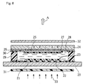
- Example 2-2 the substrate on which the pixel electrodes were arrayed in a matrix form was used, and the liquid crystal alignment film was formed on the substrate in the same manner as in Example 2-1. This substrate with the liquid crystal alignment film was used to produce a liquid crystal display. In the following, the producing process of the liquid crystal display of Example 2-2 will be described with reference to FIG. 8.
- the chemical adsorption solutions which were prepared in the same manner as in Example 2-1 were made to contact with (i) a first substrate 23 having thereon a first group of transparent electrodes 21 arranged in a matrix form and a group of transistors 22 to drive the first group of electrodes and (ii) a second substrate 26 having thereon a group of color filters 24 and a second group of transparent electrodes 25 (common electrodes), respectively. Further, they are subjected to a series of processes of the solution draining and drying process and the polarized irradiation process to thereby produce the substrates 23, 26 with liquid crystal alignment films.
- Example 2-1 When the alignment properties of the alignment films of the substrates 23, 26 with liquid crystal alignment films were examined in the same manner as in Example 2-1, it was found that the liquid crystal alignment film 27 in which the liquid crystals were re-aligned along the electrode pattern was produced. Then, the substrates 23, 26 with liquid crystal alignment films were adapted to render the alignment of the liquid crystal alignment film homeotropic. Then, they were superimposed with each other, with a cell gap of 4.5 ⁇ m formed between the substrates by spacer 28 and adhesive 29, to thereby produce the liquid crystal cell.
- nematic liquid crystal ( ⁇ ⁇ of about -3 and ⁇ n of about 0.09) 30 was injected in the cell gap and the cell was fully sealed. Thereafter, the polarizing plates 31, 32 were combined with the cell to complete the liquid crystal display.
- the pretilt angle of the liquid crystal molecules in the liquid crystal display was measured by the magnetic field threshold method, it was about 89.8 degree.
- the liquid crystal display was driven by video signals, while the liquid crystal display was irradiated with backlight 33 from the back thereof, it was confirmed that it could display a clear picture with respect to the direction of arrow A.
- the liquid crystal alignment film was formed on the substrate in the same manner as in Example 2-2, except that the chemical adsorption material used was a mixed solution formed by phenyltrichlorosilane and fluorochemical adsorption material used in Example 1 (4-(2,2,3,3,3,-Pentafluoropropyloxy)-4'-(6'-trichlorosilyloxyhexyloxy)chalcone) being mixed at a mixing ratio of 9:1.
- the liquid crystal alignment film thus produced was measured on the pretilt angle of the liquid crystal molecules by the crystal rotation method. The result was that the pretilt angle was 8.5 degree.
- the liquid crystal display was produced in the same manner as in Example 2-2.
- the liquid crystal material used was nematic liquid crystal whose ⁇ ⁇ was about 2.3 and ⁇ n was about 0.26. Further, when the liquid crystal display was driven by use of video signals, while the liquid crystal display was irradiated with backlight from the back thereof, it was confirmed that it could display a clear picture.
- liquid crystal alignment film having good controllability of alignment of liquid crystals and having the capabilities of controlling the liquid crystals at a desired pretilt angle and displaying clear picture could be provided by mixing the two different chemical adsorption materials.
- Example 2-4 In the irradiation of polarized ultraviolet light after the tentative alignment, a pattern-like mask for dividing each picture element into four regions in a checkered pattern was laid over the polarizing plate and then was exposed to light at one time, to thereby produce a multi-domain type liquid crystal alignment film having four divided regions different in orientation for the liquid crystals to be aligned in patterns within the same picture element. Except this condition, the multi-domain type liquid crystal display according to Example 2-4 was produced in the same conditions as in Example 2-2.
- Example 2-2 When the liquid crystal display was driven by use of video signals in the same manner as in Example 2-2, it was confirmed that it could display a picture of a wide viewing angle, as compared with the case of Example 2-2.
- the two comb electrodes meshed with each other in a non-contact state were disposed on the same plane of a single substrate and then the liquid crystal alignment film as was subjected to the re-alignment process was further formed on those electrodes in the same manner as in Example 1.
- the chemical adsorption solution used was a mixed solution formed by fluorochemical adsorption material synthesized in Example 1 (4-(2,2,3,3,3,-Pentafluoropropyloxy)-4'-(6'-trichlorosilyloxyhexyloxy)chalcone) and the chemical adsorption material in which the fluorine was not contained in the fluorochemical adsorption material synthesized in Example 1 being mixed at a mixing ratio of 1:29.
- the opposite substrate was superimposed with the substrate with the liquid crystal alignment film to form the liquid crystal cell in the usual way to thereby produce an in-plane switching (IPS) mode of liquid crystal display.
- IPS in-plane switching
- the picture display test was conducted by using video signals in the same manner as in Example 2-2 or Example 2-4. It was confirmed from this test that the picture was displayed with an expanded viewing angle.
- the novel chemical adsorption material of the invention comprises a functional group having at one end thereof a functional group of very small critical surface tension and at the other end thereof a functional group capable of strong chemical bond to a hydrophilic group on the surface of the substrate, and a photosensitive group. Consequently, according to the present invention, a thin film of a monomolecular layer form can be formed on the surface of the base substance with ease.
- the thin film is stable and transparent in the visible light region and also excellent in water repellency and durability, so that it is useful as a functional coating film for modification of surface property.
- the chemical adsorption material of the present invention can allow the adsorption molecules to be cross-linked to each other in a specific direction by the process that the chemical adsorption material is chemically adsorbed to the surface of the base substance and thereafter is irradiated with polarized ultraviolet light. This can produce the liquid crystal alignment film having strong and stable alignment properties.
- the chemical adsorption material mentioned above can be produced with efficiency.
- the novel thin-film forming chemical adsorption material that is useful as a surface property modifying agent for a base substance, or particularly useful as the material of the liquid crystal alignment film. Consequently, industrial significance of the present invention is great.
- the liquid crystal alignment film of far small in thickness and uniform in alignment, as compared with the conventional organic polymer liquid crystal alignment film. Also, since the liquid crystal alignment film has the structure in which the adsorption molecules are strongly bonded and anchored on the surfaces of electrodes via the chemical adsorption and also are cross-linked to each other, it is excellent in adhesion to the substrate and also is resistant to deterioration of the alignment properties resulting from external factors such as heat and friction.
- the thin film of a monomolecular layer form comprising the aggregation of adsorption molecules has significantly advantageous properties as the liquid crystal alignment film that it does not hinder the transmission of light due to its excellent transmission of the visible light and that it does not hinder the electric field to drive the liquid crystals due to its small electrical resistance.
- the multi-domain type liquid crystal alignment film of different in orientation for the liquid crystals to be aligned in each of the regions divided to a pattern can be reliably and efficiently produced by a relatively simple technique simply using the solution draining and drying process and the irradiation of polarized light.
- the applications of the liquid crystal alignment film according to the present invention can provide the homeotropic alignment mode of multi-domain type liquid crystal display having wide viewing angle, high picture quality, high contrast and excellent high-speed response with little increase of costs.
Landscapes
- Chemical & Material Sciences (AREA)
- Organic Chemistry (AREA)
- Physics & Mathematics (AREA)
- Engineering & Computer Science (AREA)
- Nanotechnology (AREA)
- Crystallography & Structural Chemistry (AREA)
- General Physics & Mathematics (AREA)
- Materials Engineering (AREA)
- Composite Materials (AREA)
- Condensed Matter Physics & Semiconductors (AREA)
- Nonlinear Science (AREA)
- Chemical Kinetics & Catalysis (AREA)
- Spectroscopy & Molecular Physics (AREA)
- Mathematical Physics (AREA)
- Optics & Photonics (AREA)
- Liquid Crystal (AREA)
Abstract
A thin film forming chemical adsorption material of the present
invention includes at least a functional group expressed by the following
chemical formula and a -SiX group (X represents halogen) as an end group
bonded by siloxane bond. Consequently, a novel, thin-film forming,
chemical adsorption material which is capable of forming a thin-film of a
monomolecular layer form and has photosensitive groups which are
transparent and stable in a visible light region and cause photochemical
reaction in a ultraviolet light region, and the producing method thereof can
be provided.
The liquid crystal alignment film of the present invention includes an
aggregation of adsorption molecules chemically adsorbed directly on a
surface of a substrate with electrodes or chemically adsorbed indirectly
thereon through another material layer, and further the adsorption
molecules include adsorption molecule having a characteristic group
expressed by the following chemical formula and a -O-Si bond group at a
molecular end group. Consequently, the liquid crystal alignment film that
is uniformly and strongly anchored on the substrate, is excellent in thermal
stability of alignment as well as in controllability of alignment, and has a
film thickness of such a level of nanometer as to be produced with good
productivity, and the LCD using the same can be provided.

Description
The present invention relates to a chemical adsorption material to be
chemically adsorbed on a surface of a substrate to form a thin film thereon
and to a producing method thereof. More particularly, the present
invention relates to a chemical adsorption material used mainly as liquid
crystal alignment film coating material for forming a thin film and to a
producing method thereof. Also, the present invention relates to an
organic thin film formed by use of the thin film forming chemical adsorption
material and to a producing method thereof. Further, the present
invention relates to a liquid crystal alignment film and to a producing
method thereof. Furthermore, the present invention relates to a liquid
crystal display using the same and to a producing method thereof and,
further particularly, to a liquid crystal alignment film for use in a plane
display panel using liquid crystals to display television (TV) picture,
computer picture and the like, to a producing method thereof, and to a
liquid crystal display device using it.
In recent years, liquid crystal elements come into wide use rapidly as
means for miniaturization of information technology equipment. A liquid
crystal alignment film which is the critical component of the liquid crystal
elements is subjected to a rubbing process which can be cited as a typical
alignment film treatment process. However, the rubbing process has
difficulties of deterioration of display quality caused by generation of fine
dusts and rubbing lines and others. To avoid these difficulties, rubbingless
alignment film treatments, such as an optical alignment film treatment, are
now under study.
Known optical alignment film treatments include the process that an
alignment film made of polymer, such as polyimide or polyvinyl alcohol, is
irradiated with polarized ultraviolet light for alignment film treatment.
Another approach was also reported (by Japanese Patent Application No.
Hei 8-224,219), in which the optical alignment film treatment is given to
the optical alignment film comprising chemical adsorption monomolecular
film, as well as to that of polymer such as polyimide. The optical
alignment film treatment is performed under the alignment mechanism
that admolecules of the film are irradiated with polarized light so as to be
re-aligned, so that the liquid crystal molecules are aligned along the
polarization direction.
In the case of the alignment film comprising polymer, it has the
molecular structure that polymers are complicated densely and irregularly,
except its surface part. Because of this, only a part of a surface of the film
from which tip portions of the polymer projects out can contribute to the
alignment of the liquid crystal molecules. In addition to this, because of
uncertainty of the alignment orientation of the side chain, the functional
group contributive to the alignment is not always exposed on the surface.
Consequently, the part thereof contributive to the alignment of the liquid
crystal molecules is obviously smaller in density than that of the
monomolecular film, thus suffering the disadvantage that it is difficult to
make an adequate control of alignment of the liquid crystals. Also, since
the alignment film comprising polymer has large thickness and thus
insulative property, it has the problem that transmission of light and
electric field to drive the liquid crystal molecules are hindered.
In contrast to this, in the case of the alignment film comprising
chemical adsorption monomolecular film, since the functional group
contributive to the alignment of the liquid crystal molecules is fully exposed
on the surface of the film, adequate control of alignment of the liquid
crystals can be obtained. In addition to this, the alignment film of
chemical adsorption monomolecular film is in a monomolecular layer form
and thus has small thickness, as compared with the alignment film of
polymer. Also, since it is chemically adsorbed on the surface of the
substrate, it also has excellent adhesion property.
Thus, the conventional alignment film comprising polymer has the
problems that adequate control of alignment cannot be obtained and that it
has large thickness and thus insulative property. In view of the problems
above, there has been developed and provided an alignment film comprising
chemical adsorption monomolecular film.
The alignment film comprising chemical adsorption monomolecular
film was rather useful for solving the disadvantages mentioned above.
However, the admolecules forming the film are merely aligned and arrayed
along the polarization direction, so that when the film is heated to high
temperature, the alignment stability falls disadvantageously.
Consequently, the development is being desired of a useful alignment film
of monomolecular film form that is further excellent in thermal stability of
alignment.
Incidentally, the conventional liquid crystal display has the structure
wherein a pair of substrates, which have transparent electrodes arranged in
a matrix form and liquid crystal alignment films formed on the transparent
films, are arranged to confront each other, with a given gap therebetween
with their liquid crystal alignment films facing inwards, and liquid crystal
is sealed in the gap. Now, taking a color liquid crystal display as an
example, a typical producing method will be explained below. A polymer
membrane is formed on each of a first glass substrate on which pixel
electrodes and thin-film transistor (TFT) array are formed and a second
glass substrate on which a number of color filters of red, blue and green are
formed and common transparent electrodes are further formed thereon.
Then, these polymer-coated surfaces of the substrates are subjected to the
rubbing to provide alignment characteristic of liquid crystal. Then, the
substrates are so arranged that their coated surfaces can face inward and
confront each other in the state in which spacers are interposed
therebetween and are adhesive bonded around the margins thereof to form
an empty cell (a panel structure).
Liquid crystal material, such as twisted nematic liquid crystal, is filled
in and tightly sealed in the empty cell, to form the liquid crystal display
element. Further, a polarizing plate is arranged on each outside surface of
the element and also a backlight is disposed at the outside of the first glass
substrate, to thereby produce the liquid crystal display as the optical
display element.
In the liquid crystal display thus structured, the TFT of switching
elements controls an interelectrode voltage to change the alignment of
liquid crystals, so that the transmission of light is switched on and off on a
pixel basis to display any desired image. Consequently, the alignment film
that controls the alignment of the liquid crystals at the time of no applied
voltage bears a significantly important part in exerting an influence
directly on the display performance of the device.
Polyimide films have been widely used hitherto as a coating material
of the liquid crystal alignment film, in terms of their excellence in affinity to
liquid crystal, heat resistance, and adhesion to the substrate. In general,
the polyimide film is produced by using either of the following two processes.
One is that after liquid solution obtained by polyamic acid of precursor
polymer of polyimide being dissolved in organic solvent such as xylene is
rotationally applied on to the substrate, that substrate is baked to imidize
the polyamic acid, so as to form the polyimide film. Another is that after
liquid solution obtained by polyimide itself being dissolved in organic
solvent such as DMF (N,N-dimethylformamide), DMAc
(dimethylacetamide), butyl cellosolve acetate and N-methyl-2-pyrrolidone is
rotationally applied on to the substrate, the solvent is evaporated to form
the coating film. The polyimide film thus produced has the following
problems, however.
When the polyimide film involving the various problems mentioned
above is used as the liquid crystal alignment film and is subjected to the
alignment process such as the rubbing process, additional problems are
further caused as follows.
1 ○ When the coating film has projections and depressions, it cannot be
rubbed at its depressed part. The coating film particularly for a larger
area panel would not be rubbed uniformly, so that the problems, such as
deficiency in alignment, display unevenness and display burn-in, are
caused.
2 ○ Static electricity is generated on the alignment film, and as such
can cause a possible lowering of the TFT function.
3 ○ Further, dust is produced from rubbing material (cotton cloth and
the like), and the dust accounts for variations of display unevenness and the
gap between the substrates.
These problems become outstanding particularly in the following
cases. For example, Japanese Laid-open (unexamined) Patent Publication
No. Hei 5-173,135 proposes the method wherein the process that the
alignment film is rubbed in a certain direction and further is rubbed in the
opposite direction after the concerned part is covered with resist is repeated
a given number of times to form a number of areas varied in orientation of
alignment of liquid crystal. This method produces the effect in providing a
modified viewing angel characteristic to the TN mode of liquid crystal
display element having its inherent disadvantage of narrow viewing angle.
However, the complicated work that the masking is done for each of divided
regions in advance of the rubbing must be repeated, in order to form a
number of divided areas varied in orientation of alignment of liquid crystal.
This causes the production efficiency of the alignment film to be lowered to
a large extent and also causes the dust generation problem into further
serious problem.
Under the circumstances, various non-contact alignment modes have
been proposed with the aim of solving the problems involved in the rubbing
mode.
For example, Japanese Laid-open (unexamined) Patent Publication
No. Hei 5-53,118 proposes the technique that a photosensitive composition
layer is formed on the substrate and then grooves in specific patterns are
formed on the composition layer through the exposure and heating
processes, so that the alignment of liquid crystal is provided by the grooves
thus formed. However, this technique requires large light energy for
forming the grooves. Further, it is difficult for the grooves to be formed
uniformly, thus causing the problems of display unevenness and the like.
Furthermore, it has the problem that the control of the alignment of liquid
crystal is not sufficient.
Japanese Laid-open (unexamined) Patent Publication No. Hei 7-72,483
proposes the technique that the alignment film forming compound
layer including polyimide or precursor of polyimide is directly irradiated
with polarized light to polymerize the polyimide and the like, so as to
provide the alignment of liquid crystal. However, since this technique uses
the polyimide of organic polymer, if the alignment film has large thickness,
the problem of increased liquid crystal driving voltage cannot be solved.
Further, the technique has an additional problem that anchoring strength
of the alignment film to the substrate is insufficient.
Japanese Laid-open (unexamined) Patent Publication No. Hei 7-318,942
proposes the technique that the alignment film having the polymer
structure is obliquely irradiated with light to cause additional bond or
decomposing reaction of molecular chains of the alignment film to thereby
produce the molecular structure having the alignment of liquid crystal.
However, this technique is intended for the alignment film comprising
organic polymer, such as polyimide, polyvinyl alcohol and polystyrene.
Accordingly, this technique cannot dissolve the above-noted problems of the
large film thickness, the small anchoring strength of the alignment film for
the substrate, and others, either. Also, it is essential for this technique
that the alignment film for which a pretilt angle is given is irradiated with
light from an oblique direction. However, in order for the alignment film
to be accurately irradiated with light from such an oblique direction, a
high-precision light irradiation device is required and accordingly the
production costs increase to that extent.
Applications of the techniques described by the publications as noted
above could form a number of divided areas varied in orientation of
alignment of liquid crystal and accordingly could also apply to the TN mode
of liquid crystal display element having a narrow viewing angle. However,
since the respective techniques have the problems of the large film
thickness, the small anchoring strength of the alignment film for the
substrate, and others, as mentioned above, the applications thereof could
not provide a fully satisfactory liquid crystal alignment film, after all.
On the other hand, a VA (vertical alignment) mode of liquid crystal
display capable of realizing high contrast and high-speed response have
begun to make a mark in recent years. In this alignment mode, the
vertical alignment of liquid crystal molecules can be realized by use of a
VA-use liquid crystal alignment film. The VA-use liquid crystal alignment
films include the one formed by the polyimide, in which a long-chain alkyl
group or a fluoric functional group is introduced into the side chain, being
used as the alignment film material. However, such alignment film
material is, in general, high in surface energy (e.g. low in water repellency),
thus suffering the problem of being inferior in adhesion to the substrate.
In addition, since the alignment film is formed of polymer, it is large and
uneven in thickness and thus has insulative property, thus suffering the
aforementioned problem that transmission of light and electric field to drive
the liquid crystal molecules are hindered. Further, although the action of
the side chain is the factor contributing to the vertical alignment of the
liquid crystal molecules, it is impossible to make the control of allowing the
side chain to be efficiently exposed on the boundary between the side chain
and the liquid crystal. For this reason, the part of the alignment film to
contribute to the alignment of the liquid crystal molecules is apparently low
in density, as compared with the monomolecular film, thus suffering the
difficulties of adequate control of alignment of liquid crystals.
Meanwhile, in Japanese Laid-open (unexamined) Patent Publication
No. Hei 3-7,913 the inventors previously proposed the technique for
producing the alignment film having thickness of a level of nanometer with
efficiency. This technique uses the monomolecular layer, which is formed
by silane-baced chemical adsorption material (which is also called the
surface-active agent) being chemically adsorbed on the substrate as the
alignment film. This technique can produce the result that a very thin
transparent coating film bonded and anchored on the substrate can be
formed with ease and efficiency. Besides, it can provide the alignment film
having some capability of controlling alignment of liquid crystal molecules
without any rubbing process. This technique still has room for
improvement on the thermal stability of the alignment and the
controllability of the alignment, however.
In consideration of the present situation mentioned above, a group of
inventions have been made. It is the primary object of the invention to
provide a novel, thin-film forming, chemical adsorption material which is
capable of forming a thin-film of a monomolecular layer form and has a
photosensitive group which is transparent and stable in a visible light
region and causes photochemical reaction in a ultraviolet light region and
also provide the producing method thereof.
It is the secondary object of the invention to provide a novel, vertical
alignment-use, liquid crystal alignment film having a very small thickness
of a level of nanometer that can be uniformly and strongly anchored on the
substrate, is excellent in thermal stability and controllability of alignment
and wide in viewing angle, capable of high-response and high-contrast
control of alignment via the vertical alignment, and can be produced with
good productivity and to provide a novel liquid crystal display element
using such a liquid crystal alignment film.
Although the group of inventions is based on the same or similar
conception, since they are realized by way of different examples, the
inventive groups are divided into the first inventive group, the second
inventive group and the third inventive group on the basis of their
respective relevance. In the following, the contents will be explained in
order for each division (each inventive group).
The inventors of this application have discovered that chemical
adsorption material having a chalcone skeleton can be chemically adsorbed
on the base substance to form a transparent coating film of a
monomolecular layer form and also it has reactivity to light in a far
ultraviolet ultraviolet light (of wavelength of 200nm to 400nm) region,
while on the other hand, it exhibits stability to light in a visible light (of
wavelength of 400nm to 700nm) region, and further have made an analysis
thereon. As a result of the study, they have completed a novel, thin-film
forming, chemical adsorption material (hereinafter it sometimes simply
referred to as chemical adsorption material) and a producing method of this
chemical adsorption material.

In order to attain the primary object mentioned above, an organic thin
film according to the first inventive group comprises at least a functional
group expressed by the following chemical formula (1-1) and a -SiX group (X
represents halogen) as an end group bonded by siloxane bond:
The functional group expressed by the chemical formula (1-1) includes
the chalcone skeleton expressed by the following chemical formula (1-4), so
that when the functional group is irradiated with light in the ultraviolet
light region, it functions as a photosensitive group and permits the
molecules to be cross-linked to each other.
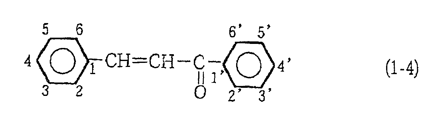
Further, since a perfluoromethyl group (-CF3 group) represented in
the chemical formula (1-1) has the minimum critical surface tension of all
atoms and groups, so it has the property of repelling the liquid crystals.
Also, according to the thin film forming chemical adsorption material
having the above-noted constitution, since there is included a SiX group as
an end group bonded by the siloxane bond, the Si portion functions as the
chemical adsorption group and is allowed to react with a functional group
existing on the surface of the base substance to be chemically adsorbed
thereon.
The compound expressed by the following chemical formula (1-2) is
preferably used as the chemical adsorption material.

The thin film forming chemical adsorption material having these
properties is useful as a functional coating film material for modifying the
property of the surface of the base substance, particularly as a liquid crystal
alignment film material. For example, when the thin film forming
chemical adsorption material is used as the liquid crystal alignment film
material, the following operation and effect are provided. The thin film
formed by putting the chemical adsorption material into contact with the
base substance so as to be chemically adsorbed thereon has the structure of
a monomolecular layer form in which molecules are arranged laterally, with
their one long axial ends (SiX groups) being bonded to the surface of the
base substance and the other ends being oriented to a direction for them to
be away from the base substance. This coating film is of very thin of a
level of nanometer and is chemically stable and transparent in the visible
light region.
On the other hand, since the chemical adsorption material has the
properties that a vinyl group portion causes a light reaction by the
irradiation of light in the ultraviolet light region, when the chemical
adsorption material as was chemically adsorbed on the base substance is
irradiated with ultraviolet light, the adsorption molecules is cross-linked to
each other. This can provide the liquid crystal alignment film in which the
alignment of the adsorption molecules are strically stabilized. Also, when
polarized light is used in the irradiation of ultraviolet light, a cross-link
reaction can be caused along a specific direction. Accordingly, when the
polarizing direction is regulated, the orientation for the adsorption
molecules to be aligned can be controlled.
It is to be noted here that with the thin film of a monomolecular layer
form having the structure that the chemical adsorption material is adsorbed
along the base substance, it is possible for the liquid crystal molecules to
enter the spaces (valleys) between the individual adsorption molecules.
Consequently, the thin film in which thin film constituent molecules
(adsorption molecules) are aligned in a given direction has a specific
orientation of liquid crystals. With this thin film, since the constituent
molecules of the thin film are each contributive to the orientation of liquid
crystals, although the film is a very thin coating film of a monomolecular
layer form, it exerts strong control of alignment of liquid crystals. Further,
since the end group of the thin film constituent molecule on the front side of
the thin film is a perfluoromethyl group having a very small critical surface
tension, the liquid crystal molecules can be aligned at a high pretilt angle.
Also, since the adsorption molecules are linked and bonded to each other by
the cross-link reaction, the alignment properties are prevented from being
deteriorated due to external factors such as heat and friction.
In addition, since this coating film is very thin and transparent and
also is not an organic polymer film, it hardly serves as an electric resistance
film. Consequently, it has significantly advantageous properties as the
liquid crystal alignment film that it does not hinder the transmission of
light and the electric field to drive the liquid crystals.
In contrast to this, in the conventional liquid crystal alignment film
(e.g. a polymer film made of polyimide) in which the long chains are densely
and irregularly complicated, only a surface part thereof is contributive to
the alignment of the liquid crystals, so that it is hard to obtain adequate
controllability of the alignment of the liquid crystals. In the conventional
alignment film having the alignment property given by the rubbing, the
alignment property is varied or deteriorated by external factors such as
heat and friction. Further, since the polymer film made, for example, of
polyimide is large in thickness and high in electric resistance, it provides
inhibition factors to hinder the transmission of light and the electric field to
drive the liquid crystals.
The chemical adsorption material of the present invention can be
produced by a producing method comprising at least:
the chemical reaction process 1 that at least 4-(2,2,3,3,3-Pentafluoropropyloxy) benzaldehyde and 4-Hydroxyacetophenone are subjected to aldol condensation reaction to synthesize alcohol having a chalcone skeleton expressed by the following chemical formula (1-3) (chemical reaction process 1); and thechemical reaction process 2 that after
the chemical reaction process 1, SiX4 (X represents halogen) is subjected to
dehydrohalogenation reaction with alcohol having the chalcone skeleton
under an inert gas atmosphere, to synthesize chemical adsorption material
having a characteristic group expressed by the following chemical formula
(1-1) and a -O-SiX3 group:


the chemical reaction process 1 that at least 4-(2,2,3,3,3-Pentafluoropropyloxy) benzaldehyde and 4-Hydroxyacetophenone are subjected to aldol condensation reaction to synthesize alcohol having a chalcone skeleton expressed by the following chemical formula (1-3) (chemical reaction process 1); and the
This can produce the chemical adsorption material that can permit the
molecules to be cross-linked with each other and also allow them to react
with the surface functional group existing on the surface of the base
substance so as to be chemically adsorbed thereon when irradiated with the
light in the ultraviolet light region.
Further, the chemical adsorption material include a compound
expressed by the following chemical formula (1-2):

In order to attain the secondary object mentioned above, an organic
thin film according to the secondary inventive group comprises an
aggregation of adsorption molecules directly bonded and anchored to or
indirectly bonded and anchored to a surface of a base substance through
another material layer, wherein the adsorption molecules have a
characteristic group expressed by the following chemical formula (2-1) and a
-O-Si bond group at a molecular end group:

The organic thin film having the constituent mentioned above
comprises the aggregation of adsorption molecules arrayed along the
surface of the base substance in the state in which they are chemically
adsorbed on the base substance at one end thereof (on the -O-Si bond group
side) and are projected out from the surface of the base substrate in a
direction of being away therefrom. In the aggregation of adsorption
molecules comprising the characteristic group expressed by the chemical
formula (2-1) and the -O-Si bond group, since the individual adsorption
molecules are strongly bonded and anchored to the substrate via the
chemical bonding, the peeling of the coating film is prevented.
Consequently, it has an excellent anti-peeling property.
When this organic thin film is applied to the liquid crystal alignment
film, the liquid crystal molecules can enter the spaces (valleys) between the
adsorption molecules in the aggregation of adsorption molecules and are
then controlled to the tilt and/or orientation of alignment of the liquid
crystals with respect to the substrate (hereinafter it is collectively called the
alignment direction). Consequently, although the film is a very thin
coating film of a monomolecular layer form, it exerts strong control of
alignment of liquid crystals. Further, since it has a perfluoromethyl group
(-CF3 group) having a very small critical surface tension as the end group of
the thin film constituent molecule on the front side of the thin film, the
liquid crystal molecules can be aligned at a high pretilt angle. Also, since
the liquid crystals can strongly be bonded to the substrate through Si atoms
and also the adsorption molecules can strongly be bonded to each other
through Si, the liquid crystal alignment film of excellent durability can be
obtained.
The base substances that may be used include, for example, a
substrate made of glass and the like and those made of metal, ceramics,
glass, plastics, polymer, paper, fiber and leather. Further, electrodes
(including wires) and/or other material layers may be formed on the
substrate.
The adsorption molecules forming the organic thin film may be
molecules in which the chalcone skeleton of the functional group shown in
the chemical formula (2-1) and -O-SiX group are directly bonded to each
other or the functional groups cited below as an example are indirectly
bonded to the chalcone skeleton via the -O- bond.
The adsorption molecules explained above include those having the
chemical constituent expressed, for example, by the following chemical
formula (2-2):

The aggregation of adsorption molecules is permitted to be aligned in
a given direction. When the organic thin film is used as the liquid crystal
alignment film, this can provide a uniform liquid crystal alignment
property to the liquid crystal alignment film.
In this constituent, the adsorption molecules in adjoining divided
regions may be differentiated from each other in tilt of their major exes with
respect to the surface of the substrate and/or in orientation of alignment
thereof. The divided regions means the regions formed by dividing a single
picture element into a number of regions in a pattern-like form. When the
film is formed as the so-called, multi-domain type liquid crystal alignment
film in which the alignment direction of the adsorption molecules are
controlled in each of the minute regions into which the one picture element
is divided in a pattern, the light transmitting in each picture element is
formed by a number of bundles of rays different in angle from each other.
Thus, the dependency of the display on the viewing angle is reduced.
In the constituent above, the adsorption molecules of the aggregation
of adsorption molecules may be cross-linked to each other via a boning
line(s) of C' and/or C" in the chemical formula (2-1) or (2-2). Since the
adsorption molecules are strongly anchored to each other via the cross-link
bond, the tilt and the alignment direction of the adsorption molecules are
prevented from being varied by external factors such as friction and heat.
Consequently, the organic thin film having high reliability can be obtained.
In the constituent above, the organic thin film may have film
thickness of 0.5nm or more to less than 10nm. With the film thickness of
this range, the efficiency of alignment is high in the relation with the film
thickness and also the transmission of light and the electric field are not
unnecessarily hindered. Consequently, when the organic film is applied to
the liquid crystal alignment film, the usability is further improved.
In the constituent above, the organic thin film may be formed by a thin
film of a monomolecular layer form. The thin film of a monomolecular
layer form can provide the result that when applied to the liquid crystal
alignment film, the individual adsorption molecules are directly
contributive to the alignment of the liquid crystal molecules. Thus, the
liquid crystal alignment efficiency is considerably improved in the relation
with the film thickness.
In the constituent above, the organic thin film may comprise an
aggregation of adsorption molecules of various kinds. The organic thin
film comprising the aggregation of adsorption molecules of various kinds
can produce the organic thin film having multifunction.
When the organic thin firm is applied to the liquid crystal alignment
film, that liquid crystal alignment film can become an alignment film that
develops a desired pretilt angle for the liquid crystal molecules.
In the constituent above, the liquid crystal alignment film may
comprises the aggregation of adsorption molecules of various kinds, and the
liquid crystal molecules may be aligned at a desired pretilt angle by
changing a constituent ratio between the various kinds of adsorption
molecules.
It is to be noted here that in addition to the adsorption molecules
having a characteristic group expressed by the chemical formula (2-1) and a
-O-Si bond group at a molecular end group, the adsorption molecules that
may be used include, for example, adsorption molecule having a -O-Si group
and a long chain alkyl group (number of carbon: 7 or more to 18 or less) and
adsorption molecule having a -O-Si bond group and a long chain
fluorocarbon group (number of carbon: 7 or more to 18 or less). In addition,
the adsorption molecule in which a cyano group, an ester group, a chloro
group or a bromo group is bonded to an end of the alkyl group and
fluorocarbon group can also be cited. Further, these adsorption molecules
may be adsorption molecules having a characteristic group expressed by the
chemical formula (2-1).
Next, the producing method of the organic thin film of the present
invention will be described. The inventive producing method of an organic
thin film comprising an aggregation of adsorption molecules directly bonded
and anchored to or indirectly bonded and anchored to a surface of a base
substance through another material layer via chemical adsorption, the
producing method comprising: the process that chemical adsorption
material having a characteristic group expressed by the following chemical
formula (2-1) and a -O-Si bond group at a molecular end portion thereof is
at least dissolved in non-water-borne solvent, to prepare chemical
adsorption solution: the process that the chemical adsorption solution is put
into contact with the surface of the base substance, so that the chemical
adsorption material in the chemical adsorption solution is chemically
adsorbed on the surface of the base substrate; and the solution draining and
drying process that the surface of the base substance to which the chemical
adsorption material was bonded is cleaned by use of the non-water-borne
solvent and, thereafter, the base substance is stood up in a specific direction
to cut and dry the cleaning solution:

The producing method above may further comprises the polarized
ultraviolet irradiation process that after the solution draining and drying
process, the adsorption molecules on the surface of the base substance are
irradiated with polarized ultraviolet light, so that they are cross-linked to
each other via a bonding line of a carbon-carbon double bond portion of the
chemical formula (2-1).
The producing method above may be so constituted that a series of
alignment film treatment processes comprising the solution draining and
the drying process and a polarized ultraviolet irradiation process are
repeated a number of times in such a manner that the solution draining and
drying process returns back again from the polarized ultraviolet irradiation
process, and each time when repeated, the solution draining and drying
direction is varied and that the polarized ultraviolet light irradiation region
and polarized ultraviolet light irradiation direction, or the polarized
ultraviolet light irradiation region and polarized ultraviolet light
irradiation angle, or the polarized ultraviolet light irradiation region,
polarized ultraviolet light irradiation direction and polarized ultraviolet
light irradiation angle, are varied, whereby the adsorption molecules are
varied in tilt of their major exes with respect to the surface of the base
substance and/or in orientation of alignment thereof from one divided
region to another of a number of divided regions into which a region
corresponding to one picture element is divided in a pattern-like form.
This constitution enables the organic thin film suitable for the multi-domain
alignment to be produced reliably and with improved productivity.
In the producing method, aprotic solvent may be used as the non-water-borne
solvent for use in cleaning so that unreacted chemical
adsorption material can be cleaned and removed from the surface of the
base substance by use of the aprotic solvent, to produce a thin film of a
monomolecular layer form.
Alternatively, a mixed solvent of aprotic solvent and protic solvent
may be used as the non-water-borne solvent for use in cleaning, so that
unreacted chemical adsorption material can be cleaned and removed from
the surface of the base substance by use of the mixed solvent, to produce a
thin film of a monomolecular layer form. The use of the mixed solvent is of
desirable in that the chemical adsorption material dissolving capability and
evaporation speed can be adequately adjusted.
The significance of the constitutions above will be described. When
the solution of the chemical adsorption material having the characteristic
group expressed by the chemical formula (2-1) and the -O-Si bond group at
a molecular end portion thereof is put into contact with the substrate, the
chemical adsorption material is allowed to react with the surface functional
group having active hydrogen on the surface of the substrate to be
chemically adsorbed thereon, so as to form an organic thin film. The
organic thin film comprises the aggregation of adsorption molecules whose
one long axial ends (-O-Si bond group) are bonded to the surface of the base
substance and whose other ends are oriented to a direction for them to be
away from the base substance. When this organic thin film comprising the
aggregation of adsorption molecules is applied to the liquid crystal
alignment film, the liquid crystal molecules can enter the spaces (valleys)
between the adsorption molecules and are then controlled to the alignment
direction of the liquid crystal molecules with respect to the substrate.
Consequently, the alignment direction of the liquid crystal molecules can be
controlled by regulating the alignment direction of the adsorption
molecules.
On the other hand, the compound having the characteristic group
expressed by the chemical formula (2-1) has the properties that it is
transparent and chemically stable in the visible light region and also high
in sensitivity to ultraviolet light at the carbon-carbon double bond portion
thereof. Consequently, when the adsorption molecules are chemically
adsorbed on the substrate and then are irradiated with ultraviolet light,
they can be cross-linked to each other through the carbon-carbon double
bonding. In this process, when the polarized ultraviolet light is used, the
cross-link direction can be controlled to a specific direction corresponding to
the polarizing direction of the polarized light. Then, the adsorption
molecules on the surface of the substrate are re-aligned by the irradiation of
the polarized light and the re-alignment is provided by the molecules being
cross-linked to each other, and as such can produce the resistance to the
external factors such as heat and friction.
The chemical adsorption material having the characteristic group
expressed by the chemical formula (2-1) and the -O-Si bond group at a
molecular end portion thereof that may be used include a compound
expressed by the following chemical formula (2-2).

The chemical adsorption material expressed by the chemical formula
(2-2) can be chemically adsorbed on the surface of the base substance with
ease. Also, the material is strong in bond and high in light-sensitivity at
the carbon-carbon double bond portion thereof. In addition, since this
material has a perfluoromethyl group at the end group thereof on the front
side of the film, it can permit the liquid crystal molecules to be aligned at a
high pretilt angle. From the foregoing, the producing method using the
compound of chemical formula (2-2) can produce the organic thin film
suitably used as the liquid crystal alignment film with improved
productivity.
The principal part of the producing method will further be explained.
In the solution draining and drying process according to the producing
method of the present invention, non-adsorbed chemical adsorption
material existing in surplus on the surface of the substrate is first removed
by the cleaning process and then the non-water-borne cleaning solvent is
dried and removed in the solution draining and drying process. Through
this series of operations, the thin film of a monomolecular layer form in
which the adsorption molecules are aligned in the solution draining and
drying direction can be formed on the substrate. However, this alignment
of the adsorption molecules provided by a solution draining and drying
process is varied by another solution draining and drying process and is
subjected to change by external factors (e.g. heat and friction). Accordingly,
this alignment is referred to as "the tentative alignment" in this
specification.
Further, in the polarized ultraviolet light irradiation process, the
surface of the thin film subjected to the tentative alignment (the
aggregation of adsorption molecules) is irradiated with polarized ultraviolet
light. The adsorption molecules having the characteristic group expressed
by the chemical formula (2-1) have high light-sensitivity. Consequently,
the adsorption molecules are allowed to react with each other at the
carbon-carbon double bonding portion by the irradiation of polarized
ultraviolet light and are cross-linked in a specific direction corresponding to
the polarizing direction through the bonding line of the carbon. It is to be
noted that the polarizing direction may be identical with the tentative
alignment direction or different from it. In either case, the adsorption
molecules can be re-aligned in a specific direction corresponding to the
polarizing direction by the irradiation of polarized light. However, the
solution draining direction and the polarizing direction should not be
crossed exactly at 90 degree, but should be somewhat, or preferably some
degrees or more, out of position therefrom. This is because, if they are
crossed exactly at 90 degree, there is the possibility that the individual
molecules could be oriented in two random directions.
The reason therefor has not yet fully clarified, but it was
experimentally confirmed that when the thin film, after tentatively aligned,
was irradiated with polarized ultraviolet light, the cross link proceeded in a
specific direction smoothly to provide an improved alignment treatment
effect by the polarized ultraviolet light.
In this specification, in order to differ from the tentative alignment,
the alignment performed via the irradiation of the polarized ultraviolet
light is called "the re-alignment". Further, the molecules as were
chemically adsorbed on the substrate are called "adsorption molecules" and
those before adsorbed thereon are called "chemical adsorption material".
Further, it was experimentally confirmed that the thin film formed by the
adsorption molecules being chemically adsorbed on the substrate had
thickness of a level generally equal to molecular length of the adsorption
molecules (a level of nanometer).
In this connection, the difference between the organic thin film as the
liquid crystal alignment film according to the present invention and the
conventional liquid crystal alignment film is as follows. In the
conventional liquid crystal alignment film (e.g. a polymer film made of
polyimide) in which the long chains are densely and irregularly complicated,
only a surface part thereof is contributive to the alignment of the liquid
crystals, so that it is hard to obtain adequate controllability of the
alignment of the liquid crystals. In addition, in the conventional
alignment film having the alignment property given by the rubbing, the
alignment property is varied or deteriorated by external factors such as
heat and friction. Further, since the polymer film made, for example, of
polyimide is large in thickness and high in electric resistance, it provides
inhibition factors to hinder the transmission of light and the electric field to
drive the liquid crystals.
On the other hand, even the liquid crystal alignment film comprising
the thin film of a monomolecular layer form is insufficient in alignment
stability, if it is the alignment film wherein the adsorption molecules are
not cross-linked to each other. For example, the chemical adsorption
material described in the above-mentioned Japanese Laid-open
(unexamined) Patent Publication No. Hei 3-7,913 has no photosensitive
group, as such cannot allow the adsorption molecules to be chemically
bonded to each other. The liquid crystal alignment film made by using this
material has the disadvantage that when it is heated around 200°C, the
alignment property deteriorates easily.
Next, description will be given on the liquid crystal display of the
present invention using the above-mentioned organic thin film as the liquid
crystal alignment film. The liquid crystal display of the present invention
comprising a pair of opposed substrates; a liquid crystal alignment film
formed at least on a surface of a substrate having electrodes of the pair of
substrates; and liquid crystals accommodated in a cell gap between the pair
of opposed substrates, wherein the liquid crystal alignment film comprises
an aggregation of adsorption molecules bonded and anchored directly on a
surface of the substrate forming the electrodes thereon or indirectly bonded
and anchored thereon through another material layer via chemical
adsorption, and wherein the aggregation of adsorption molecules include
adsorption molecule having a characteristic group expressed by the
following chemical formula (2-1) and a -O-Si bond group at a molecular end
group:

In the above constitution, a pretilt angle and/or a pretilt orientation of
the adsorption molecules accommodated in the cell gap are controlled by tilt
and/or orientation of alignment of the adsorption molecules' major axes
with respect to surface of the substrate.
In the liquid crystal display thus constructed, the adsorption
molecules may be differentiated from each other in tilt and/or orientation of
alignment of their major axes with respect to the surface of the substrate
from one divided region to another of adjoining divided regions into which a
single picture element is divided in a pattern-like form.
An in-plane switching type liquid crystal display of the present
invention comprises pixel electrodes and opposed electrodes, which are
arranged on a substrate, and a liquid crystal alignment film formed on a
surface of the substrate on which the electrodes are arranged, wherein the
liquid crystal alignment film comprises an aggregation of adsorption
molecules bonded and anchored directly on a surface of the substrate
forming the electrodes thereon or indirectly bonded and anchored thereon
through another material layer via chemical adsorption, and wherein the
aggregation of adsorption molecules include adsorption molecule having a
characteristic group expressed by the following chemical formula (2-1) and a
-O-Si bond group at a molecular end group:

In the liquid crystal display (including the in-plane switching type one,
same applies to the following), a pretilt angle and/or a pretilt orientation of
the adsorption molecules accommodated in the cell gap are be controlled by
tilt and/or orientation of alignment of the adsorption molecules' major axes
with respect to the surface of the substrate.
The adsorption molecules forming the liquid crystal alignment film
may be cross-linked to each other via a boning line(s) of C' and/or C" in the
chemical formula (2-1) or (2-2).
The adsorption molecule having the characteristic group expressed by
the chemical formula (2-1) and the -O-Si bond group may have the
structure shown in the following chemical formula (2-2):

The liquid crystal alignment film preferably has film thickness of
0.5nm or more to less than 10nm.
The liquid crystal alignment film may preferably be a thin film of a
monomolecular layer form. The liquid crystal alignment film of a
monomolecular layer form can provide a considerably reduced degree of
hindrance of the electric field to drive the liquid crystals and also can
prevent hindering the transmission of light even when it is arranged in a
light transmission path. Consequently, the liquid crystal display that can
be driven at low voltage and is excellent in brightness can be realized.
Incidentally, an ideal monomolecular layer means a layer in which
individual constituent molecules are arranged along the surface of the
substrate without overlapping with each other, but realistically it is not
easy to form such a complete monomolecular layer. Even when the
monomolecular layer is not complete, the object of the present invention can
be fully achieved. Accordingly, the termination of "thin film of a
monomolecular layer form" used in the specification is intended to cover
any thin film of a level of thin film that can be considered as a generally
monomolecular layer. For example, the thin film of a monomolecular layer
form of the present invention covers a thin film having at a part thereof a
multi-molecular layer formed by non-adsorbed molecules being laid on the
adsorption molecules adsorbed on the substrate; and a layer formed by a
number of molecules that are continuously bonded in such a form that the
molecules that are not directly bonded and anchored to the substrate by
themselves are bonded to the molecules directly bonded thereto and further
other molecules are bonded to the molecules that are not directly bonded
thereto.
While the description above is given on the condition that an
aggregation of adsorption molecules are composed of only one chemical
adsorption material, other adsorption material may be mixed in the
adsorption molecules according to the present invention.
Next, the producing methods of the liquid crystal display of the
present invention will be described. The present invention provides a
producing method of a liquid crystal display having a liquid crystal
alignment film comprising an aggregation of adsorption molecules directly
bonded and anchored to or indirectly bonded and anchored to a surface of a
substrate forming thereon electrodes through another material layer via
chemical adsorption, the producing method comprising: the process that
chemical adsorption material having a characteristic group expressed by
the following chemical formula (2-1) and a -O-Si bond group at a molecular
end portion thereof is dissolved in non-water-borne solvent, to prepare
chemical adsorption solution: the process that the chemical adsorption
solution is put into contact with the surface of the substrate forming the
electrodes thereon, so that the chemical adsorption material in the chemical
adsorption solution is chemically adsorbed on the surface of the substrate;
and the solution draining and drying process that the surface of the
substrate to which the chemical adsorption material was bonded is cleaned
by use of the non-water-borne cleaning solvent and, thereafter, the
substrate is stood up in a specific direction to cut and dry the cleaning
solution:

The producing method above may further comprises the polarized
ultraviolet irradiation process that after the solution draining and drying
process, the adsorption molecules on the surface of the substrate are
irradiated with polarized ultraviolet light, so that they are cross-linked to
each other via a bonding line of a carbon-carbon double bond portion of the
chemical formula (2-1).
In the producing method above, a series of alignment film treatment
processes comprising the solution draining and the drying process and the
polarized ultraviolet irradiation process are repeated a number of times in
such a manner that the solution draining and drying process returns back
again from the polarized ultraviolet irradiation process, and each time
when repeated, the solution draining and drying direction is varied and that
the polarized ultraviolet light irradiation region and polarized ultraviolet
light irradiation direction, or the polarized ultraviolet light irradiation
region and polarized ultraviolet light irradiation angle, or the polarized
ultraviolet light irradiation region, polarized ultraviolet light irradiation
direction and polarized ultraviolet light irradiation angle, are varied,
whereby the adsorption molecules are varied in tilt of their major exes with
respect to the surface of the substrate and/or in orientation of alignment
thereof from one divided region to another of a number of divided regions
into which a region corresponding to one picture element is divided in a
pattern-like form. This method can reliably and efficiently produce the
liquid crystal display having the multi-domain type liquid crystal
alignment film which is varied in alignment direction from one divided
region to another of the divided regions divided in a pattern-like form.
Aprotic solvent may be used as the non-water-borne solvent for use in
cleaning, so that unreacted chemical adsorption material is cleaned and
removed from the surface of the substrate by use of the aprotic solvent, to
produce a thin film of a monomolecular layer form.
Also, a mixed solvent of aprotic solvent and protic solvent may be used
as the non-water-borne solvent for use in cleaning, so that unreacted
chemical adsorption material is cleaned and removed from the surface of
the substrate by use of the mixed solvent, to produce a thin film of a
monomolecular layer form.
The chemical adsorption material having a characteristic group
expressed by the chemical formula (2-1) and a -O-Si bond group at a
molecular end portion thereof may be a compound expressed by the
following chemical formula (2-2).

These and other objects, features and advantages of the present
invention will fully be understood by reference to the following description.
Also, the merits of the present invention will become more apparent upon
reading the following description referring to the accompanying drawings.
In the following, description is given on an embodiment according to
the first inventive group.
A thin-film forming chemical adsorption material of the present
invention has been completed, considering that the chalcone skeleton is
high in light-sensitivity. The thin-film forming chemical adsorption
material of the invention comprises at least a functional group expressed by
the following chemical formula (1-1) and a -SiX group (X represents
halogen) as an end group bonded by siloxane bond.

The -SiX group of the end group causes a reaction with a surface
functional group having active hydrogen existing on a surface of a base
substance, to release HX therefrom, so that it can serve as adsorbate to
chemically adsorb the material on the surface of the base substance of
adsorbent. This enables a thin film to be formed in the monomolecular
layer form in which molecules are arranged laterally, with their one long
axial ends (SiX groups) being bonded to the surface of the base substance
and the other ends being oriented to a direction for them to be away from
the base substance. Specifically, the surface functional groups to be
allowed to react with the -SiX group include the groups having affinity,
such as a -OH group, a -COOH group, a -NH2 group, a -NH group, and a-SH
group.
In addition, since the thin-film forming chemical adsorption material
of the invention has the chalcone skeleton, when it is irradiated with light
in the region of far ultraviolet · ultraviolet light (200-400nm), the
admolecules can be cross-linked to each other by the photo-polymerization
reaction. On the other hand, since the thin-film forming chemical
adsorption material of the invention exhibits chemical stability and
transparent and colorless for the light in the visible light region (400-700nm),
it is a suitable compound as the liquid crystal alignment film
material.
Further, since a perfluoromethyl group exists in the end group in the
/
film on its front side, the critical surface tension is so small that the liquid
crystal alignment film having the property of repelling the liquid crystal
molecules can be formed.
It should be noted that the chalcone skeleton and -O-SiX group may
be directly bonded to each other or the functional groups cited below as an
example may be indirectly bonded to the chalcone skeleton via the -O-bond.
Examples of the chemical adsorption material explained above include,
for example, the compound expressed by the chemical formula (1-2) given
below.

The thin-film of the monomolecular layer form comprising the
chemical adsorption material of the present invention as described above
produces the structure described below.
The thin-film forming chemical adsorption material of the invention is
allowed to have the structure of the admolecules being cross-linked to each
other via the carbon-carbon double bond in the chalcone skeleton when
irradiated with light in the region of far ultraviolet · ultraviolet light (200-400nm).
Thus, it can have the structure in which the alignment of the
thin-film constituent molecules is sterically stabilized. When this thin film
is used as the liquid crystal alignment film, that alignment film will become
excellent in heat resistance and abrasion proof. Furthermore, since the
sterical stabilization serves to increase the control of alignment of liquid
crystals, the thin-film forming chemical adsorption material of the
invention has the excellent alignment capability. In addition, since the
perfluoromethyl group (-CF3 group) of very small critical surface tension
exists in the end group in the thin-film constituent molecule on its front side,
the liquid crystal alignment film has the property of repelling the liquid
crystals, and as such can allow the liquid crystal molecules to be aligned at
a high pretilt angle. Also, the thin-film forming chemical adsorption
material of the invention enables the cross-link reaction to be caused along
the direction parallel to the polarized direction by the irradiation with
ultraviolet light polarized in a specified direction and thereby it can have
the structure wherein the alignment orientation of the admolecules is
controlled. As a result of this, the orientation for the liquid crystal
molecules to be aligned can be controlled, such as, for example, the liquid
crystal molecules being aligned in the specified direction. Further, since
the chalcone derivative has transparency for the visible light in the region
of wavelength of not less than 400nm, it shows very high transmission
property and thereby the thin film having excellent transparency can be
formed. Furthermore, this coating film has significantly small thickness of
a level of nanometer.
In the following, description will be given on the producing method of
the thin-film forming chemical adsorption material.
First, 4-(2,2,3,3,3-pentafluoropropyloxy) benzaldehyde and 4-hydroxyacetophenone
are subjected to aldol condensation reaction to
synthesize the alcohol having the chalcone skeleton expressed by the
following chemical formula (1-3) (chemical reaction process 1). Then, SiX4
is subjected to dehydrohalogenation reaction with the alcohol having the
chalcone skeleton under an inert gas atmosphere, to synthesize the
chemical adsorption material having the characteristic group expressed by
the following chemical formula (1-1) and the -O-Six3 group (Chemical
reaction process 2). An additional reaction process may further be
performed of adding the other functional group, such as hydrocarbon radical,
via the -O- bond at the 4' position of the chalcone skeleton. This
additional reaction process must then be performed after the chemical
reaction process 1. By the processes mentioned above, the chemical
adsorption material according to the present invention can be produced
with efficiency.


It should be noted that the above-mentioned producing method is not
exclusive for the chemical adsorption material of the present invention.
For example, the chemical adsorption material of the present invention may
be synthesized by the reaction of adding the characteristic group to the
chalcone derivative used as starting material.
The process for synthesizing the novel chemical adsorption material
according to the present invention will be described in order by dividing the
process into the reaction processes 1-4. The chemical adsorption material
synthesized below (silane-baced chemical adsorption material) is the
compound expressed by the chemical formula 1-2 given above.
1,675ml of Sodium hydride (60%) and HMPA
(hexamethylphosphoramide) was charged with a reaction flask (internal
volume: 5L) and was cooled by freezing. Then, 380g (2.53mol) of 1H,1H-pentafluoropropanol
was dropped into it at 15°C for 3 hours. Thereafter,
the reaction flask was restored to room temperature and the charged
compound was agitated for 1 hour under the room temperature.
Then, after the mixture was cooled down to 10°C or less, 209.4g
(1.69mol) of p-fluorobenzaldehyde was dropped into the mixture for 1 hour.
Thereafter, it was agitated at the same temperature for 3 hours.
The reactant thus obtained was poured into 3.4L of a 5% hydrochloric
acid to extract the reaction product by using ethyl acetate and rinse it by
using dilute hydrochloric acid. Then, the reaction product was dried by
using magnesium sulfate anhydride and thereafter the solvent was distilled
off to obtain crude crystals. The crude crystals thus obtained were purified
by use of silica gel column (Moving phase: n-hexane/ethyl acetate=10/1) to
obtain 330.0g of 4-(2,2,3,3,3-pentafluoropropyloxy) benzaldehyde (GLC
purity: 95%, Yield: 76.9%).
The chemical reaction formula (1-5) in this process is given below.

330g (1.30mol) of 4-(2,2,3,3,3-pentafluoropropyloxy) benzaldehyde,
176.7g (1.30mol) of 4-hydroxyacetophenone, 33.0g of piperidine, 33ml of
acetic acid, 3.3L of toluene were charged with the reaction flask (internal
volume: 5L) and agitated at 110°C for 5 days.
After the reaction flask was cooled down to room temperature, the
reaction solution was poured into 2.1L of 1N hydrochloric acid and the
deposited crystals were taken out by filtration.
Then, after the crystals were washed by water, they were dissolved in
15L of chloroform. Then, they were dried by using magnesium sulfate
anhydride and, thereafter, the solvent was distilled off, to obtain 322.0g of
4-(2,2,3,3,3-pentafluoropropyloxy)-4'-hydroxychalcone (GLC purity: 98%,
Yield: 66.6%).
The chemical reaction formula (1-6) in this process is given below.

322g (0.866mol) of 4-(2,2,3,3,3-pentafluoropropyloxy)- 4'-hydroxychalcone
and 3L of dry DMF (N,N-dimethylformamide) were
charged with the reaction flask (internal volume: 5L) in a stream of argon
and 34.6g (0.865mol) of sodium hydride (60%) was added thereto under
freezing for 30 minutes. Thereafter, the reaction flask was heated up to
room temperature, the reactant was agitated for 20 hours.
Then, 117.7g (0.865mol) of 6-chlorohexanol was dropped into the
mixture at the same temperature for 20 minutes and, thereafter, the
reactant was heated to 80°C to be allowed to react for 23 hours. Then,
reaction solution was poured into ice water to extract the reaction product
by using ethyl acetate. The solution was washed by water and then
magnesium sulfate was added into the ethyl acetate extracted solution for
treatment of it. Thereafter, the solvent was distilled off to obtain crude
crystals.
The crude crystals thus obtained were purified by use of silica gel
column (Moving phase: n-hexane/ethyl acetate=2/1). Further, they were
recrystallized by purifying them in silica gel column (Moving phase: n-hexane/ethyl
acetate=1/1) to obtain 123.0g of 4-(2,2,3,3,3-pentafluoropropyloxy)-4'-(6'-hydroxyhexyloxy)
chalcone (HPLC purity: 98%,
Yield: 30.1%).
The chemical reaction formula (1-7) in this process is given below.

60.0g (0.127mol) of 4-(2,2,3,3,3-pentafluoropropyloxy) -4'-(6'-hydroxyhexyloxy)
chalcone and 240.0g (1.41mol) of silicon tetrachloride
were charged with the reaction flask (internal volume: 500ml) in a stream of
argon and agitated for 1 hour at room temperature.
Surplus silicon tetrachloride was distilled off to obtain 69.4g of 4-(2,2,3,3,3-pentafluoropropyloxy)-4'-(6'-trichlorosilyloxyhexyloxy)
chalcone
(Yield: 90.2%).
The chemical reaction formula (1-8) in this process is given below.

The final product thus obtained was analyzed by measuring 1H-NMR
spectrum. The 1H-NMR spectrum is shown in FIG. 1. The peaks in FIG.
1 support that the final product has the chemical structure expressed by the
chemical formula (1-1) above.
Also, the final product was dissolved in chloroform and the
ultraviolet · visible light absorption spectrum was measured. The results
are shown in FIG. 2. It was confirmed from FIG. 2 that the final product
had no absorption peaks in the visible light region, while on the other hand,
it had the absorption peaks at 327nm in the ultraviolet light region. It was
found from this fact that the chemical adsorption material synthesized in
this Example was low in sensitivity to visible light and high in sensitivity to
ultraviolet light.
It is to be noted that in the following Examples, R-1200 available from
Hitachi, Ltd. was used in the analysis of 1H-NMR spectrum; FTIR 4300
available from Shimadzu Corporation was used in the analysis of IR
spectrum; and UV-240 available from Shimadzu Corporation was used in
the analysis of UV/VIS spectrum.
For the study of the coating film forming capabilities of the chemical
adsorption material and the properties of the coating film formed, a coating
film was actually formed on the glass substrate. The coating film was
formed by the following process. The glass substrate was immersed in the
solution of the above-said chemical adsorption material being dissolved in a
1/5 mixed solution of xylene/KF96L (available from Shin-Etsu Chemical Co.,
Ltd.) to a concentration of 0.5 weight%, for about 2 hours. Thereafter, the
substrate was taken out from the solution and its surface was fully washed
by using chloroform in upstanding position to remove unreacted chemical
adsorption material therefrom. Further, it was dried under air. The thin
film was formed in this manner.
When contact angle of the thin film to the water was measured, it was
94 degree. It was found from this that the thin film had an adequate
water-repellent property. Also, when the film thickness of the thin film
was measured with an ellipsometer (whose index of refraction was set at
1.45), it was about 2.5nm. It was found from this fact that the thin film of
a generally monomolecular layer form was formed.
The thin film produced in the same manner as in the above-mentioned
thin film was subjected to the polarizing irradiation process: it was
irradiated with polarized light (wavelength: 312nm, light intensity:
2.1mW/cm2) as adjusted by use of a polarizing plate. Then, analysis was
made on the thin film before and after the irradiation of polarized light by
using FT-IR (Fourier Transform Infrared Spectroscopy). As a result of this,
it was found that the polarized irradiation caused the molecules to be cross-linked
to each other by the carbon-carbon double bond (-CH=CH-)
expressed by the chemical formula (1-6) given above.
In addition, when the UV/VIS measurement was made of the thin film,
it was found that the 327nm absorption, which had existed before the
irradiation, disappeared after the irradiation. This indicates that the
conjugated bond of the chalcone skeleton was cut and was varied into cross-link
structure.
On the other hand, a liquid crystal cell (hereinafter it is called the test
cell) was prepared in the manner that a substrate with a polarized light
irradiated thin film is laid over another glass substrate with a gap of about
12 µm therebetween with its liquid thin film facing inwards and sealed
around the margins thereof and, thereafter, nematic liquid crystal
(available from Merck Industrial Chemicals, Brand name: ZL14792) is
injected in the gap. Then, polarizing plates were arranged on both outside
surfaces of the test cell, respectively. Then, the measurement was made of
the capabilities of the thin film to align the liquid crystals by using visible
light. It was confirmed from the measurement that the liquid crystal
molecules in the cell are aligned uniformly in a certain direction.
Further, the surface of the substrate irradiated with the polarized
light (the surface on the side opposite to the thin-film forming surface) was
subjected to the rubbing. After the same surface of the substrate was
heated at about 200°C for 1 hour, the liquid crystal cell was built up. Then,
the measurement was made again on the orientation of liquid crystal
molecules. It was confirmed from the measurement that the orientation of
the liquid crystal molecules was not varied by those outside stimulus.
It should be noted that the orientation of liquid crystals can be
ascertained by the method of observing the polarized light (visible light)
entering the test cell through the polarizing plate laid over one side of the
test cell and passing through the cell in many directions.
An embodiment of the present invention will be described with
reference to Examples.
First, the process for synthesizing the novel chemical adsorption
material used in this example will be described.
The chemical adsorption material (silane-baced chemical adsorption
material) synthesized in the following is the compound expressed by the
chemical formula (2-3) given below.

1,675ml of Sodium hydride (60%) and HMPA
(hexamethylphosphoramide) was charged with a reaction flask (internal
volume: 5L) and was cooled by freezing. Then, 380g (2.53mol) of 1H,1H-pentafluoropropanol
was dropped into it at 15°C or less for 3 hours.
Thereafter, the reaction flask was restored to room temperature and the
charged compound was agitated for 1 hour under the room temperature.
Then, after the mixture was cooled down to 10°C or less, 209.4g
(1.69mol) of p-fluorobenzaldehyde was dropped into the mixture for 1 hour.
Thereafter, it was agitated at the same temperature for 3 hours.
The reactant thus obtained was poured into 3.4L of a 5% hydrochloric
acid to extract the reaction product by using ethyl acetate and rinse it by
using dilute hydrochloric acid. Then, the reaction product was dried by
using magnesium sulfate anhydride and thereafter the solvent was distilled
off to obtain crude crystals. The crude crystals thus obtained were purified
by use of silica gel column (Moving phase: n-hexane/ethyl acetate=10/1) to
obtain 330.0g of 4-(2,2,3,3,3-pentafluoropropyloxy) benzaldehyde (GLC
purity: 95%, Yield: 76.9%).
The chemical reaction formula (2-4) in this process is given below.
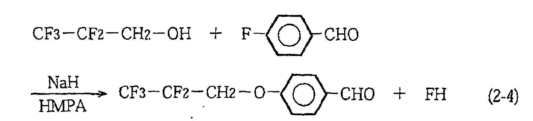
330g (1.30mol) of 4-(2,2,3,3,3-pentafluoropropyloxy) benzaldehyde,
176.7g (1.30mol) of 4-hydroxyacetophenone, 33.0g of piperidine, 33ml of
acetic acid and 3.3L of toluene were charged with the reaction flask
(internal volume: 5L) and agitated at 110°C for 5 days.
After the reaction flask was cooled down to room temperature, the
reaction solution was poured into 2.1L of 1N hydrochloric acid and the
deposited crystals were taken out by filtration.
Then, after the crystals were washed by water, they were dissolved in
15L of chloroform. Then, they were dried by using magnesium sulfate
anhydride and, thereafter, the solvent was distilled off, to obtain 322.0g of
4-(2,2,3,3,3-pentafluoropropyloxy)-4'-hydroxychalcone (GLC purity: 98%,
Yield: 66.6%).
The chemical reaction formula (2-5) in this process is given below.
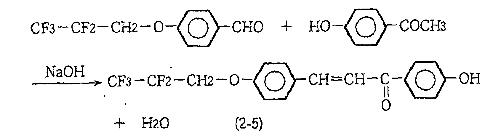
322g (0.866mol) of 4-(2,2,3,3,3-pentafluoropropyloxy)- 4'-hydroxychalcone
and 3L of dry DMF were charged with the reaction flask
(internal volume: 5L) in a stream of argon and 34.6g (0.865mol) of sodium
hydride (60%) was added thereto under freezing for 30 minutes.
Thereafter, the reaction flask was heated up to room temperature, the
reactant was agitated for 20 hours.
Then, 117.7g (0.865mol) of 6-chlorohexanol was dropped into the
mixture at the same temperature for 20 minutes and, thereafter, the
reactant was heated to 80°C to be allowed to react for 23 hours. Then,
reaction solution was poured into ice water to extract the reaction product
by using ethyl acetate. The solution was washed by water and then
magnesium sulfate was added into the ethyl acetate extracted solution for
treatment of it. Thereafter, the solvent was distilled off to obtain crude
crystals.
The crude crystals thus obtained were purified by use of silica gel
column (Moving phase: n-hexane/ethyl acetate=2/1). Further, they were
recrystallized by purifying them in silica gel column (Moving phase: n-hexane/ethyl
acetate=1/1) to obtain 123.0g of 4-(2,2,3,3,3-pentafluoropropyloxy)-4'-(6'-hydroxyhexyloxy)
chalcone (HPLC purity: 98%,
Yield: 30.1%).
The chemical reaction formula (2-6) in this process is given below.

60.0g (0.127mol) of 4-(2,2,3,3,3-pentafluoropropyloxy) -4'-(6'-hydroxyhexyloxy)
chalcone and 240.0g (1.41mol) of silicon tetrachloride
were charged with the reaction flask (internal volume: 500ml) in a stream of
argon and agitated for 1 hour at room temperature.
Surplus silicon tetrachloride was distilled off to obtain 69.4g of 4-(2,2,3,3,3-pentafluoropropyloxy)-4'-(6'-trichlorosilyloxyhexyloxy)chalcone
(Yield: 90.2%).
The chemical reaction formula (2-7) in this process is given below.
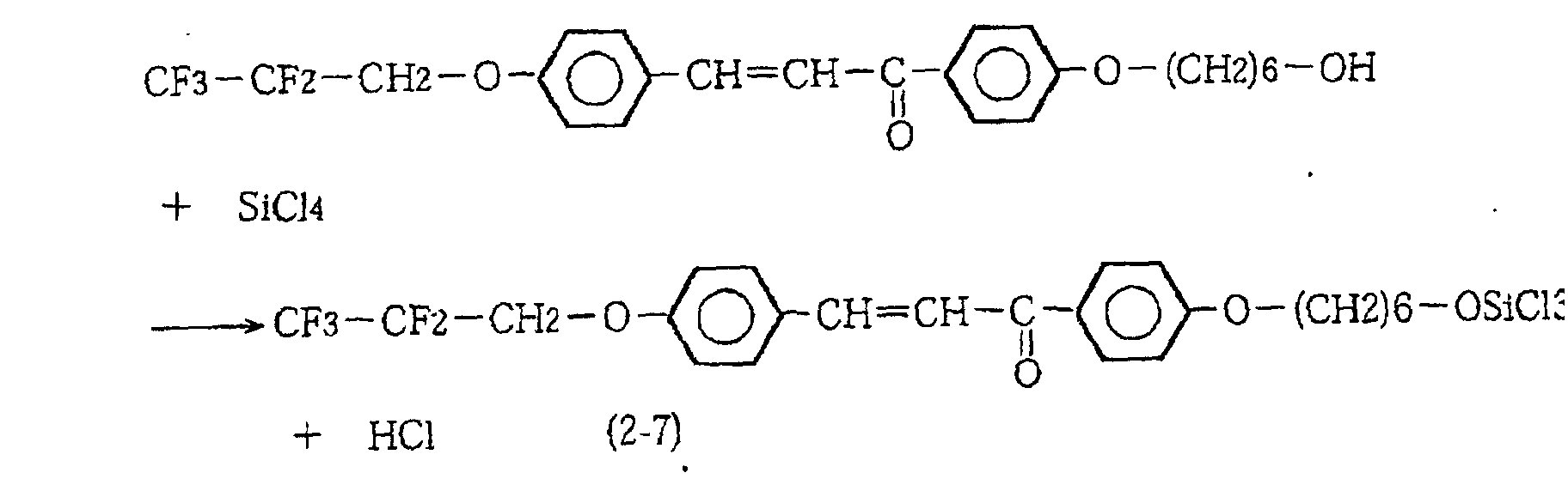
The final product was analyzed by measuring 1H-NMR spectrum.
The 1H-NMR spectrum is shown in FIG. 3. The peaks in FIG. 3 support
that the final product has the chemical structure expressed by the chemical
formula (2-7) above.
Also, the final product was dissolved in chloroform and the
ultraviolet · visible light absorption spectrum was measured. The results
are shown in FIG. 4. It was confirmed from FIG. 4 that the final product
had no absorption peaks in the visible light region, while on the other hand,
it had the absorption peaks at 327nm in the ultraviolet light region. It was
found from this that the chemical adsorption material synthesized in this
Example was low in sensitivity to visible light and high in sensitivity to
ultraviolet light.
It is to be noted that in the following Examples, R-1200 available from
Hitachi, Ltd. was used in the analysis of 1H-NMR spectrum; FT-IR 4300
available from Shimadzu Corporation was used in the analysis of IR
spectrum; and UV-240 available from Shimadzu Corporation was used in
the analysis of UV/VIS spectrum.
The method for producing the liquid crystal alignment film will be
described with reference to FIGS. 5 and 6. The surface of the glass
substrate (including a number of hydroxyl groups) forming transparent
electrodes thereon was well cleaned to remove grease to thereby finish the
glass substrate 1. On the other hand, the (silane-based) chemical
adsorption material synthesized in the above was dissolved in the mixed
solvent of the well-dehydrated siloxane solvent (Brand name: KF96L,
available from Shin-Etsu Chemical Co., Ltd.) and chloroform to a
concentration of about 1 weight%. The solution was regarded as chemical
adsorption solution 2.
Then, the glass substrate 1 was immersed in the chemical adsorption
solution 2 in a dry atmosphere of relative humidity of 30% or less for about
1 hour, as shown in FIG. 5 (Process A). Thereafter, the glass substrate 1
was immersed in and taken out from the well-dehydrated chloroform 3
(aprotic solvent) to rinse the surface of the substrate, as shown in FIG. 7
(Process B). Thereafter, the glass substrate 1 was pulled up in the
direction of an arrow 4 from the chemical adsorption solution 2 and then
was stood upright to cut the cleaning solution, so as to be dried (Process C).
Sequentially, the surface of the glass substrate 1 was exposed to the air
charged with moisture (relative humidity of 50-80%) (Process D).
The significance of the processes above is as follows. The process A in
which the glass substrate 1 is immersed in the chemical adsorption solution
2 is for a SiCl group of chlorosilane chemical adsorption material and a
hydroxyl group on the substrate to be subjected to de-HCl reaction. This
process permits the chlorosilane chemical adsorption material to be strongly
bonded to the surface of the glass substrate 1. The process B in which the
glass substrate 1 pulled up from the chemical adsorption solution 2 is
cleaned by the chloroform 3 is for removing the unreacted chemical
adsorption material from the surface of the substrate. This process is
necessary for forming the thin film of monomolecular layer form.
The cleaning solution draining and drying process after cleansing
(Process C) is for allowing the adsorbing molecules to be aligned in a fixed
direction. When the substrate is set up orienting in a fixed direction to cut
and dry the cleaning solution remaining on the thin film of the substrate,
the adsorption molecules are tentatively aligned along the draining and
drying direction. After the glass substrate 1 is pulled up from the chemical
adsorption solution after rinsing, it is set up vertically as it stands in the
direction indicated by the arrow 5 in FIG. 6.
The process D in which the substrate dried after the cleaning solution
is cut is exposed to the air charged with moisture is the de-HCl reaction
process to allow the remaining Cl of the SiCl group to react with the
moisture in the air. This process permits the siloxane bond of the
adsorption molecules.
Through these series of processes, the monomolecular film 9 is formed
which comprises chlorosilane chemical adsorption material siloxane-bonded
to the hydroxyl groups on the substrate (in a tentatively aligned state).
The monomolecular film 9 is a thin film in the monomolecular layer form
which is formed as a unit of the chemical bond given by the following
chemical formula (2-8). In place of the process for the glass substrate 1 to
be immersed in the chemical adsorption solution 2, an alternative process
may be adopted of applying the chemical adsorption solution 2 to the
surface of the glass substrate 1.

When the film thickness of the monomolecular film 9 thus produced
was measured with an ellipsometer (whose index of refraction was set at
1.45), it was about 2.5nm.
The alignment condition of the monomolecular film 9 was examined by
means of the test cell. The test cell was produced in the following manner.
Two substrates with monomolecular films 9 were produced. Then, they
were superimposed with each other with a gap of about 12 µ m in the
condition in which their respective film surfaces face inwards and their
respective film surfaces are so oriented that their solution draining
directions are opposite to each other (in the anti-parallel condition) and
then were sealed around the margins thereof. Thereafter, nematic liquid
crystal (Δ ε of about -2 and Δ n of about 0.08) was injected in the gap and
then the polarizing plates were arranged on both sides of the test cell,
respectively. Then, the orientation of liquid crystal molecules was
examined by the method that the visible light ray entering the polarizing
plate from one direction is observed at many directions. It was confirmed
from the measurement that the liquid crystal molecules were aligned along
the solution draining and drying direction.
The polarized light irradiation process will be described with reference
to FIG. 7. In FIG. 7, 5 designates the solution draining and drying
direction, 6 designates a polarized ultraviolet light, 7 designates a
polarizing direction, 8 designates transparent electrodes, and 9 designates
an aggregation of adsorption molecules (monomolecular film). The
monomolecular film 9 was subjected to the re-alignment process in the
manner as shown in FIG. 7. Specifically, after a Glan-Tayler type
polarizer was so set that the polarizing direction 6 can be oriented in the
direction generally parallel to the solution draining and drying direction 5
with respect to the monomolecular film 9, the monomolecular film 9 was
irradiated with 480mJ of a 365nm ultraviolet 8 of a 500W high-pressure
mercury lamp (2.1mW/cm2 after passing through the polarizing film).
Then, the chemical properties of the monomolecular film 9 as
irradiated with the ultraviolet rays 8 was examined by use of FT-IR
(Fourier Transform Infrared Spectroscopy). As a result of this, it was
found that there was difference in IR absorption between the polarizing
direction and the direction orthogonal thereto. Specifically, it was found
that the IR absorption was significantly reduced in the polarizing direction,
rather than in the direction orthogonal to the polarizing direction. The
reduction of the IR absorption means that the chalcone skeleton was cross-linked
at its carbon-carbon double bond portion by the optical energy in the
polarizing direction. Hence, it was confirmed from this result that the
irradiation of the polarized ultraviolet light enables the cross-link.
Though the direction for the molecules to be bonded to each other was
not clarified by the FT-IR analysis, it is apparent that when the adsorption
molecules are cross-linked to each other, the relation between the
adsorption molecules is sterically stabilized. Consequently, the
monomolecular film after the re-alignment process (liquid crystal alignment
film) is probably more stable in alignment of liquid crystals than in the
tentatively aligned state.
Also, the liquid crystal cell was produced in the same manner as in the
above-mentioned test cell by use of the substrate with the liquid crystal
alignment film as was re-aligned. Then, it was put to the liquid crystal
alignment test. The result was that when no voltage was applied to the
liquid crystal cell, the light was hindered from transmitting through the cell
to thereby produce the black display, while on the other hand, when the
voltage of 3 volts was applied thereto, the light was permitted to transmit
therethrough to thereby produce the white display. This means that the
alignment of the liquid crystal molecules was converted into the
homogeneous alignment from the homeotropic alignment through the
application of voltage. Further, when the pretilt angle was measured by
the magnetic field threshold method, it was confirmed that the liquid
crystal molecules were aligned at the pretilt angle of about 89.5 degree.
It was confirmed from these results that when the aggregation of
adsorption molecules having the chemical bond units expressed by the
chemical formula (1-8) above was subjected to the re-alignment process
involving the cross link, in addition to the tentative alignment process, a
ultrathin liquid crystal alignment film that can provide the high contrast
ratio display by switching the voltage to ON and OFF was realized. It was
also confirmed that in this liquid crystal alignment film, the adsorption
molecules were cross-linked to each other. Consequently, the alignment
characteristic is hard to deteriorate.
In Example 2-2, the substrate on which the pixel electrodes were
arrayed in a matrix form was used, and the liquid crystal alignment film
was formed on the substrate in the same manner as in Example 2-1. This
substrate with the liquid crystal alignment film was used to produce a
liquid crystal display. In the following, the producing process of the liquid
crystal display of Example 2-2 will be described with reference to FIG. 8.
The chemical adsorption solutions which were prepared in the same
manner as in Example 2-1 were made to contact with (i) a first substrate 23
having thereon a first group of transparent electrodes 21 arranged in a
matrix form and a group of transistors 22 to drive the first group of
electrodes and (ii) a second substrate 26 having thereon a group of color
filters 24 and a second group of transparent electrodes 25 (common
electrodes), respectively. Further, they are subjected to a series of
processes of the solution draining and drying process and the polarized
irradiation process to thereby produce the substrates 23, 26 with liquid
crystal alignment films.
When the alignment properties of the alignment films of the
substrates 23, 26 with liquid crystal alignment films were examined in the
same manner as in Example 2-1, it was found that the liquid crystal
alignment film 27 in which the liquid crystals were re-aligned along the
electrode pattern was produced. Then, the substrates 23, 26 with liquid
crystal alignment films were adapted to render the alignment of the liquid
crystal alignment film homeotropic. Then, they were superimposed with
each other, with a cell gap of 4.5 µ m formed between the substrates by
spacer 28 and adhesive 29, to thereby produce the liquid crystal cell.
Sequentially, nematic liquid crystal (Δ ε of about -3 and Δ n of about
0.09) 30 was injected in the cell gap and the cell was fully sealed.
Thereafter, the polarizing plates 31, 32 were combined with the cell to
complete the liquid crystal display.
When the pretilt angle of the liquid crystal molecules in the liquid
crystal display was measured by the magnetic field threshold method, it
was about 89.8 degree. When the liquid crystal display was driven by
video signals, while the liquid crystal display was irradiated with backlight
33 from the back thereof, it was confirmed that it could display a clear
picture with respect to the direction of arrow A.
The liquid crystal alignment film was formed on the substrate in the
same manner as in Example 2-2, except that the chemical adsorption
material used was a mixed solution formed by phenyltrichlorosilane and
fluorochemical adsorption material used in Example 1 (4-(2,2,3,3,3,-Pentafluoropropyloxy)-4'-(6'-trichlorosilyloxyhexyloxy)chalcone)
being
mixed at a mixing ratio of 9:1.
The liquid crystal alignment film thus produced was measured on the
pretilt angle of the liquid crystal molecules by the crystal rotation method.
The result was that the pretilt angle was 8.5 degree.
Further, the liquid crystal display was produced in the same manner
as in Example 2-2. The liquid crystal material used was nematic liquid
crystal whose Δ ε was about 2.3 and Δn was about 0.26. Further, when
the liquid crystal display was driven by use of video signals, while the liquid
crystal display was irradiated with backlight from the back thereof, it was
confirmed that it could display a clear picture.
It was confirmed from this fact that the liquid crystal alignment film
having good controllability of alignment of liquid crystals and having the
capabilities of controlling the liquid crystals at a desired pretilt angle and
displaying clear picture could be provided by mixing the two different
chemical adsorption materials.
In the irradiation of polarized ultraviolet light after the tentative
alignment, a pattern-like mask for dividing each picture element into four
regions in a checkered pattern was laid over the polarizing plate and then
was exposed to light at one time, to thereby produce a multi-domain type
liquid crystal alignment film having four divided regions different in
orientation for the liquid crystals to be aligned in patterns within the same
picture element. Except this condition, the multi-domain type liquid
crystal display according to Example 2-4 was produced in the same
conditions as in Example 2-2.
When the liquid crystal display was driven by use of video signals in
the same manner as in Example 2-2, it was confirmed that it could display a
picture of a wide viewing angle, as compared with the case of Example 2-2.
The two comb electrodes meshed with each other in a non-contact
state were disposed on the same plane of a single substrate and then the
liquid crystal alignment film as was subjected to the re-alignment process
was further formed on those electrodes in the same manner as in Example 1.
However, the chemical adsorption solution used was a mixed solution
formed by fluorochemical adsorption material synthesized in Example 1 (4-(2,2,3,3,3,-Pentafluoropropyloxy)-4'-(6'-trichlorosilyloxyhexyloxy)chalcone)
and the chemical adsorption material in which the fluorine was not
contained in the fluorochemical adsorption material synthesized in
Example 1 being mixed at a mixing ratio of 1:29. The opposite substrate
was superimposed with the substrate with the liquid crystal alignment film
to form the liquid crystal cell in the usual way to thereby produce an in-plane
switching (IPS) mode of liquid crystal display.
In the liquid crystal display also, the picture display test was
conducted by using video signals in the same manner as in Example 2-2 or
Example 2-4. It was confirmed from this test that the picture was
displayed with an expanded viewing angle.
To achieve the control of the liquid crystal alignment capabilities of
the liquid crystal alignment film, one is not limited to using the annealing
process mentioned above. One can use another process that additional
chemical adsorption material having a different affinity to the liquid crystal
from the chemical adsorption material synthesized in Example 2-1 is added
and a mixing ratio between the both is varied variously. Further, one can
use still another process that kinds of cleaning solutions used in the process
for cleansing the substrate to which the chemical adsorption material is
adsorbed (corresponding to the process B in Example 2-1) are varied.
It is to be understood that the specific embodiments described above
are only for clarifying the technical contents of the present invention and
the present invention should not be construed in such a narrow sense that it
is limited to such concrete examples and that various changes and
modifications may be made in the invention without departing from the
sprit thereof and the scope of the following claims.
As described above, according to the construction of the present
invention, the objects of the present invention can fully be achieved.
According to the first group of invention, the novel chemical
adsorption material of the invention comprises a functional group having at
one end thereof a functional group of very small critical surface tension and
at the other end thereof a functional group capable of strong chemical bond
to a hydrophilic group on the surface of the substrate, and a photosensitive
group. Consequently, according to the present invention, a thin film of a
monomolecular layer form can be formed on the surface of the base
substance with ease. The thin film is stable and transparent in the visible
light region and also excellent in water repellency and durability, so that it
is useful as a functional coating film for modification of surface property.
Further, the chemical adsorption material of the present invention can
allow the adsorption molecules to be cross-linked to each other in a specific
direction by the process that the chemical adsorption material is chemically
adsorbed to the surface of the base substance and thereafter is irradiated
with polarized ultraviolet light. This can produce the liquid crystal
alignment film having strong and stable alignment properties.
In addition, according to the producing method of chemical adsorption
material of the present invention, the chemical adsorption material
mentioned above can be produced with efficiency.
From the foregoing, according to the present invention, there is
provided the novel thin-film forming chemical adsorption material that is
useful as a surface property modifying agent for a base substance, or
particularly useful as the material of the liquid crystal alignment film.
Consequently, industrial significance of the present invention is great.
According to the second group of the invention, there is provided the
liquid crystal alignment film of far small in thickness and uniform in
alignment, as compared with the conventional organic polymer liquid
crystal alignment film. Also, since the liquid crystal alignment film has
the structure in which the adsorption molecules are strongly bonded and
anchored on the surfaces of electrodes via the chemical adsorption and also
are cross-linked to each other, it is excellent in adhesion to the substrate
and also is resistant to deterioration of the alignment properties resulting
from external factors such as heat and friction. Further, there exists a
perfluoromethyl group at an end of the adsorption molecule on the front side
of the film, and as such can produce the liquid crystal alignment film having
a very large critical surface tension and can allow the liquid crystal
molecules to be aligned to a high pretilt angle. Furthermore, since
individual adsorption molecules are contributive to the control of alignment
of liquid crystal molecules, far excellent alignment properties can be
provided.
Further, the thin film of a monomolecular layer form comprising the
aggregation of adsorption molecules has significantly advantageous
properties as the liquid crystal alignment film that it does not hinder the
transmission of light due to its excellent transmission of the visible light
and that it does not hinder the electric field to drive the liquid crystals due
to its small electrical resistance.
According to the producing method of the present invention, the
multi-domain type liquid crystal alignment film of different in orientation
for the liquid crystals to be aligned in each of the regions divided to a
pattern can be reliably and efficiently produced by a relatively simple
technique simply using the solution draining and drying process and the
irradiation of polarized light. The applications of the liquid crystal
alignment film according to the present invention can provide the
homeotropic alignment mode of multi-domain type liquid crystal display
having wide viewing angle, high picture quality, high contrast and excellent
high-speed response with little increase of costs.
Claims (57)
- A thin film forming chemical adsorption material comprising at least a functional group expressed by the following chemical formula (1-1) and a-SiX group (X represents halogen) as an end group bonded by siloxane bond:

- The thin film forming chemical adsorption material according to Claim 1, wherein the chemical adsorption material is expressed by the following chemical formula (1-2):

- A producing method of a thin film forming chemical adsorption material comprising at least:the chemical reaction process 1 that at least 4-(2,2,3,3,3-Pentafluoropropyloxy) benzaldehyde and 4-hydroxyacetophenone are subjected to aldol condensation reaction to synthesize alcohol having a chalcone skeleton expressed by the following chemical formula (1-3) (chemical reaction process 1); andthe chemical reaction process 2 that after the chemical reaction process 1, SiX4 (X represents halogen) is subjected to dehydrohalogenation reaction with alcohol having the chalcone skeleton under an inert gas atmosphere, to synthesize chemical adsorption material having a characteristic group expressed by the following chemical formula (1-1) and a -O-SiX3 group:


- The producing method of a thin film forming chemical adsorption material according to Claim 3, wherein the chemical adsorption material is a compound expressed by the following chemical formula (1-2):

- An organic thin film comprising an aggregation of adsorption molecules directly bonded and anchored to or indirectly bonded and anchored to a surface of a base substance through another material layer via chemical adsorption, wherein the aggregation of adsorption molecules include adsorption molecule having a characteristic group expressed by the following chemical formula (2-1) and a -O-Si bond group at a molecular end group:

- The organic thin film according to Claim 5, wherein the adsorption molecule having the characteristic group expressed by the chemical formula (2-1) and the -O-Si bond group at the molecular end group is a compound expressed by the following chemical formula (2-2):

- The organic thin film according to Claim 5, wherein the aggregation of adsorption molecules forming the organic thin film are aligned in a given direction.
- The organic thin film according to Claim 5, wherein the aggregation of adsorption molecules forming the organic thin film are adsorbed on a substrate in such a manner that the adsorption molecules in adjoining divided regions are differentiated from each other in tilt of their major exes with respect to the surface of the substrate and/or in orientation of alignment thereof, and wherein the divided regions are formed by dividing a single picture element into a number of regions in a pattern-like form.
- The organic thin film according to Claim 5, wherein the aggregation of adsorption molecules forming the organic thin film are cross-linked to each other via a boning line(s) of C' and/or C" in the chemical formula (2-1) or (2-2).
- The organic thin film according to Claim 9, which has film thickness of 0.5nm or more to less than 10nm.
- The organic thin film according to Claim 9, which a thin film of a monomolecular layer form.
- The organic thin film according to Claim 5, wherein the organic thin film comprises an aggregation of adsorption molecules of various kinds
- A producing method of an organic thin film comprising an aggregation of adsorption molecules directly bonded and anchored to or indirectly bonded and anchored to a surface of a base substance through another material layer via chemical adsorption, the producing method comprising:
the process that chemical adsorption material having a characteristic group expressed by the following chemical formula (2-1) and a -O-Si bond group at a molecular end portion thereof is at least dissolved in non-water-borne solvent, to prepare chemical adsorption solution:the process that the chemical adsorption solution is put into contact with the surface of the base substance, so that the chemical adsorption material in the chemical adsorption solution is chemically adsorbed on the surface of the base substrate; andthe solution draining and drying process that the surface of the base substance to which the chemical adsorption material was bonded is cleaned by use of the non-water-borne solvent and, thereafter, the base substance is stood up in a specific direction to cut and dry the cleaning solution:
- The producing method of an organic thin film according to Claim 13, which further comprises the polarized ultraviolet irradiation process that after the solution draining and drying process, the adsorption molecules on the surface of the base substance are irradiated with polarized ultraviolet light, so that they are cross-linked to each other via a bonding line of a carbon-carbon double bond portion of the chemical formula (2-1).
- The producing method of an organic thin film according to Claim 14, wherein a series of alignment film treatment processes comprising the solution draining and the drying process and a polarized ultraviolet irradiation process are repeated a number of times in such a manner that the solution draining and drying process returns back again from the polarized ultraviolet irradiation process, and each time when repeated, the solution draining and drying direction is varied and that the polarized ultraviolet light irradiation region and polarized ultraviolet light irradiation direction, or the polarized ultraviolet light irradiation region and polarized ultraviolet light irradiation angle, or the polarized ultraviolet light irradiation region, polarized ultraviolet light irradiation direction and polarized ultraviolet light irradiation angle, are varied, whereby the adsorption molecules are varied in tilt of their major exes with respect to the surface of the base substance and/or in orientation of alignment thereof from one divided region to another of a number of divided regions into which a region corresponding to one picture element is divided in a pattern-like form.
- The producing method of an organic thin film according to Claim 13, wherein aprotic solvent is used as the non-water-borne solvent for use in cleaning, so that unreacted chemical adsorption material is cleaned and removed from the surface of the base substance by use of the aprotic solvent, to produce a thin film of a monomolecular layer form.
- The producing method of an organic thin film according to Claim 13, wherein a mixed solvent of aprotic solvent and protic solvent is used as the non-water-borne solvent for use in cleaning, so that unreacted chemical adsorption material is cleaned and removed from the surface of the base substance by use of the mixed solvent, to produce a thin film of a monomolecular layer form.

- The producing method of an organic thin film according to Claim 13, wherein the chemical adsorption material having a characteristic group expressed by the chemical formula (2-1) and a -O-Si bond group at a molecular end portion thereof is a compound expressed by the following chemical formula (2-2).
- A liquid crystal alignment film comprising an aggregation of adsorption molecules bonded and anchored directly on a surface of a substrate forming electrodes thereon or indirectly bonded and anchored thereon through another material layer, wherein the aggregation of adsorption molecules include adsorption molecule having a characteristic group expressed by the following chemical formula (2-1) and a -O-Si bond group at a molecular end group:

- The liquid crystal alignment film according to Claim 19, wherein the adsorption molecule having the characteristic group expressed by the chemical formula (2-1) and the -O-Si bond group at the molecular end group is a compound expressed by the following chemical formula (2-2):

- The liquid crystal alignment film according to Claim 19, wherein the aggregation of adsorption molecules forming the liquid crystal alignment film are aligned in a given direction.
- The liquid crystal alignment film according to Claim 19, wherein the aggregation of adsorption molecules forming the liquid crystal alignment film are adsorbed on a substrate in such a manner that the adsorption molecules in adjoining divided regions are differentiated from each other in tilt of their major exes with respect to the surface of the substrate and/or in orientation of alignment thereof, and wherein the divided regions are formed by dividing a single picture element into a number of regions in a pattern-like form.
- The liquid crystal alignment film according to Claim 19, wherein the adsorption molecules forming the liquid crystal alignment film are cross-linked to each other via a boning line(s) of C' and/or C" in the chemical formula (2-1) or (2-2).
- The liquid crystal alignment film according to Claim 23, which has film thickness of 0.5nm or more to less than 10nm.
- The liquid crystal alignment film according to Claim 23, which is a thin film of a monomolecular layer form.
- The liquid crystal alignment film according to Claim 19, which is an alignment film that develops a desired pretilt angle for the liquid crystal molecules.
- The liquid crystal alignment film according to Claim 26, wherein the liquid crystal alignment film comprises the aggregation of adsorption molecules of various kinds, and the liquid crystal molecules are aligned at a desired pretilt angle by changing a constituent ratio between the various kinds of adsorption molecules
- A producing method of a liquid crystal alignment film comprising an aggregation of adsorption molecules directly bonded and anchored to or indirectly bonded and anchored to a surface of a substrate forming thereon electrodes through another material layer via chemical adsorption, the producing method comprising:
the process that chemical adsorption material having a characteristic group expressed by the following chemical formula (2-1) and a -O-Si bond group at a molecular end portion thereof is at least dissolved in non-water-borne solvent, to prepare chemical adsorption solution:the process that the chemical adsorption solution is put into contact with the surface of the substrate forming the electrodes thereon, so that the chemical adsorption material in the chemical adsorption solution is chemically adsorbed on the surface of the substrate; andthe solution draining and drying process that the surface of the substrate to which the chemical adsorption material was bonded is cleaned by use of the non-water-borne cleaning solvent and, thereafter, the substrate is stood up in a specific direction to cut and dry the cleaning solution:
- The producing method of the liquid crystal alignment film according to Claim 28, which further comprises the polarized ultraviolet irradiation process that after the solution draining and drying process, the adsorption molecules on the surface of the substrate are irradiated with polarized ultraviolet light, so that they are cross-linked to each other via a bonding line of a carbon-carbon double bond portion of the chemical formula (2-1).
- The producing method of the liquid crystal alignment film according to Claim 28, wherein a series of alignment film treatment processes comprising the solution draining and the drying process and a polarized ultraviolet irradiation process are repeated a number of times in such a manner that the solution draining and drying process returns back again from the polarized ultraviolet irradiation process, and each time when repeated, the solution draining and drying direction is varied and that the polarized ultraviolet light irradiation region and polarized ultraviolet light irradiation direction, or the polarized ultraviolet light irradiation region and polarized ultraviolet light irradiation angle, or the polarized ultraviolet light irradiation region, polarized ultraviolet light irradiation direction and polarized ultraviolet light irradiation angle, are varied, whereby the adsorption molecules are varied in tilt of their major exes with respect to the surface of the substrate and/or in orientation of alignment thereof from one divided region to another of a number of divided regions into which a region corresponding to one picture element is divided in a pattern-like form.
- The producing method of the liquid crystal alignment film according to Claim 28, wherein aprotic solvent is used as the non-water-borne solvent for use in cleaning, so that unreacted chemical adsorption material is cleaned and removed from the surface of the substrate by use of the aprotic solvent, to produce a thin film of a monomolecular layer form.
- The producing method of the liquid crystal alignment film according to Claim 28, wherein a mixed solvent of aprotic solvent and protic solvent is used as the non-water-borne solvent for use in cleaning, so that unreacted chemical adsorption material is cleaned and removed from the surface of the substrate by use of the mixed solvent, to produce a thin film of a monomolecular layer form.
- The producing method of the liquid crystal alignment film according to Claim 28, wherein the chemical adsorption material having a characteristic group expressed by the chemical formula (2-1) and a -O-Si bond group at a molecular end portion thereof is a compound expressed by the following chemical formula (2-2).

- A liquid crystal display comprising:a pair of opposed substrates;a liquid crystal alignment film formed at least on a surface of a substrate having electrodes of the pair of substrates; andliquid crystals accommodated in a cell gap between the pair of opposed substrates,wherein the liquid crystal alignment film comprises an aggregation of adsorption molecules bonded and anchored directly on a surface of the substrate forming the electrodes thereon or indirectly bonded and anchored thereon through another material layer via chemical adsorption, and wherein the aggregation of adsorption molecules include adsorption molecule having a characteristic group expressed by the following chemical formula (2-1) and a -O-Si bond group at a molecular end group:

- The liquid crystal display according to Claim 34, wherein the adsorption molecule having the characteristic group expressed by the chemical formula (2-1) and the -O-Si bond group at the molecular end group is a compound expressed by the following chemical formula (2-2):

- The liquid crystal display according to Claim 34, wherein a pretilt angle and/or a pretilt orientation of the adsorption molecules accommodated in the cell gap are controlled by tilt and/or orientation of alignment of the adsorption molecules' major axes with respect to surface of the substrate.
- The liquid crystal display according to Claim 34, wherein the adsorption molecules are differentiated from each other in tilt and/or orientation of alignment of their major axes with respect to surface of the substrate from one divided region to another of adjoining divided regions into which a single picture element is divided in a pattern-like form.
- The liquid crystal display according to Claim 34, wherein the adsorption molecules forming the liquid crystal alignment film are cross-linked to each other via a boning line(s) of C' and/or C" in the chemical formula (2-1) or (2-2).
- The liquid crystal display according to Claim 34, wherein the liquid crystal alignment film has film thickness of 0.5nm or more to less than 10nm.
- The liquid crystal display according to Claim 34, wherein the liquid crystal alignment film is a thin film of a monomolecular layer form.
- The liquid crystal display according to Claim 34, wherein the liquid crystal alignment film is an alignment film that develops a desired pretilt angle for the liquid crystal molecules.
- The liquid crystal display according to Claim 41, wherein the liquid crystal alignment film comprises the aggregation of adsorption molecules of various kinds, and the liquid crystal molecules are aligned at a desired pretilt angle by changing a constituent ratio between the various kinds of adsorption molecules
- The liquid crystal display according to Claim 42, whose display mode is a display mode selected from the group consisting of TN (Twisted Nematic) mode, STN (Super Twisted Nematic) mode, OCB (Optically Self-Compensated Birefringence) mode and VA (Vertical Alignment) mode.
- An in-plane switching type liquid crystal display comprising pixel electrodes and opposed electrodes, which are arranged on a substrate, and a liquid crystal alignment film formed on a surface of the substrate on which the electrodes are arranged, wherein the liquid crystal alignment film comprises an aggregation of adsorption molecules bonded and anchored directly on a surface of the substrate forming the electrodes thereon or indirectly bonded and anchored thereon through another material layer via chemical adsorption, and wherein the aggregation of adsorption molecules include adsorption molecule having a characteristic group expressed by the following chemical formula (2-1) and a -O-Si bond group at a molecular end group:

- The liquid crystal display according to Claim 44, wherein the adsorption molecule having the characteristic group expressed by the chemical formula (2-1) and the -O-Si bond group at the molecular end group is a compound expressed by the following chemical formula (2-2):

- The liquid crystal display according to Claim 44, wherein a pretilt angle and/or a pretilt orientation of the adsorption molecules accommodated in the cell gap are controlled by tilt and/or orientation of alignment of the adsorption molecules' major axes with respect to surface of the substrate.
- The liquid crystal display according to Claim 44, wherein the adsorption molecules forming the liquid crystal alignment film are cross-linked to each other via a boning line(s) of C' and/or C" in the chemical formula (2-1) or (2-2).
- The liquid crystal display according to Claim 44, wherein the liquid crystal alignment film has film thickness of 0.5nm or more to less than 10nm.
- The liquid crystal display according to Claim 44, wherein the liquid crystal alignment film is a thin film of a monomolecular layer form.
- The liquid crystal display according to Claim 44, wherein the liquid crystal alignment film comprises the aggregation of adsorption molecules of various kinds.
- The liquid crystal display according to Claim 50, wherein the liquid crystal alignment film is an alignment film that controls its liquid crystal alignment capabilities in such a manner that the liquid crystal molecules are aligned at a desired pretilt angle by changing a proportion of various kinds of adsorption molecules.
- A producing method of a liquid crystal display having a liquid crystal alignment film comprising an aggregation of adsorption molecules directly bonded and anchored to or indirectly bonded and anchored to a surface of a substrate forming thereon electrodes through another material layer via chemical adsorption, the producing method comprising:
the process that chemical adsorption material having a characteristic group expressed by the following chemical formula (2-1) and a -O-Si bond group at a molecular end portion thereof is dissolved in non-water-borne solvent, to prepare chemical adsorption solution:the process that the chemical adsorption solution is put into contact with the surface of the substrate forming the electrodes thereon, so that the chemical adsorption material in the chemical adsorption solution is chemically adsorbed on the surface of the substrate; andthe solution draining and drying process that the surface of the substrate to which the chemical adsorption material was bonded is cleaned by use of the non-water-borne cleaning solvent and, thereafter, the substrate is stood up in a specific direction to cut and dry the cleaning solution:
- The producing method of the liquid crystal display according to Claim 52, which further comprises the polarized ultraviolet irradiation process that after the solution draining and drying process, the adsorption molecules on the surface of the substrate are irradiated with polarized ultraviolet light, so that they are cross-linked to each other via a bonding line of a carbon-carbon double bond portion of the chemical formula (2-1).
- The producing method of the liquid crystal display according to Claim 52, wherein a series of alignment film treatment processes comprising the solution draining and the drying process and the polarized ultraviolet irradiation process are repeated a number of times in such a manner that the solution draining and drying process returns back again from the polarized ultraviolet irradiation process, and each time when repeated, the solution draining and drying direction is varied and that the polarized ultraviolet light irradiation region and polarized ultraviolet light irradiation direction, or the polarized ultraviolet light irradiation region and polarized ultraviolet light irradiation angle, or the polarized ultraviolet light irradiation region, polarized ultraviolet light irradiation direction and polarized ultraviolet light irradiation angle, are varied, whereby the adsorption molecules are varied in tilt of their major exes with respect to the surface of the substrate and/or in orientation of alignment thereof from one divided region to another of a number of divided regions into which a region corresponding to one picture element is divided in a pattern-like form.
- The producing method of the liquid crystal display according to Claim 52, wherein aprotic solvent is used as the non-water-borne solvent for use in cleaning, so that unreacted chemical adsorption material is cleaned and removed from the surface of the substrate by use of the aprotic solvent, to produce a thin film of a monomolecular layer form.
- The producing method of the liquid crystal display according to Claim 52, wherein a mixed solvent of aprotic solvent and protic solvent is used as the non-water-borne solvent for use in cleaning, so that unreacted chemical adsorption material is cleaned and removed from the surface of the substrate by use of the mixed solvent, to produce a thin film of a monomolecular layer form.
- The producing method of the liquid crystal display according to Claim 52, wherein the chemical adsorption material having a characteristic group expressed by the chemical formula (2-1) and a -O-Si bond group at a molecular end portion thereof is a compound expressed by the following chemical formula (2-2).

Applications Claiming Priority (5)
| Application Number | Priority Date | Filing Date | Title |
|---|---|---|---|
| JP19043799 | 1999-07-05 | ||
| JP19038599 | 1999-07-05 | ||
| JP19043799 | 1999-07-05 | ||
| JP11190385A JP2001021897A (en) | 1999-07-05 | 1999-07-05 | Chemisorbent for thin film formation and method for producing the same |
| PCT/JP2000/004505 WO2001002510A1 (en) | 1999-07-05 | 2000-07-05 | Chemically adsorbable substance for forming thin film, and method for producing the same and use of the same |
Publications (2)
| Publication Number | Publication Date |
|---|---|
| EP1130072A1 true EP1130072A1 (en) | 2001-09-05 |
| EP1130072A4 EP1130072A4 (en) | 2007-10-24 |
Family
ID=26506052
Family Applications (1)
| Application Number | Title | Priority Date | Filing Date |
|---|---|---|---|
| EP00944298A Withdrawn EP1130072A4 (en) | 1999-07-05 | 2000-07-05 | CHEMICALLY ABSORBABLE SUBSTANCE FOR THE MANUFACTURE OF THIN FILMS AND METHOD FOR THE PRODUCTION THEREOF. |
Country Status (6)
| Country | Link |
|---|---|
| US (1) | US6524715B1 (en) |
| EP (1) | EP1130072A4 (en) |
| KR (1) | KR100430120B1 (en) |
| CN (1) | CN1179015C (en) |
| TW (1) | TW483929B (en) |
| WO (1) | WO2001002510A1 (en) |
Cited By (1)
| Publication number | Priority date | Publication date | Assignee | Title |
|---|---|---|---|---|
| US7074344B2 (en) * | 2001-10-03 | 2006-07-11 | Jsr Corporation | Liquid crystal aligning agent and liquid crystal display element |
Families Citing this family (6)
| Publication number | Priority date | Publication date | Assignee | Title |
|---|---|---|---|---|
| KR100601454B1 (en) * | 2000-10-04 | 2006-07-14 | 엘지.필립스 엘시디 주식회사 | Multi-domain liquid crystal display and manufacturing method |
| KR100487959B1 (en) * | 2001-09-27 | 2005-05-04 | 재단법인서울대학교산학협력재단 | Chalcone Compounds for Photoimaging and Photomemory and Method of Preparing the Same |
| US7700000B2 (en) * | 2005-11-23 | 2010-04-20 | Lg Chem, Ltd. | Silicon derivative, liquid crystal composition comprising the same and compensation film using the same liquid crystal composition |
| CN102472934A (en) * | 2009-07-28 | 2012-05-23 | 夏普株式会社 | Liquid crystal display element |
| CN116560142A (en) * | 2023-03-13 | 2023-08-08 | 成都瑞波科材料科技有限公司 | Liquid crystal alignment film, preparation method of alignment film and liquid crystal display panel |
| CN116651383B (en) * | 2023-04-21 | 2024-04-05 | 海南大学 | A large-channel thick-film hydrogel material and a device for extracting uranium from seawater for engineering purposes |
Family Cites Families (10)
| Publication number | Priority date | Publication date | Assignee | Title |
|---|---|---|---|---|
| JP2558903B2 (en) | 1989-03-09 | 1996-11-27 | 松下電器産業株式会社 | Liquid crystal alignment film, manufacturing method thereof, and liquid crystal display device using the same |
| DE69221102T2 (en) | 1991-12-20 | 1998-01-08 | Fujitsu Ltd | Liquid crystal display device with different divided orientation areas |
| JP3308356B2 (en) | 1993-09-03 | 2002-07-29 | 旭硝子株式会社 | Substrate with alignment film for liquid crystal element, method for manufacturing the same, and liquid crystal element |
| JP3075917B2 (en) | 1994-05-27 | 2000-08-14 | シャープ株式会社 | Liquid crystal display device, its manufacturing method and its manufacturing device |
| KR100376368B1 (en) * | 1997-07-31 | 2003-03-15 | 마츠시타 덴끼 산교 가부시키가이샤 | Chemisorptive substance and processes for producing these |
| JPH11125822A (en) | 1997-10-23 | 1999-05-11 | Matsushita Electric Ind Co Ltd | Chemically adsorbed substance for liquid crystal alignment film and method for producing the same |
| DE69831354T2 (en) * | 1997-11-18 | 2006-06-29 | Matsushita Electric Industrial Co., Ltd., Kadoma | METHOD FOR THE PRODUCTION OF LIQUID CRYSTAL DISPLAYS USING A CHEMISORPTION FILM |
| JP3302645B2 (en) * | 1998-08-04 | 2002-07-15 | 松下電器産業株式会社 | Liquid crystal alignment film and liquid crystal display device using the same |
| JP3540167B2 (en) * | 1998-08-05 | 2004-07-07 | 松下電器産業株式会社 | Chemisorbed substance and method for producing the same |
| TW482932B (en) | 1999-07-05 | 2002-04-11 | Matsushita Electric Industrial Co Ltd | Chemical adsorbate compound, organic film, liquid crystal alignment film, and liquid crystal display device utilizing the chemical adsorbate compound |
-
2000
- 2000-07-05 CN CNB008018634A patent/CN1179015C/en not_active Expired - Lifetime
- 2000-07-05 TW TW089113327A patent/TW483929B/en not_active IP Right Cessation
- 2000-07-05 EP EP00944298A patent/EP1130072A4/en not_active Withdrawn
- 2000-07-05 US US09/786,158 patent/US6524715B1/en not_active Expired - Lifetime
- 2000-07-05 WO PCT/JP2000/004505 patent/WO2001002510A1/en not_active Ceased
- 2000-07-05 KR KR10-2001-7002314A patent/KR100430120B1/en not_active Expired - Lifetime
Cited By (1)
| Publication number | Priority date | Publication date | Assignee | Title |
|---|---|---|---|---|
| US7074344B2 (en) * | 2001-10-03 | 2006-07-11 | Jsr Corporation | Liquid crystal aligning agent and liquid crystal display element |
Also Published As
| Publication number | Publication date |
|---|---|
| KR100430120B1 (en) | 2004-05-03 |
| WO2001002510A8 (en) | 2001-03-01 |
| CN1179015C (en) | 2004-12-08 |
| TW483929B (en) | 2002-04-21 |
| WO2001002510A1 (en) | 2001-01-11 |
| US6524715B1 (en) | 2003-02-25 |
| EP1130072A4 (en) | 2007-10-24 |
| KR20010072900A (en) | 2001-07-31 |
| CN1321183A (en) | 2001-11-07 |
Similar Documents
| Publication | Publication Date | Title |
|---|---|---|
| KR0179115B1 (en) | Liquid crystal alignment photosensitive material and liquid crystal display device using the same | |
| JPH10324690A (en) | Photocrosslinkable silane derivative | |
| US20140009732A1 (en) | Liquid crystal display and method of manufacturing the same | |
| KR19990021992A (en) | Liquid crystal alignment film | |
| KR100376368B1 (en) | Chemisorptive substance and processes for producing these | |
| JP2000515923A (en) | Liquid crystal composition and alignment layer | |
| WO2009133803A1 (en) | Liquid crystal aligning agent and method for forming liquid crystal alignment films | |
| WO2000055151A1 (en) | Photoactive pentaerythritol derivatives and orientation layers | |
| US6524715B1 (en) | Thin-film forming chemical adsorption material, producing method thereof and applications thereof | |
| US6610462B1 (en) | Liquid crystal alignment using photo-crosslinkable low molecular weight materials | |
| US6451392B1 (en) | Chemical adsorbate compound, organic film, liquid crystal alignment film, and liquid crystal display device utilizing the chemical adsorbate compound | |
| JPH10153783A (en) | Liquid crystal alignment film, method of manufacturing the same, liquid crystal display device using the same, and method of manufacturing the same | |
| JP2000080164A (en) | Polyimide precursor, polyimide and alignment agent for liquid crystal cell | |
| JP4355406B2 (en) | Optical compensation sheet manufacturing method | |
| JP3537709B2 (en) | Liquid crystal alignment film and liquid crystal display device using the same | |
| JP3302645B2 (en) | Liquid crystal alignment film and liquid crystal display device using the same | |
| JP3497119B2 (en) | Organic thin film and manufacturing method thereof, liquid crystal alignment film and manufacturing method thereof, and liquid crystal display device and manufacturing method thereof | |
| JP3537713B2 (en) | Liquid crystal alignment film and liquid crystal display device using the same | |
| JPH11149077A (en) | Method for manufacturing liquid crystal alignment film and method for manufacturing liquid crystal display device using the same | |
| KR100241925B1 (en) | Photosensitive polymer liquid crystal aligning agent | |
| JPH11125821A (en) | Liquid crystal alignment film, method of manufacturing the same, liquid crystal display device using the same, and method of manufacturing the same | |
| JP2001021897A (en) | Chemisorbent for thin film formation and method for producing the same | |
| JPH04242225A (en) | Method for producing polyamic acid thin film and liquid crystal display device using the polyamic acid thin film | |
| MXPA99000938A (en) | Liquid crystal composition and alignment layer |
Legal Events
| Date | Code | Title | Description |
|---|---|---|---|
| PUAI | Public reference made under article 153(3) epc to a published international application that has entered the european phase |
Free format text: ORIGINAL CODE: 0009012 |
|
| 17P | Request for examination filed |
Effective date: 20010323 |
|
| AK | Designated contracting states |
Kind code of ref document: A1 Designated state(s): AT BE CH CY DE DK ES FI FR GB GR IE IT LI LU MC NL PT SE |
|
| RBV | Designated contracting states (corrected) |
Designated state(s): DE FR GB |
|
| A4 | Supplementary search report drawn up and despatched |
Effective date: 20070926 |
|
| STAA | Information on the status of an ep patent application or granted ep patent |
Free format text: STATUS: THE APPLICATION IS DEEMED TO BE WITHDRAWN |
|
| 18D | Application deemed to be withdrawn |
Effective date: 20071228 |