EP1129978B1 - Double deck elevator - Google Patents
Double deck elevator Download PDFInfo
- Publication number
- EP1129978B1 EP1129978B1 EP01105111A EP01105111A EP1129978B1 EP 1129978 B1 EP1129978 B1 EP 1129978B1 EP 01105111 A EP01105111 A EP 01105111A EP 01105111 A EP01105111 A EP 01105111A EP 1129978 B1 EP1129978 B1 EP 1129978B1
- Authority
- EP
- European Patent Office
- Prior art keywords
- door
- double deck
- deck elevator
- covers
- elevator according
- Prior art date
- Legal status (The legal status is an assumption and is not a legal conclusion. Google has not performed a legal analysis and makes no representation as to the accuracy of the status listed.)
- Expired - Lifetime
Links
- 239000013013 elastic material Substances 0.000 claims description 23
- 238000013459 approach Methods 0.000 claims description 13
- 238000006073 displacement reaction Methods 0.000 claims description 8
- 239000002775 capsule Substances 0.000 claims description 7
- 230000005489 elastic deformation Effects 0.000 claims description 4
- 230000008602 contraction Effects 0.000 claims 1
- 229920001971 elastomer Polymers 0.000 description 8
- 239000005060 rubber Substances 0.000 description 8
- 239000011358 absorbing material Substances 0.000 description 3
- 239000002985 plastic film Substances 0.000 description 3
- 229920006255 plastic film Polymers 0.000 description 3
- XLYOFNOQVPJJNP-UHFFFAOYSA-N water Substances O XLYOFNOQVPJJNP-UHFFFAOYSA-N 0.000 description 3
- 241000510032 Ellipsaria lineolata Species 0.000 description 2
- 239000000428 dust Substances 0.000 description 2
- 238000010276 construction Methods 0.000 description 1
- 230000001419 dependent effect Effects 0.000 description 1
- 230000000694 effects Effects 0.000 description 1
- 239000003365 glass fiber Substances 0.000 description 1
- 238000007689 inspection Methods 0.000 description 1
- 238000009413 insulation Methods 0.000 description 1
- 238000012423 maintenance Methods 0.000 description 1
- 239000004033 plastic Substances 0.000 description 1
- 238000005096 rolling process Methods 0.000 description 1
Images










Classifications
-
- B—PERFORMING OPERATIONS; TRANSPORTING
- B66—HOISTING; LIFTING; HAULING
- B66B—ELEVATORS; ESCALATORS OR MOVING WALKWAYS
- B66B9/00—Kinds or types of lifts in, or associated with, buildings or other structures
-
- B—PERFORMING OPERATIONS; TRANSPORTING
- B66—HOISTING; LIFTING; HAULING
- B66B—ELEVATORS; ESCALATORS OR MOVING WALKWAYS
- B66B11/00—Main component parts of lifts in, or associated with, buildings or other structures
- B66B11/02—Cages, i.e. cars
- B66B11/0206—Car frames
- B66B11/0213—Car frames for multi-deck cars
-
- B—PERFORMING OPERATIONS; TRANSPORTING
- B66—HOISTING; LIFTING; HAULING
- B66B—ELEVATORS; ESCALATORS OR MOVING WALKWAYS
- B66B11/00—Main component parts of lifts in, or associated with, buildings or other structures
- B66B11/0065—Roping
- B66B11/008—Roping with hoisting rope or cable operated by frictional engagement with a winding drum or sheave
- B66B11/0095—Roping with hoisting rope or cable operated by frictional engagement with a winding drum or sheave where multiple cars drive in the same hoist way
-
- B—PERFORMING OPERATIONS; TRANSPORTING
- B66—HOISTING; LIFTING; HAULING
- B66B—ELEVATORS; ESCALATORS OR MOVING WALKWAYS
- B66B11/00—Main component parts of lifts in, or associated with, buildings or other structures
- B66B11/02—Cages, i.e. cars
- B66B11/0226—Constructional features, e.g. walls assembly, decorative panels, comfort equipment, thermal or sound insulation
Definitions
- the present invention relates to a double deck elevator comprising an upper cage and a lower cage vertically movable together in a hoistway.
- a hoistway 1 is provided with a pair of guide rails 2 vertically extending along the inner walls of the hoistway 1 respectively, and a cage assembly 3 hoisted by a main rope 4 is arranged between the guide rails 2 to move vertically guided by the guide rails 2.
- the cage assembly 3 comprises a cage frame 5, an upper cage 6 and a lower cage 7 mounted on the cage frame 5 respectively.
- a plurality of guide means 8, which have guide rollers 8a rolling on the respective guide rails 2, are provided at a top-side, a bottom-side, left and right sides of the cage frame 5.
- cage receiving frames 11 and 12 are mounted respectively. Between the cage receiving frame 11 and the bottom of the upper cage 6, and between the cage receiving frame 12 and the bottom of the lower cage 7, load cells 13 are inserted with vibroisolating rubbers 14 respectively. The weights of the upper cage and lower cages 6, 7 respectively detected by the load cells 13 are used for various purposes.
- Displacement sensors 15 are provided between the bottom surface of the upper cage 6 and the middle beam 9, and between the bottom surface of the lower cage 7 and the bottom beam 10 respectively, so that the displacement of the upper and lower cages 6, 7 can be detected respectively.
- the cage assembly 3 is hoisted by the main rope 4.
- the main rope 4 In a case of 1:1 roping system, the main rope 4 is directly connected to the upper beam 16 of the cage frame 5 ( Fig.24 ). And in a case of 2:1 roping system, the main rope 4 is wound around sheaves 17 provided on the upper beam 16 of the cage frame 5 ( Fig.25 ).
- the cage doors 18 of the cages 6,7 face the hall doors 19 of the floors and are opened and closed by a door-driving unit 20.
- Hall sills 21 are provided on the floors
- cage sills 22 are provided on the floors of the upper and lower cages 6, 7 respectively, such that doors can open and close smoothly.
- the present invention since the space existing between an upper cage and a lower cage with covers for covering the space at a door-side, two lateral-sides and a backside of the space is covered with the covers, airflow flowing around the cages cannot enter the space and do not come into collisions with any devices arranged in the space, then the air do not cause any air turbulences. Consequently, noise caused by air turbulences is reduced and quietness and comfortableness in the cages is improved.
- the double deck elevator comprises a falling matter catching member for catching falling matters, such as dust or water, falling through a clearance between the door-side inner wall of the hoistway and the upper cage, and the door-side cover is provided with an opening through which the falling matter catching member approaches and moves apart from the door-side inner wall of the hoistway.
- the covers are preferably attached to at least one of the upper cage, the lower cage and the cage frame on which the cages are mounted respectively, via elastic material to absorb vertical distance change between the cages.
- capsule type air guiding members can be arranged above the upper cages and below the lower cages respectively.
- the air guiding members guide the airflow into clearances between the inner walls of the hoistway and the outer side surfaces of the cages.
- the door-side cover is preferably positioned closer to the door-side inner wall of the hoistway than a door-driving unit that opens and closes the doors of the cages, to prevent the airflow from entering the space and coming into collision with the door-driving unit.
- the door-side cover is provided with slits through which the door links connecting the doors to the door-driving unit are inserted respectively.
- the door-side cover is provided with slit-closing members that close a clearance between the periphery of the slit and the door link, to prevent the airflow from entering the space through the slit and causing the air turbulence noise.
- the door-side cover is preferably provided with an opening-closing member for closing the opening, and/or a clearance-closing member for closing a clearance between the falling matter catching member and the door-side cover, to prevent airflow from entering the space through the opening and/or through the clearance, and to prevent airflow from causing the air turbulence noise.
- a double deck elevator comprising an upper cage 6 and a lower cage 7 vertically movable together in a hoistway 1.
- a space “S” existing between the upper cage 6 and the lower cage 7 is covered by the covers 23 including a door-side cover 23a, two lateral-side covers 23b and a backside cover 23c. That is, the space “S” is covered at a door-side, two lateral-sides and backside respectively.
- the door-side cover 23a is formed so that its bottom half curves into the space "S" to absorb horizontal position difference between a sill 22 of the upper cage 6 and a ceiling 25 of the lower cage 7. And, all of these covers have smooth flat outer surfaces that are connected to the outer side surfaces of the upper and lower cages 6, 7 each other without steps. And the door-side cover 23a is provided with an opening 26 into which the front portion of a door-driving unit 20 is inserted.
- This construction enables airflow to flow smoothly around the space and cages 6, 7, and prevent the airflow from entering the space and coming into collisions with devices arranged in the space "S" when the cages 6, 7 move vertically in the hoistway 1. Consequently, noise caused by airflow turbulence and air resistance of the cages are reduced.
- the top edge of the door-side cover 23a is fixed to a cage sill 22 by means of an elastic material 24a, and its bottom edge is directly fixed to a ceiling 25 of the lower cage 7.
- the top edges of the lateral-side covers 23b are attached to a frame 11a extending from a door-side to a backside within a cage frame 5 by means of a elastic material 24b, and its bottom edge is directly fixed to the ceiling 25 of the lower cage 7.
- the top edge of the backside cover 23c is attached to the floor receiving frame 11b extending between two lateral-sides by means of a elastic material 24c, and its bottom edge is directly fixed to the ceiling 25 of the lower cage 7.
- These elastic material 24a, 24b and 24c such as rubber block, absorb the vertical distance change between the cages 6, 7 and prevent the deformation of the covers.
- the door-side cover 23a, the two lateral-side covers 23b and the backside cover 23c are fixed to the middle cage frame 27 at vertical middle portions thereof respectively.
- elastic materials 24a, 24b and 24c are inserted between the top edges of the respective covers and the sill 20 or the floor receiving frame 11a and 11b of the upper cage.
- elastic materials 28 are inserted between the bottom edge of the respective covers and the ceiling 25 of the lower cage 7. Accordingly, these elastic materials 24a, 24b, 24c and 28 absorb distance change between the cages 6, 7 and prevent the deformation of the covers.
- respective covers are divided into upper and lower pieces. That is, the door-side cover 23a consists of upper piece 23a1 and the lower piece 23a2, the two lateral- side covers consist of upper pieces 23b1 and lower pieces 23b2, also the backside cover consists of upper piece 23c1 and lower piece 23c2. Bottom edges of the upper pieces 23a1, 23b1 and 23c1 are directly fixed to the cage frame 27, and the top edges of them are fixed to the sill 22 of the upper cage6, floor receiving frame 11a and 11b by means of elastic material 24a, 24b and 24b respectively.
- a falling matter catching device 30 at a door-side of the space between cages 6, 7, which catches the falling matters, such as dust or water falling through a clearance between a door-side inner wall of the hoistway 1 and the upper cage 6.
- This falling matter catching device 30 has a falling matter catching plate 31 that swings around a horizontal axis to approach and move apart from the door-side inner wall of the hoistway 1, and a receiving dish 32 arranged in the space for receiving the falling matters caught by the catching plate 31.
- the catching plate 31 When the catching plate 31 swings to approach the door-side inner wall of the hoistway 1 as shown in Figs.5A and 5B by the solid lines, the catching plate 31 catches the falling matters 33 and guides them to the receiving dish 32 to protect passengers entering or exiting the lower cage 7 from such falling matters.
- the door-side cover 23a is provided with an opening 34 which is opened and closed by the catching plate 31, and is provided with an opening closing member 35 attached along the periphery of the opening 34 that closes a clearance between the catching plate 31 and the periphery of the opening 34 when the catching plate 31 closes the opening 34 as shown in Fig.5B by the phantom lines.
- the catching plate 31 blocks out the line of vision of a passenger ay the entrance of the lower cage 7 who looks up the passengers entering and exiting the upper cage 6.
- a lot of airflow guiding plates 36 extending vertically are provided on the outer surfaces of the door-side cover 23a, two lateral-side covers 23b and the backside cover 23c.
- the airflow guiding plates 36 as airflow protrusions, guide and stabilize the airflow flowing along the outer surfaces of the covers to reduce air turbulence noise.
- a capsule type upper and lower air-guiding members 37, 38 are arranged above the upper cage 6 and below the lower cage 7 respectively to guide an airflow into the clearances between inner walls of the hoistway 1 and outer side surfaces of the upper and lower cages 6, 7.
- vibroisolating and noise absorbing materials 39a, 39b, 39c and 39d are attached to inner surfaces of the capsule type air-guiding device 37, 38 and covers 23a, 23b and 23c.
- air-guiding cones 40, 41 which have triangular cross section for guiding the airflow flowing along the outer surfaces of the capsule type upper and lower air-guiding members 37, 38 are arranged above the upper air-guiding member 37 and below the lower wind-guiding device 38 respectively.
- the vibroisolating and noise absorbing materials 39a, 39b, 39c and 39d are provided, the vibration of the air-guiding member 37, 38 and covers 23a, 23b and 23c is reduced, also noise insulation is achieved.
- uneven concave serrations 45 are provided on the outer surface of the capsule type air-guiding device 37, 38 in the periphery of the guide rollers 42, main rope 43 and compensation rope 44.
- cage door 18 provided on the lower cage 7 is opened and closed by a door driving unit 50 mounted on the horizontal beam 9a of the cage frame 5.
- the door-driving unit 50 comprises a rotating disc 52 driven by a driving motor 51, and a pair of connecting links 53L, 53R are pivotally connected to the rotating disc 52 at one ends thereof respectively.
- the other ends of the connecting links 53L, 53R are connected to the upper ends of door links 55L, 55R respectively.
- the door links 55L, 55R are pivotally supported on the supporting member 9b respectively by means of pivot shafts 54L and 54R provided on the respective support member 9b of the cage frame 5.
- Lower ends of the door links 55L, 55R are pivotally connected to the cage doors 18L, 18R respectively.
- the space 44 between the upper and lower cages 6, 7 is covered by a cover 60 that guides the airflow flowing along the space 44.
- the cover 60 comprises a pair of upper and lower door-side covers 61, 62, a pair of right and left side covers 63, 64 and a pair of upper and lower backside covers 65, 66.
- the upper door-side cover 61 is positioned closer to the door-side inner wall la of the hoistway 1 than the door driving unit 50 and covers the door driving unit 50. And, the upper door-side cover 61 is provided with a pair of slits 61a, through which door links 55L, 55R are inserted respectively.
- the upper door-side cover 61 fully covers the door driving unit 50 and the top portions of the door links 55L, 55R without preventing the movement of door links 55L, 55R.
- the cover 60 guides the airflow, the airflow cannot enter the space 44 and cannot come into collisions with various unevenness existing in the space 44, such as the door-driving unit 50, and do not generate air turbulence.
- air turbulence noise can be effectively reduced when the cages 6, 7 move vertically in the hoistway 1 at a high speed, and quietness and comfortableness in the cages 6, 7 can be improved.
- the cover 60 guides the airflow into clearances between the inner walls of the hoistway 1 and the outer side surfaces of the cages 6, 7, the air resistance of the cages 6, 7 is reduced and the moving speed of the cages 6, 7 can be increased.
- a slit-closing member 67 made of an elastic material, such as a rubber film or a thin plastic film, which closes a clearance between the periphery of the slit 61a and the door link 55.
- This slit-closing member 67 has a slit 67a extending along the moving direction of the door link 55, through which the door link 55 is inserted, and allows the displacement of the door link 55 by its elastic deformation caused by contact with the door link 55.
- a bellows type slit-closing member 68 made of an elastic material, such as a rubber film or a thin plastic film.
- This bellows type slit-closing member 68 comprises a pair of bellows 68a, 68b that expand and contract along the moving direction of the door link 55 and closes the clearance between the periphery of the slit 61a and the door-link 55.
- This slit-closing member 68 has an aperture through which the door link 55 is inserted, and allows the displacement of the door link 55 by its elastic deformation caused by contact with the door link 55.
- a brush type slit-closing member 69 made of an elastic material, such as a plastic bristles, which closes a clearance between the periphery of the slit 61a and the door link 55.
- This brush type slit-closing member 69 comprises a pair of front and rear brushes 69b, 69c facing each other to form a slit 69a extending along moving direction of the door link 55.
- the slit 69a allows the displacement of the door link 55 by its elastic deformation caused by the contact with the door link 55.
- a cover 70 which comprises a pair of upper and lower door-side covers 71,72, a pair of lateral-sides covers 73,74 and a pair of backside covers 75, 76.
- a falling matter catching means 80 for catching the falling matter, such as dirt or water, falling from the clearance between the door-side inner wall la of the hoistway 1 and the upper cage 6.
- the upper door-side cover 71 has a inclined lower portion 71a entering the space 44 at its lateral mid section, which absorb the horizontal position difference between the upper and lower cages 6, 7 so that the airflow can smoothly flow along the door-side surface of the upper and lower cages 6, 7.
- the lower door-side cover 72 has an opening 72a through which a falling matter catching plate 81 of the device 80 approaches and moves apart from the door-side inner wall la of the hoistway 1. Also, the lower door-side cover 72 has a vertical wall 42a positioned closer to the door-side inner wall la of the hoistway 1 than the falling matter catching device 80, to prevent the air flow from contacting the falling matter catching device 80 and generating air turbulence noise.
- the door-side cover 71, 72 guide the airflow to reduce air turbulence noise and improve quietness and comfortableness in the upper and lower cages 6, 7.
- the falling matter catching device 80 comprises the catching plate 81 mentioned above which approaches and leaves the door-side inner wall la of the hoistway 1, and a driving motor 83 which swings the catching plate 81 around the horizontal swinging axis 82.
- the catching plate 81 When the upper and lower cages 6, 7 stop vertical moving in the hoistway 1, the catching plate 81 approaches the door-side inner wall la of the hoistway 1 and extends horizontally as shown in Figs. 13B and 14A so that its free end 81a contacts the door-side inner wall la. And this catching plate 81 receives the falling matter to prevent the falling matter from dropping toward the passengers entering and exiting the lower cage 7.
- the catching plate 81 moves apart from the door-side inner wall la so as not to prevent vertical movement of the cages 6,7. Also, this catching plate 81 inclines parallel to the inclined lower portion 71a of the upper door-side cover 71 as shown in Figs.14B , so that the airflow flows smoothly along the outer surface of the upper and lower door-side cover 71, 72.
- the inclined lower portion 71a of the upper door-side cover 71 serves as a stopper for limiting the moving stroke of the catching plate 81. As a result, it is not necessary to provide the falling matter catching device 80 with the stopper.
- a horizontally extending clearance-closing member 71b made of sponge rubber strip is provided on the inclined lower portion 71a, and the free end 81a of the catching plate 81 strongly presses this clearance-closing member 71b against the inclined lower portion 71a.
- a clearance-closing means 90 for closing the clearance between the vertical wall 72b of the lower door-side cover 72 and the falling matter catching plate 81.
- the clearance-closing member 90 comprises a sliding plate 91 slidably held by the vertical wall 72b of the lower door-side cover 72, and a connecting link 92 which is pivotably connected to the lower surface of the falling matter catching plate 81 at its one end via a connecting portion 81b and to the top end of the sliding plate 91 at its another end via connecting portion 91a.
- the sliding plate 91 slides downwardly due to the weight thereof when the catching plate 81 approaches the door-side inner wall la of the hoistway 1 as shown in Fig.15A .
- the sliding plate 91 slides upwardly pulled by the connecting link 92 when the catching plate 81 moves apart from the door-side inner wall la of the hoistway 1 as shown in Fig.15B .
- the slide plate 91 since the slide plate 91 always closes the clearance between the vertical wall 72b of the lower door-side cover 72 and the catching plate 81 without disturbing the movement of the catching plate 81, the airflow flows smoothly along the door-side covers 71, 72, and does not enter the space 44 through the clearance and does not generate the air turbulence noise.
- a clearance-closing means 100 for closing the clearance between the vertical wall 72b of the lower door-side cover 72 and the falling matter catching plate 81.
- the clearance-closing means 100 comprises a pivot plate 101 pivotably connected to the vertical wall 72b of the lower door-side cover 72 at its lower end via a horizontally extending axis 102. And this pivot plate 101 is always biased to rotate around the axis 102 by biasing means (not shown) such as a torsion bar, so that the upper end 101a of the pivot plate 101 always contacts the lower surface of the catching plate 81.
- a clearance-closing means 110 for closing the clearance between the vertical wall 72b of the lower door-side cover 72 and the falling matter catching plate 81.
- the clearance-closing means 110 comprises a bellows 111 made of an elastic material such as a rubber plate or plastic film, which is connected to the falling matter catching plate 81 via connecting portion 112 at upper end thereof, and is connected to the lower door-side cover 72 via connecting portion 113 at lower end thereof.
- the bellows 111 always closes the clearance between the vertical wall 72b of the lower door-side cover 72 and the catching plate 81 without disturbing the movement of the catching plate 81, the airflow flows smoothly along the door-side covers 71, 72, and does not enter the space 44 through the clearance and does not generate the air turbulence noise.
- straight elastic material that is expandable and contractible such as thin rubber film.
- a clearance-closing means 120 for closing the clearance between the vertical wall 72b of the lower door-side cover 72 and the falling matter catching plate 81.
- the clearance-closing means 120 comprises a closing plate 121, which is fixed to the lower surface of the catching plate 81 at its base end 121a and moves together with the catching plat 81.
- the free end 121b of the closing plate 121 is in the space 44 apart from the inner surface of the vertical wall 72b of the lower door-side cover 72 as shown in Fig.18A .
- the catching plate 81 moves apart from the inner wall la of the hoistway 1 and its free end 81a contacts the inclined lower portion 71a of the upper door-side cover 71 via the clearance-closing member 71b, the free end 121b of the closing plate 121 rests on the inner surface of the vertical wall 72b and closes the clearance between the vertical wall 72b and the falling matter catching plate 81.
- the closing plate 121 closes the clearance between the vertical wall 72b and the catching plate 81 without disturbing the movement of the catching plate 81, the airflow flows smoothly along the door-side covers 71, 72, and does not enter the space 44 through the clearance and does not generate the air turbulence noise.
- an opening closing means 130 for closing the opening 72a of the lower door-side cover 72.
- the opening closing means 130 comprises a closing plate 131, which is fixed to the lower surface of the catching plate 81 at its one end 131a and moves together with the catching plate. 81.
- the free end 131b of the closing plate 131 is in the space 44 apart from the inner surface of the vertical wall 72b of the lower door-side cover 72 as shown in Fig.19A .
- the catching plate 81 moves apart from the inner wall la of the hoistway 1
- the free end 131b of the closing plate 131 rests on the inner surface of the vertical wall 72b and stops the movement of the catching plate 81, at the same time, the closing plate entirely closes the opening 72a of the lower door-side cover 72 as shown in Fig.19B .
- the closing plate 131 has an outer surface 131c which is connected to those of the door-side covers 72 without any steps, when the closing plate 131 closes the opening 72a.
- a box like noise-insulating member 140 for insulating the noise entering the space 44 between the upper and lower cages 6, 7 from the opening 72a of the lower door-side cover 72.
- the noise-insulating member 140 is open toward the opening 72a, and is connected to the lower end 71c of the upper door-side cover 71 at its front upper edge 141, and is further connected to the lower door-side cover 72 at its front lower edge 142. It is preferable to attach the noise absorbing material, such as glass fiber, to the inner surface of the noise-insulating member 140.
- a falling matter storing box 84 for storing the falling matters caught by the falling matter catching plate 81. That is, the falling matters caught by the catching plate 81 is guided to drop into the storing box 84 when the catching plate 81 moves apart from the door-side inner wall la and inclines as shown in Fig.23 by phantom lines.
- the lower door-side cover 150 in this embodiment is divided into four parts 151, 152, 153 and 154 as shown in Fig.21 .
- the parts 153, 154 facing the storing box 84 are smaller than the floor-side door openings respectively.
- the horizontal width of the parts 153, 154 is smaller than the horizontal width or the vertical height of the floor-side door opening, which is formed when the floor-side doors 19 open.
- the door parts 153, 154 are removably mounted to the bracket 155 fixed on the lower cage 7 by means of butter fly screws 156 and nuts 157 respectively.
Landscapes
- Engineering & Computer Science (AREA)
- Structural Engineering (AREA)
- Civil Engineering (AREA)
- Mechanical Engineering (AREA)
- Automation & Control Theory (AREA)
- Cage And Drive Apparatuses For Elevators (AREA)
- Elevator Door Apparatuses (AREA)
Description
- The present invention relates to a double deck elevator comprising an upper cage and a lower cage vertically movable together in a hoistway.
- In conventional double deck elevators shown in
Figs. 23 ,24 and25 , ahoistway 1 is provided with a pair ofguide rails 2 vertically extending along the inner walls of thehoistway 1 respectively, and acage assembly 3 hoisted by amain rope 4 is arranged between theguide rails 2 to move vertically guided by theguide rails 2. - The
cage assembly 3 comprises acage frame 5, anupper cage 6 and alower cage 7 mounted on thecage frame 5 respectively. A plurality of guide means 8, which haveguide rollers 8a rolling on therespective guide rails 2, are provided at a top-side, a bottom-side, left and right sides of thecage frame 5. - On a
middle beam 9 and abottom beam 10 of thecage frame 5,cage receiving frames cage receiving frame 11 and the bottom of theupper cage 6, and between thecage receiving frame 12 and the bottom of thelower cage 7,load cells 13 are inserted withvibroisolating rubbers 14 respectively. The weights of the upper cage andlower cages load cells 13 are used for various purposes. -
Displacement sensors 15 are provided between the bottom surface of theupper cage 6 and themiddle beam 9, and between the bottom surface of thelower cage 7 and thebottom beam 10 respectively, so that the displacement of the upper andlower cages - As mentioned above, the
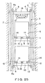
cage assembly 3 is hoisted by themain rope 4. In a case of 1:1 roping system, themain rope 4 is directly connected to theupper beam 16 of the cage frame 5 (Fig.24 ). And in a case of 2:1 roping system, themain rope 4 is wound around sheaves 17 provided on theupper beam 16 of the cage frame 5 (Fig.25 ). - When the upper and
lower cages cage doors 18 of thecages hall doors 19 of the floors and are opened and closed by a door-drivingunit 20.Hall sills 21 are provided on the floors, andcage sills 22 are provided on the floors of the upper andlower cages - In the conventional double deck elevators described above, a space "S" exists between the
upper cage 6 and thelower cage 7 and the door-driving unit is installed in the space "S". When the upper and lower cages move vertically in thehoistway 1, airflow flowing around the cages enters the space "S" and comes into collision with the door-drivingunit 20 and generates air turbulence. The air turbulence results in big noise that disturbs quietness and comfortableness in the upper andlower cages - It is therefore a general object of the present invention to provide a double deck elevator that can reduce air turbulence noise and improve quietness and comfortableness in the cages.
- According to the present invention there is provided a double deck elevator as defined by
claim 1. Preferred embodiments are defined in the dependent claims. - According to the present invention, since the space existing between an upper cage and a lower cage with covers for covering the space at a door-side, two lateral-sides and a backside of the space is covered with the covers, airflow flowing around the cages cannot enter the space and do not come into collisions with any devices arranged in the space, then the air do not cause any air turbulences. Consequently, noise caused by air turbulences is reduced and quietness and comfortableness in the cages is improved.
- Since the covers stabilize the airflow, the air resistance of the cages is reduced and the vertical moving speed of the cages can be increased.
- Since the space between the upper and lower cages is isolated from a general space in the hoistway by the covers, noise in the hoistway caused by the vertical moving of the cages cannot enter the cages through the space, and quietness and comfortableness in the cages is further improved. Further, the double deck elevator comprises a falling matter catching member for catching falling matters, such as dust or water, falling through a clearance between the door-side inner wall of the hoistway and the upper cage, and the door-side cover is provided with an opening through which the falling matter catching member approaches and moves apart from the door-side inner wall of the hoistway.
- The covers are preferably attached to at least one of the upper cage, the lower cage and the cage frame on which the cages are mounted respectively, via elastic material to absorb vertical distance change between the cages.
- For reducing air turbulence noise in the hoistway, and for reducing the air resistance of the cages, capsule type air guiding members can be arranged above the upper cages and below the lower cages respectively. The air guiding members guide the airflow into clearances between the inner walls of the hoistway and the outer side surfaces of the cages.
- The door-side cover is preferably positioned closer to the door-side inner wall of the hoistway than a door-driving unit that opens and closes the doors of the cages, to prevent the airflow from entering the space and coming into collision with the door-driving unit. In this case, the door-side cover is provided with slits through which the door links connecting the doors to the door-driving unit are inserted respectively. And the door-side cover is provided with slit-closing members that close a clearance between the periphery of the slit and the door link, to prevent the airflow from entering the space through the slit and causing the air turbulence noise.
- The door-side cover is preferably provided with an opening-closing member for closing the opening, and/or a clearance-closing member for closing a clearance between the falling matter catching member and the door-side cover, to prevent airflow from entering the space through the opening and/or through the clearance, and to prevent airflow from causing the air turbulence noise.
- For a better understanding of the invention as well as other objects and features thereof, reference is made to the following detailed description to be read in conjunction with the accompany drawings, and like reference characters designate corresponding parts in the several views, wherein:
-
Figs.1A and 1B are schematic front and side elevation views showing an example of a double deck elevator serving to explain certain features of the present invention, in whichFig.1A is a sectional drawing along the line X-X inFig.1B, and Fig.1B is a sectional drawing along the line Y-Y inFig.1A . -
Figs.2A and 2B are enlarged sectional front and side elevation views of the covers shown inFigs.1A and 1B . -
Figs.3A and 3B are enlarged sectional front and side elevation views of the covers of another example serving to explain certain features of the invention. -
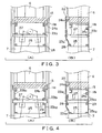
Figs.4A and 4B are enlarged sectional front and side elevation views of the covers of another example serving to explain certain features of the invention. -
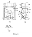
Figs.5A, 5B are enlarged sectional front and side views of the covers of an embodiment, andFig.5C is a sectional plan view of the falling matter catching member shown inFigs.5A and 5B . -
Figs.6A, 6B are sectional front and side elevation views of the covers of another example serving to explain certain features of the invention, andFig. 6C is a plan view of the covers shown inFig.6A and 6B . -
Figs.7A and 7B are schematic drawings showing a double deck elevator of another example serving to explain certain features of the present invention. -
Figs. 8A and 8B are schematic drawings showing a double deck elevator of another example serving to explain certain features of the present invention. -
Figs.9A and 9B are enlarged schematic front and side elevation views showing a double deck elevator of another example serving to explain certain features of the present invention. -
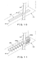
Fig.10 is a perspective view showing a slit-closing member used with the covers shown in Figas.9A and 9B. -
Fig. 11 is a perspective view showing a slit-closing member of another example serving to explain certain features of the invention. -
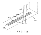
Fig.12 is a perspective view showing a slit-closing member of another example serving to explain certain features of the invention. -
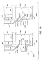
Figs.13A and 13B are enlarged schematic front and side views elevation views showing a double deck elevator of another embodiment of the present invention. -
Figs.14A and 14B are enlarged sectional side elevation views of the clearance-closing member shown inFigs.13A and 13B . -
Figs.15A and 15B are enlarged sectional side elevation views of the clearance-closing member of another embodiment. -
Figs.16A and 16B are enlarged sectional side elevation views of the clearance-closing member of another embodiment. -
Figs.17A and 17B are enlarged sectional side elevation views of the clearance-closing member of another embodiment. -
Figs.18A and 18B are enlarged side sectional elevations of an opening closing member. -
Figs.19A and 19B are enlarged side sectional elevations of an opening closing member of another embodiment -
Figs.20A and 20B are enlarged side sectional elevations of a noise insulating member. -
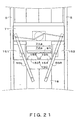
Fig.21 is an enlarged schematic front view showing a double deck elevator of another embodiment of the present invention. -
Fig.22 is an enlarged sectional side elevation view of the covers shown inFig.21 . -
Fig.23 is a schematic side sectional elevation view showing a double deck elevator of the prior art. -
Fig.24 is a schematic front elevation view showing another double deck elevator of the prior art. -
Fig.25 is a schematic front elevation view showing another double deck elevator of the prior art. - Referring to the attached drawings, in
Figs.1A and 1B , there is shown a double deck elevator comprising anupper cage 6 and alower cage 7 vertically movable together in ahoistway 1. - A space "S" existing between the
upper cage 6 and thelower cage 7 is covered by thecovers 23 including a door-side cover 23a, two lateral-side covers 23b and abackside cover 23c. That is, the space "S" is covered at a door-side, two lateral-sides and backside respectively. - As shown in
Figs.2A and 2B , the door-side cover 23a is formed so that its bottom half curves into the space "S" to absorb horizontal position difference between asill 22 of theupper cage 6 and aceiling 25 of thelower cage 7. And, all of these covers have smooth flat outer surfaces that are connected to the outer side surfaces of the upper andlower cages side cover 23a is provided with anopening 26 into which the front portion of a door-drivingunit 20 is inserted. - This construction enables airflow to flow smoothly around the space and
cages cages hoistway 1. Consequently, noise caused by airflow turbulence and air resistance of the cages are reduced. - As shown in
Figs.1A and 1B , since the upper andlower cages floor receiving frames rubber 13, vertical distance between the upper andlower cages cages - However, as shown in
Figs.2A and 2B , the top edge of the door-side cover 23a is fixed to acage sill 22 by means of an elastic material 24a, and its bottom edge is directly fixed to aceiling 25 of thelower cage 7. Also, the top edges of the lateral-side covers 23b are attached to a frame 11a extending from a door-side to a backside within acage frame 5 by means of aelastic material 24b, and its bottom edge is directly fixed to theceiling 25 of thelower cage 7. Further, the top edge of thebackside cover 23c is attached to the floor receiving frame 11b extending between two lateral-sides by means of aelastic material 24c, and its bottom edge is directly fixed to theceiling 25 of thelower cage 7. Theseelastic material cages - In addition, it is possible to insert an elastic material between the bottom edges of the covers and the
ceiling 25 of thelower cage 7. - In an example of the double deck elevator shown in
Figs.3A and 3B , the door-side cover 23a, the two lateral-side covers 23b and thebackside cover 23c are fixed to themiddle cage frame 27 at vertical middle portions thereof respectively. And,elastic materials sill 20 or the floor receiving frame 11a and 11b of the upper cage. Also,elastic materials 28 are inserted between the bottom edge of the respective covers and theceiling 25 of thelower cage 7. Accordingly, theseelastic materials cages - In an example of the double deck elevator shown in
Figs. 4A and 4B , respective covers are divided into upper and lower pieces. That is, the door-side cover 23a consists of upper piece 23a1 and the lower piece 23a2, the two lateral- side covers consist of upper pieces 23b1 and lower pieces 23b2, also the backside cover consists of upper piece 23c1 and lower piece 23c2. Bottom edges of the upper pieces 23a1, 23b1 and 23c1 are directly fixed to thecage frame 27, and the top edges of them are fixed to thesill 22 of the upper cage6, floor receiving frame 11a and 11b by means ofelastic material ceiling 25 of thelower cage 7, and the top edges of them are fixed to thecage frame 27 by means ofelastic material 29 respectively. Accordingly, theseelastic materials cages - In addition, it is possible to fix the bottom edges of the upper pieces 23a1, 23b1 and 23c1 by means of the
elastic materials sill 22 of the upper cage6, floor receiving frame 11a and 11b respectively. Also, it is possible to fix bottom edges of the lower pieces 23a2, 23b2 and 23c2 by means ofelastic materials 29 respectively, and to directly fix the top edges of them to thecage frame 27 respectively. - In an embodiment of the double deck elevator shown in
Figs. 5A and 5B , there is provided a fallingmatter catching device 30 at a door-side of the space betweencages hoistway 1 and theupper cage 6. This falling matter catchingdevice 30 has a fallingmatter catching plate 31 that swings around a horizontal axis to approach and move apart from the door-side inner wall of thehoistway 1, and a receiving dish 32 arranged in the space for receiving the falling matters caught by the catchingplate 31. - When the catching
plate 31 swings to approach the door-side inner wall of thehoistway 1 as shown inFigs.5A and 5B by the solid lines, the catchingplate 31 catches the fallingmatters 33 and guides them to the receiving dish 32 to protect passengers entering or exiting thelower cage 7 from such falling matters. - The door-
side cover 23a is provided with anopening 34 which is opened and closed by the catchingplate 31, and is provided with anopening closing member 35 attached along the periphery of theopening 34 that closes a clearance between the catchingplate 31 and the periphery of theopening 34 when the catchingplate 31 closes theopening 34 as shown inFig.5B by the phantom lines. - Since the airflow flowing along the door-
side cover 23a is guided by thefront cover 23a and the catchingplate 31, air turbulence noise is reduced. Furthermore, the catchingplate 31 blocks out the line of vision of a passenger ay the entrance of thelower cage 7 who looks up the passengers entering and exiting theupper cage 6. - In an example of the double deck elevator shown in
Figs.6A and 6B , a lot ofairflow guiding plates 36 extending vertically are provided on the outer surfaces of the door-side cover 23a, two lateral-side covers 23b and thebackside cover 23c. Theairflow guiding plates 36, as airflow protrusions, guide and stabilize the airflow flowing along the outer surfaces of the covers to reduce air turbulence noise. - In an example of the double deck elevator shown in
Figs. 7A and 7B , a capsule type upper and lower air-guidingmembers upper cage 6 and below thelower cage 7 respectively to guide an airflow into the clearances between inner walls of thehoistway 1 and outer side surfaces of the upper andlower cages - Also vibroisolating and
noise absorbing materials device - Furthermore, air-guiding
cones members member 37 and below the lower wind-guidingdevice 38 respectively. - In this example, since the capsule type air-guiding
member upper cage 6 and thelower cage 7 form a smooth streamline shape, airflow flow smoothly along the outer surfaces of the same and then air turbulence caused by thecages - Also, since the vibroisolating and
noise absorbing materials member - Furthermore, since the
airflow guiding cones member cages - In an example of the double deck elevator shown in
Figs. 8A and 8B , unevenconcave serrations 45 are provided on the outer surface of the capsule type air-guidingdevice guide rollers 42,main rope 43 andcompensation rope 44. - By this arrangement, the generation of the air turbulence is reduced by the uneven
concave serrations 45, and accordingly the noise reduction is achieved. In addition, it is possible to use uneven convex serrations to obtain the same effects. - In an example of the double deck elevator shown in
Figs.9A and 9B ,cage door 18 provided on thelower cage 7 is opened and closed by adoor driving unit 50 mounted on thehorizontal beam 9a of thecage frame 5. - The door-driving
unit 50 comprises arotating disc 52 driven by a drivingmotor 51, and a pair of connectinglinks rotating disc 52 at one ends thereof respectively. The other ends of the connectinglinks door links member 9b respectively by means ofpivot shafts respective support member 9b of thecage frame 5. Lower ends of the door links 55L, 55R are pivotally connected to thecage doors cage doors motor 51. - The
space 44 between the upper andlower cages cover 60 that guides the airflow flowing along thespace 44. Thecover 60 comprises a pair of upper and lower door-side covers 61, 62, a pair of right and left side covers 63, 64 and a pair of upper and lower backside covers 65, 66. - The upper door-
side cover 61 is positioned closer to the door-side inner wall la of thehoistway 1 than thedoor driving unit 50 and covers thedoor driving unit 50. And, the upper door-side cover 61 is provided with a pair ofslits 61a, through which door links 55L, 55R are inserted respectively. - By this arrangement, the upper door-
side cover 61 fully covers thedoor driving unit 50 and the top portions of the door links 55L, 55R without preventing the movement ofdoor links - Since the
cover 60 guides the airflow, the airflow cannot enter thespace 44 and cannot come into collisions with various unevenness existing in thespace 44, such as the door-drivingunit 50, and do not generate air turbulence. As a result, air turbulence noise can be effectively reduced when thecages hoistway 1 at a high speed, and quietness and comfortableness in thecages - At the same time, since the
space 44 is separated from the inner space of thehoistway 1 by thecover 60, noise in thehoistway 1 cannot enter thecages space 44, then quietness and comfortableness in thecages - And, since the
cover 60 guides the airflow into clearances between the inner walls of thehoistway 1 and the outer side surfaces of thecages cages cages - In an example of the double deck elevator shown in
Fig.10 , there is provided a slit-closingmember 67 made of an elastic material, such as a rubber film or a thin plastic film, which closes a clearance between the periphery of theslit 61a and thedoor link 55. This slit-closingmember 67 has a slit 67a extending along the moving direction of thedoor link 55, through which thedoor link 55 is inserted, and allows the displacement of thedoor link 55 by its elastic deformation caused by contact with thedoor link 55. By this arrangement, the airflow cannot enter or exit from thespace 44 through theslit 61a, and do not generate air turbulence noise. As a result, quietness and comfortableness in thecages - In an example of the double deck elevator shown in
Fig.11 , there is provided a bellows type slit-closingmember 68 made of an elastic material, such as a rubber film or a thin plastic film. This bellows type slit-closingmember 68 comprises a pair ofbellows 68a, 68b that expand and contract along the moving direction of thedoor link 55 and closes the clearance between the periphery of theslit 61a and the door-link 55. This slit-closingmember 68 has an aperture through which thedoor link 55 is inserted, and allows the displacement of thedoor link 55 by its elastic deformation caused by contact with thedoor link 55. By this arrangement, airflow cannot enter or exit thespace 44 through theslit 61a, and do not generate air turbulence noise. As a result, quietness and comfortableness in thecages - In an example of the double deck elevator shown in
Fig. 12 , there is provided a brush type slit-closingmember 69 made of an elastic material, such as a plastic bristles, which closes a clearance between the periphery of theslit 61a and thedoor link 55. This brush type slit-closingmember 69 comprises a pair of front andrear brushes slit 69a extending along moving direction of thedoor link 55. Theslit 69a allows the displacement of thedoor link 55 by its elastic deformation caused by the contact with thedoor link 55. By this arrangement, the airflow cannot enter or exit from thespace 44 through theslit 61a, and do not generate air turbulence noise. As a result, the quietness and the comfortableness in thecages - In an embodiment of the double deck elevator shown in
Figs. 13 and14 , thespace 44 between the upper andlower cages cover 70, which comprises a pair of upper and lower door-side covers 71,72, a pair of lateral-sides covers 73,74 and a pair of backside covers 75, 76. - In the
space 44, there is provided a falling matter catching means 80 for catching the falling matter, such as dirt or water, falling from the clearance between the door-side inner wall la of thehoistway 1 and theupper cage 6. - The upper door-
side cover 71 has a inclinedlower portion 71a entering thespace 44 at its lateral mid section, which absorb the horizontal position difference between the upper andlower cages lower cages - The lower door-
side cover 72 has anopening 72a through which a fallingmatter catching plate 81 of thedevice 80 approaches and moves apart from the door-side inner wall la of thehoistway 1. Also, the lower door-side cover 72 has a vertical wall 42a positioned closer to the door-side inner wall la of thehoistway 1 than the fallingmatter catching device 80, to prevent the air flow from contacting the fallingmatter catching device 80 and generating air turbulence noise. - By this arrangement, even when a falling
matter catching device 80 is provided in thespace 44, the door-side cover lower cages - The falling
matter catching device 80 comprises the catchingplate 81 mentioned above which approaches and leaves the door-side inner wall la of thehoistway 1, and a drivingmotor 83 which swings the catchingplate 81 around the horizontal swingingaxis 82. - When the upper and
lower cages hoistway 1, the catchingplate 81 approaches the door-side inner wall la of thehoistway 1 and extends horizontally as shown inFigs. 13B and14A so that itsfree end 81a contacts the door-side inner wall la. And this catchingplate 81 receives the falling matter to prevent the falling matter from dropping toward the passengers entering and exiting thelower cage 7. - Before the upper and
lower cages plate 81 moves apart from the door-side inner wall la so as not to prevent vertical movement of thecages plate 81 inclines parallel to the inclinedlower portion 71a of the upper door-side cover 71 as shown inFigs.14B , so that the airflow flows smoothly along the outer surface of the upper and lower door-side cover - While, the inclined
lower portion 71a of the upper door-side cover 71 serves as a stopper for limiting the moving stroke of the catchingplate 81. As a result, it is not necessary to provide the fallingmatter catching device 80 with the stopper. - Furthermore, a horizontally extending clearance-closing
member 71b made of sponge rubber strip is provided on the inclinedlower portion 71a, and thefree end 81a of the catchingplate 81 strongly presses this clearance-closingmember 71b against the inclinedlower portion 71a. - In this manner, the clearance between the upper door-
side cover 71 and the fallingmatter caching plate 81 is surely closed, and the airflow can not enter thespace 44 through the clearance and do not generate air turbulence noise. - In an embodiment of the double deck elevator shown in
Figs.15A, 15B , there is provided a clearance-closing means 90 for closing the clearance between thevertical wall 72b of the lower door-side cover 72 and the fallingmatter catching plate 81. - The clearance-closing
member 90 comprises a slidingplate 91 slidably held by thevertical wall 72b of the lower door-side cover 72, and a connectinglink 92 which is pivotably connected to the lower surface of the fallingmatter catching plate 81 at its one end via a connectingportion 81b and to the top end of the slidingplate 91 at its another end via connecting portion 91a. - The sliding
plate 91 slides downwardly due to the weight thereof when the catchingplate 81 approaches the door-side inner wall la of thehoistway 1 as shown inFig.15A . On the contrary, the slidingplate 91 slides upwardly pulled by the connectinglink 92 when the catchingplate 81 moves apart from the door-side inner wall la of thehoistway 1 as shown inFig.15B . - By this arrangement, since the
slide plate 91 always closes the clearance between thevertical wall 72b of the lower door-side cover 72 and the catchingplate 81 without disturbing the movement of the catchingplate 81, the airflow flows smoothly along the door-side covers 71, 72, and does not enter thespace 44 through the clearance and does not generate the air turbulence noise. - In an embodiment of the double deck elevator shown in
Figs.16A, 16B , there is provided a clearance-closing means 100 for closing the clearance between thevertical wall 72b of the lower door-side cover 72 and the fallingmatter catching plate 81. - The clearance-closing means 100 comprises a
pivot plate 101 pivotably connected to thevertical wall 72b of the lower door-side cover 72 at its lower end via a horizontally extendingaxis 102. And thispivot plate 101 is always biased to rotate around theaxis 102 by biasing means (not shown) such as a torsion bar, so that the upper end 101a of thepivot plate 101 always contacts the lower surface of the catchingplate 81. - When the catching
plate 81 approaches the door-side inner wall la of thehoistway 1, the pivotingplate 101 counterclockwisely pivots around thehorizontal axis 102 opposing to the biasing forces and inclines toward the door-side inner wall la as shown inFig.16A . On the contrary, when the catchingplate 81 moves apart from the inner wall la of thehoistway 1, the pivot plate pivots clockwisely biased by the biasing means as shown inFig.16B . - By this arrangement, since the
pivot plate 101 always closes the clearance between thevertical wall 72b of the lower door-side cover 72 and the catchingplate 81 without disturbing the movement of the catchingplate 81, the airflow flows smoothly along the door-side covers 71, 72, and does not enter thespace 44 through the clearance and does not generate the air turbulence noise. - In addition, it is possible to eliminate the biasing means, and to connect the top edge 101a of the
pivot plate 101 via a connecting link (as shown inFig.15 ) to the catchingplate 81. - In an embodiment of the double deck elevator shown in
Figs.17A, 17B , there is provided a clearance-closing means 110 for closing the clearance between thevertical wall 72b of the lower door-side cover 72 and the fallingmatter catching plate 81. - The clearance-closing means 110 comprises a
bellows 111 made of an elastic material such as a rubber plate or plastic film, which is connected to the fallingmatter catching plate 81 via connectingportion 112 at upper end thereof, and is connected to the lower door-side cover 72 via connectingportion 113 at lower end thereof. - When the catching
plate 81 approaches the door-side inner wall la of thehoistway 1, thebellows 111 contracts as shown inFig.17A . On the contrary, when the catchingplate 81 moves apart from the inner wall la of thehoistway 1, the bellows expands as shown inFig.17B . - By this arrangement, since the
bellows 111 always closes the clearance between thevertical wall 72b of the lower door-side cover 72 and the catchingplate 81 without disturbing the movement of the catchingplate 81, the airflow flows smoothly along the door-side covers 71, 72, and does not enter thespace 44 through the clearance and does not generate the air turbulence noise. In addition, instead of thebellows 111, it is possible to use straight elastic material that is expandable and contractible such as thin rubber film. - In an embodiment of the double deck elevator shown in
Figs.18A, 18B , there is provided a clearance-closing means 120 for closing the clearance between thevertical wall 72b of the lower door-side cover 72 and the fallingmatter catching plate 81. - The clearance-closing means 120 comprises a
closing plate 121, which is fixed to the lower surface of the catchingplate 81 at itsbase end 121a and moves together with the catchingplat 81. - When the catching
plate 81 approaches the door-side inner wall la of thehoistway 1, thefree end 121b of theclosing plate 121 is in thespace 44 apart from the inner surface of thevertical wall 72b of the lower door-side cover 72 as shown inFig.18A . On the contrary, when the catchingplate 81 moves apart from the inner wall la of thehoistway 1 and itsfree end 81a contacts the inclinedlower portion 71a of the upper door-side cover 71 via the clearance-closingmember 71b, thefree end 121b of theclosing plate 121 rests on the inner surface of thevertical wall 72b and closes the clearance between thevertical wall 72b and the fallingmatter catching plate 81. - By this arrangement, since the
closing plate 121 closes the clearance between thevertical wall 72b and the catchingplate 81 without disturbing the movement of the catchingplate 81, the airflow flows smoothly along the door-side covers 71, 72, and does not enter thespace 44 through the clearance and does not generate the air turbulence noise. - In an embodiment of the double deck elevator shown in
Figs.19A, 19B , there is provided an opening closing means 130 for closing theopening 72a of the lower door-side cover 72. - The opening closing means 130 comprises a
closing plate 131, which is fixed to the lower surface of the catchingplate 81 at its oneend 131a and moves together with the catching plate. 81. - When the catching
plate 81 approaches the door-side inner wall la of thehoistway 1, thefree end 131b of theclosing plate 131 is in thespace 44 apart from the inner surface of thevertical wall 72b of the lower door-side cover 72 as shown inFig.19A . On the contrary, when the catchingplate 81 moves apart from the inner wall la of thehoistway 1, thefree end 131b of theclosing plate 131 rests on the inner surface of thevertical wall 72b and stops the movement of the catchingplate 81, at the same time, the closing plate entirely closes theopening 72a of the lower door-side cover 72 as shown inFig.19B . - Furthermore, the
closing plate 131 has an outer surface 131c which is connected to those of the door-side covers 72 without any steps, when theclosing plate 131 closes theopening 72a. - By this arrangement, since the
closing plate 131 closes theopening 72a without disturbing the movement of the catchingplate 81, the airflow flows smoothly along the door-side covers 71, 72, and does not enter thespace 44 through theopening 72a and does not generate the air turbulence noise. - In an embodiment of the double deck elevator shown in
Figs.20A, 20B , there is provided a box like noise-insulatingmember 140 for insulating the noise entering thespace 44 between the upper andlower cages opening 72a of the lower door-side cover 72. - The noise-insulating
member 140 is open toward theopening 72a, and is connected to thelower end 71c of the upper door-side cover 71 at its frontupper edge 141, and is further connected to the lower door-side cover 72 at its frontlower edge 142. It is preferable to attach the noise absorbing material, such as glass fiber, to the inner surface of the noise-insulatingmember 140. - By this arrangement, since the noise entering from the
opening 72a is insulated and absorbed in the noise-insulatingmember 140 and cannot reach the upper andlower cages matter catching plate 81, quietness and comfortableness in the upper andlower cages - In an embodiment of the double deck elevator shown in
Figs.21 and22 , there is provided a fallingmatter storing box 84 for storing the falling matters caught by the fallingmatter catching plate 81. That is, the falling matters caught by the catchingplate 81 is guided to drop into thestoring box 84 when the catchingplate 81 moves apart from the door-side inner wall la and inclines as shown inFig.23 by phantom lines. - Therefore, it is necessary to remove the falling matters stored in the
storing box 84, when the maintenance or inspection of the double deck elevators is performed. However, it is difficult to remove the falling matters stored in thestoring box 84 in the above mentioned double deck elevator, due to the presence of the lower door-side cover 72. - For this reason, the lower door-
side cover 150 in this embodiment is divided into fourparts Fig.21 . Especially, theparts storing box 84 are smaller than the floor-side door openings respectively. In other words, the horizontal width of theparts side doors 19 open. - Furthermore, as shown in
Fig.22 , thedoor parts bracket 155 fixed on thelower cage 7 by means of butter fly screws 156 andnuts 157 respectively. - Therefore, when the double deck elevator of this embodiment is inspected or maintained, the worker on the floor can easily remove the
parts parts lower cage 7, it is easy to access thestore box 84 to remove the stored falling matters. Similarly, it is easy to mount theparts lower cage 7. and it is to be understood that changes and variations may be made without departing from the spirit or scope of the following claims.
Claims (25)
- A double deck elevator comprising:an upper cage (6) and a lower cage (7) vertically movable together in a hoistway (1);characterized by comprisingcovers (23;60;70) for covering a space (S;44) between the upper cage (6) and the lower cage (7) at a door-side, two lateral-sides and a backside of the space (S;44); anda falling matter catching member (30;80) for catching falling matters falling through a clearance between a door-side inner wall (1a) of the hoistway (1) and the upper cage (6),said catching member (30;80) is movably arranged in the space (S;44) to approach and move apart from the door-side inner wall (1a) when the upper cage (6) and the lower cage (7) stop vertical moving in the hoistway (1), andat least one of said covers (23;70) which covers the space (S;44) at the door-side has an opening (34;72a) through which the falling matter catching member (30;80) can approach and move apart from the door-side inner wall (1a).
- A double deck elevator according to claim 1, wherein said falling matter catching member (80) contacts the cover (70,71,72) which covers the space (44) at the door-side, when said falling matter catching member (80) moves apart from the door-side inner wall (1a) of the hoistway (1).
- A double deck elevator according to claim 2, wherein said cover (70,71,72) which covers the space (44) at the door-side serves as a stopper for limiting a moving stroke of the falling matter catching member (80), when the falling matter catching member (80) moves apart from the door-side inner wall (1a) of the hoistway (1).
- A double deck elevator according to claim 2, further comprising a clearance-closing member (71b;90;100) for closing a clearance between the falling matter catching member (80) and the cover (70,71,72) which covers the space (44) at the door-side when the falling matter catching member (80) moves apart from the door-side inner wall (1a) of the hoistway (1).
- A double deck elevator according to claim 4, wherein said clearance-closing member comprises a strip (71b) made of an elastic material attached on at least one of the falling matter catching member (80) and the cover (70,71,72) which covers the space (44) at the door-side, said strip (71b) elastically deforms when pressed against the cover (70,71,72) which covers the space (44) at the door-side by the falling matter catching member (80).
- A double deck elevator according to claim 4, wherein said clearance-closing member (90) comprises a plate (91), said plate (91) being connected to the falling matter catching member (80) at one end thereof by means of a connecting link (92) and is slidably held by the cover (70,71,72) which covers the space (44) at the door-side at another end thereof.
- A double deck elevator according to claim 4, wherein said clearance-closing member (100) comprises a plate (101), said plate (101) being pivotally connected to the door-side cover (70,71,72) at one end thereof and being biased by a biasing means so that the another end (101a) of the clearance-closing member (100) always contacts the falling matter catching member (80).
- A double deck elevator according to claim 4, wherein said clearance-closing member (100) comprises a plate (101), said plate (101) being connected to the falling matter catching member (80) at one end thereof by means of a connecting link and being pivotably connected to the door-side cover (70,71,72) at another end thereof.
- A double deck elevator according to claim 4, wherein
said clearance-closing member (110,111) is connected to the falling matter catching member (80) at one end thereof and is connected to the door-side cover (70,71,72) at another end thereof, and
said clearance-closing member (110,111) being made of an elastic material and expanding and contracting in accordance with the movement of the falling matter catching member (80). - A double deck elevator according to anyone of claims 1 to 9, further comprising an opening closing member (120,121;130,131) attached to the falling matter catching member (80) for closing the opening of the cover (70,71,72) when the falling matter catching member (80) moves apart from the door-side inner wall (1a) of the hoistway (1).
- A double deck elevator according to anyone of claims 1 to 10, further comprising a noise insulating member (140) arranged in the space (44) for insulating noise entering through the opening of the door-side cover (70,71,72).
- A double deck elevator according to anyone of claims 1 to 11, wherein said door-side cover (70,71,72,150) is divided into parts (151-154) which are smaller than a floor-side door opening.
- A double deck elevator according to claim 12, wherein said parts (151-154) of the door-side cover (70,71,72,150) are removably mounted to at least one of the upper cage (6), the lower cage (7) and a cage frame (5) by means of mounting means manually operable from the floor-side door opening.
- A double deck elevator according to any one of claims 1 to 13, wherein outer surfaces of said covers (23;60;70) and outer surfaces of the upper cage (6) and the lower cage (7) are connected to each other without difference in level.
- A double deck elevator according to any one of claims 1 to 14, wherein said covers (23) are connected to at least one of the upper cage (6) and the lower cage (7) by means of an elastic member (24;28;29) for absorbing a distance change between the upper cage (6) and the lower cage (7).
- A double deck elevator according to anyone of claims 1 to 15, wherein said covers (23) are provided with a plurality of protrusions (36) on outer surfaces thereof for guiding an airflow flowing along the outer surfaces.
- A double deck elevator according to anyone of claims 1 to 15, further comprising:an upper airflow guiding member (37) arranged above the upper cage (6) for guiding an airflow into clearances between inner walls of the hoistway (1) and outer side surfaces of the upper cage (6); anda lower airflow guiding member (38) arranged below the lower cage (7) for guiding an airflow into clearances between inner walls of the hoistway (1) and outer side surfaces of the lower cage (7);wherein said upper and lower airflow guiding members (37,38) are in the form of a capsule.
- A double deck elevator according to claim 17, further comprising noise absorbing members (39) attached to at least one of the inner surfaces of the covers (23) and the upper and lower airflow guiding members (37,38).
- A double deck elevator according to claim 17 or 18, further comprising:an upper airflow guiding cone (40) arranged on the upper airflow guiding member (37) for guiding an airflow to the outer surfaces of the upper airflow guiding member (37); anda lower airflow guiding cone (41) arranged below the lower airflow guiding member (38) for guiding an airflow to the outer surfaces of the lower airflow guiding member (38).
- A double deck elevator according to claim 17, wherein said upper and lower airflow guiding members (37,38) are provided with uneven serrations (45) on outer surfaces thereof respectively.
- A double deck elevator according to anyone of claims 1 to 20, wherein at least one (61) of the covers (60) which covers the space (44) at the door-side of the space (44) is positioned closer to a door-side inner wall (1a) of the hoistway (1) than a door driving unit (50) for opening and closing the doors (18) of the cages (6,7).
- A double deck elevator according to claim 21, wherein said at least one (61) of the covers (60) which covers the space (44) at the door-side is provided with a slit (61a) through which a door link (55) connecting the doors (18) to the door-driving unit (50) is inserted.
- A double deck elevator according to claim 22, further comprising a slit-closing member (67) made of an elastic material, which closes clearances between the periphery of the slit (61a) and the door links (55) and at the same time allows the displacement of said door links (55) by elastic deformation thereof.
- A double deck elevator according to claim 22, further comprising a bellows type slit-closing member (68) made of an elastic material, which closes a clearance between the periphery of said slit (61a) and said door link (55) and at the same time allows a displacement of the door link (55) by elastic expansion and contraction thereof.
- A double deck elevator according to claim 22, further comprising a brush type slit-closing member (69) made of elastic bristles, which closes a clearance between a periphery of the slit (61a) and said door link (55) and at the same time allows a displacement of the door link (55) by elastic deflection thereof.
Applications Claiming Priority (4)
| Application Number | Priority Date | Filing Date | Title |
|---|---|---|---|
| JP2000056981 | 2000-03-02 | ||
| JP2000056981A JP2001240346A (en) | 2000-03-02 | 2000-03-02 | Double deck elevator |
| JP2000392049 | 2000-12-25 | ||
| JP2000392049A JP4671499B2 (en) | 2000-12-25 | 2000-12-25 | Double deck elevator |
Publications (3)
| Publication Number | Publication Date |
|---|---|
| EP1129978A2 EP1129978A2 (en) | 2001-09-05 |
| EP1129978A3 EP1129978A3 (en) | 2004-02-04 |
| EP1129978B1 true EP1129978B1 (en) | 2012-05-09 |
Family
ID=26586597
Family Applications (1)
| Application Number | Title | Priority Date | Filing Date |
|---|---|---|---|
| EP01105111A Expired - Lifetime EP1129978B1 (en) | 2000-03-02 | 2001-03-02 | Double deck elevator |
Country Status (5)
| Country | Link |
|---|---|
| US (3) | US6615952B2 (en) |
| EP (1) | EP1129978B1 (en) |
| KR (1) | KR100435242B1 (en) |
| CN (1) | CN1160243C (en) |
| TW (1) | TWI234543B (en) |
Families Citing this family (14)
| Publication number | Priority date | Publication date | Assignee | Title |
|---|---|---|---|---|
| US6615952B2 (en) * | 2000-03-02 | 2003-09-09 | Kabushiki Kaisha Toshiba | Double deck elevator |
| JP4732577B2 (en) * | 2000-11-24 | 2011-07-27 | 東芝エレベータ株式会社 | Elevator car rescue device |
| EP1342690A1 (en) * | 2002-03-04 | 2003-09-10 | Inventio Ag | System for positioning at least one deck of a multiple deck elevator cabin of an elevator |
| JP4107858B2 (en) * | 2002-03-22 | 2008-06-25 | 東芝エレベータ株式会社 | Double deck elevator |
| JP2005008414A (en) * | 2003-06-18 | 2005-01-13 | Inventio Ag | Lift installation, method for operating lift installation, and method for realizing modernizing lift installation |
| JP4322579B2 (en) * | 2003-07-28 | 2009-09-02 | 東芝エレベータ株式会社 | Elevator door sealing device |
| JP5481170B2 (en) * | 2009-11-18 | 2014-04-23 | 株式会社日立製作所 | Double deck elevator device |
| US8807255B2 (en) * | 2012-09-24 | 2014-08-19 | Caterpillar Paving Products Inc. | Engine hot air deflector |
| AT513930B1 (en) * | 2012-12-20 | 2020-10-15 | Tgw Mechanics Gmbh | Shelf storage system with conveyor vehicle lifting device |
| DE102013019231A1 (en) * | 2013-11-16 | 2015-05-21 | Eisenmann Ag | Device for treating objects |
| DE102014012595A1 (en) * | 2014-08-27 | 2016-03-03 | Eisenmann Ag | Device for treating objects |
| EP3031766A1 (en) * | 2014-12-11 | 2016-06-15 | KONE Corporation | Elevator car |
| DE202016100400U1 (en) * | 2016-01-28 | 2017-01-31 | Kone Corporation | elevator |
| CN109095326B (en) * | 2018-07-27 | 2023-10-24 | 天津市奥瑞克电梯有限公司 | Novel car of making an uproar falls in ventilation |
Family Cites Families (32)
| Publication number | Priority date | Publication date | Assignee | Title |
|---|---|---|---|---|
| US575684A (en) * | 1897-01-26 | Dental chair | ||
| US95800A (en) * | 1869-10-12 | Improvement in machine for wiring blind-rods | ||
| US958000A (en) * | 1909-06-15 | 1910-05-17 | James Peterson | Chair. |
| US1511701A (en) * | 1922-02-27 | 1924-10-14 | Edwin R Angell | Antidraft |
| US1728306A (en) * | 1927-02-23 | 1929-09-17 | F O Richey | Mat |
| US1738729A (en) * | 1928-09-21 | 1929-12-10 | Elevator Supplies Co Inc | Well protection device for elevators |
| US2557827A (en) * | 1944-10-23 | 1951-06-19 | Goodrich Co B F | Sealing closure |
| US3472488A (en) * | 1967-07-05 | 1969-10-14 | Den Tal Ez Chair Mfg Co | Foldable lift device |
| US3748923A (en) * | 1971-08-11 | 1973-07-31 | Caterpillar Tractor Co | Environmental seal for a transmission shift lever |
| JPS557132Y2 (en) * | 1975-02-21 | 1980-02-18 | ||
| US3982718A (en) * | 1975-07-31 | 1976-09-28 | Dentsply Research & Development Corporation | Operatory chair operating mechanism |
| US4058191A (en) * | 1976-10-06 | 1977-11-15 | Westinghouse Electric Corporation | Elevator system including an elevator car having door operated sealing devices adjacent door opening |
| DE2807819A1 (en) * | 1978-02-23 | 1979-08-30 | Int Harvester Co | DEVICE FOR CLOSING SLOT-SHAPED OPENINGS TO ADD THROUGH PIVOTING, HAND OR FOOT-OPERATED CONTROL LEVERS WITH EACH OPENING ASSIGNED SEALING ELEMENT |
| JPS61188384A (en) * | 1985-02-12 | 1986-08-22 | 三菱電機株式会社 | Cage chamber for double deck elevator |
| US4941797A (en) * | 1987-02-24 | 1990-07-17 | C.M. Smillie & Company | Power-operated lift and presenting mechanism |
| JPH03158377A (en) * | 1989-11-13 | 1991-07-08 | Mitsubishi Electric Corp | Speed reducer for elevator |
| US5018602A (en) * | 1990-03-21 | 1991-05-28 | Otis Elevator Company | Reduction of noise and vibration in an elevator car by selectively reducing air turbulence |
| JP2547282B2 (en) * | 1991-02-27 | 1996-10-23 | 三菱電機株式会社 | Elevator car |
| JP3158377B2 (en) | 1991-09-27 | 2001-04-23 | 株式会社ソフィア | Card-type gaming machine |
| JP2896260B2 (en) * | 1992-01-08 | 1999-05-31 | 株式会社東芝 | Elevator door equipment |
| JPH06255955A (en) * | 1993-03-09 | 1994-09-13 | Toshiba F Ee Syst Eng Kk | Double deck elevator basket |
| GB2280662B (en) * | 1993-07-30 | 1997-04-16 | Hitachi Ltd | A elevator car,and an elevator system incorporating such an elevator car |
| US5377784A (en) * | 1993-09-08 | 1995-01-03 | The Peelle Company | Pass door fire lintel |
| JPH0977436A (en) * | 1995-09-18 | 1997-03-25 | Toshiba Fa Syst Eng Kk | Double deck elevator sill blocking device |
| JP4070837B2 (en) * | 1997-03-06 | 2008-04-02 | 東芝エレベータ株式会社 | Double deck elevator sill blocker |
| JP3345565B2 (en) * | 1997-04-11 | 2002-11-18 | 森ビル株式会社 | Adjustable double deck elevator |
| US5960910A (en) * | 1997-12-31 | 1999-10-05 | Otis Elevator Company | Double deck elevator cab |
| US6119815A (en) * | 1998-02-20 | 2000-09-19 | Ziegler; Kimberly | Safety skirt |
| KR19990075729A (en) * | 1998-03-24 | 1999-10-15 | 이종수 | Upper Car Shifter of Double Tech Elevator |
| EP0982260A1 (en) * | 1998-08-17 | 2000-03-01 | Inventio Ag | Device for minimising air noise on a high speed elevator car |
| US6615952B2 (en) * | 2000-03-02 | 2003-09-09 | Kabushiki Kaisha Toshiba | Double deck elevator |
| JP4666755B2 (en) * | 2000-12-13 | 2011-04-06 | 東芝エレベータ株式会社 | Double deck elevator |
-
2001
- 2001-03-01 US US09/795,357 patent/US6615952B2/en not_active Expired - Fee Related
- 2001-03-02 EP EP01105111A patent/EP1129978B1/en not_active Expired - Lifetime
- 2001-03-02 KR KR10-2001-0010827A patent/KR100435242B1/en not_active Expired - Fee Related
- 2001-03-02 CN CNB011093595A patent/CN1160243C/en not_active Expired - Fee Related
- 2001-03-02 TW TW090104855A patent/TWI234543B/en not_active IP Right Cessation
-
2003
- 2003-07-17 US US10/620,467 patent/US7077240B2/en not_active Expired - Fee Related
- 2003-07-17 US US10/620,384 patent/US7287624B2/en not_active Expired - Fee Related
Also Published As
| Publication number | Publication date |
|---|---|
| CN1160243C (en) | 2004-08-04 |
| CN1311157A (en) | 2001-09-05 |
| US20010018996A1 (en) | 2001-09-06 |
| US7287624B2 (en) | 2007-10-30 |
| KR20010087279A (en) | 2001-09-15 |
| KR100435242B1 (en) | 2004-06-11 |
| EP1129978A3 (en) | 2004-02-04 |
| TWI234543B (en) | 2005-06-21 |
| EP1129978A2 (en) | 2001-09-05 |
| US6615952B2 (en) | 2003-09-09 |
| US20040016605A1 (en) | 2004-01-29 |
| US7077240B2 (en) | 2006-07-18 |
| US20040094369A1 (en) | 2004-05-20 |
Similar Documents
| Publication | Publication Date | Title |
|---|---|---|
| EP1129978A2 (en) | Double deck elevator | |
| US3426480A (en) | Door assembly | |
| JPH06321466A (en) | Elevator device and its basket room entrance structure | |
| US5715913A (en) | Door sill for an elevator car | |
| JPH04313589A (en) | Elevator car device | |
| KR20130125794A (en) | Door device for elevator | |
| JP3388458B2 (en) | Clean elevator | |
| JP5836228B2 (en) | Elevator door device | |
| GB2280662A (en) | Streamlined elevator car | |
| JP4540176B2 (en) | Elevator car equipment | |
| JP7328085B2 (en) | Platform door device | |
| JP5495613B2 (en) | Elevator car | |
| KR102682651B1 (en) | Apparatus for preventing door from escaping for elevator | |
| JP5080634B2 (en) | Double deck elevator | |
| JP7231072B1 (en) | elevator door sill | |
| KR102886540B1 (en) | Elevator preventing falling accident due to door separation | |
| JPH06156953A (en) | Door device for elevator | |
| JP6373745B2 (en) | View elevator car | |
| JP2024083988A (en) | Automatic door system and method for connecting automatic door systems | |
| JP7099630B2 (en) | Elevator landing system | |
| JP2001240346A (en) | Double deck elevator | |
| JP2024083989A (en) | Automatic door guardrails and automatic door devices | |
| JP6301436B1 (en) | Elevator car door device | |
| JPH08127485A (en) | Soundproof type elevator cage | |
| JP2024118601A (en) | Landing door |
Legal Events
| Date | Code | Title | Description |
|---|---|---|---|
| PUAI | Public reference made under article 153(3) epc to a published international application that has entered the european phase |
Free format text: ORIGINAL CODE: 0009012 |
|
| 17P | Request for examination filed |
Effective date: 20010302 |
|
| AK | Designated contracting states |
Kind code of ref document: A2 Designated state(s): AT BE CH CY DE DK ES FI FR GB GR IE IT LI LU MC NL PT SE TR |
|
| AX | Request for extension of the european patent |
Free format text: AL;LT;LV;MK;RO;SI |
|
| PUAL | Search report despatched |
Free format text: ORIGINAL CODE: 0009013 |
|
| AK | Designated contracting states |
Kind code of ref document: A3 Designated state(s): AT BE CH CY DE DK ES FI FR GB GR IE IT LI LU MC NL PT SE TR |
|
| AX | Request for extension of the european patent |
Extension state: AL LT LV MK RO SI |
|
| AKX | Designation fees paid |
Designated state(s): DE FI FR GB |
|
| 17Q | First examination report despatched |
Effective date: 20080528 |
|
| GRAP | Despatch of communication of intention to grant a patent |
Free format text: ORIGINAL CODE: EPIDOSNIGR1 |
|
| GRAS | Grant fee paid |
Free format text: ORIGINAL CODE: EPIDOSNIGR3 |
|
| GRAA | (expected) grant |
Free format text: ORIGINAL CODE: 0009210 |
|
| AK | Designated contracting states |
Kind code of ref document: B1 Designated state(s): DE FI FR GB |
|
| REG | Reference to a national code |
Ref country code: GB Ref legal event code: FG4D |
|
| REG | Reference to a national code |
Ref country code: DE Ref legal event code: R096 Ref document number: 60146524 Country of ref document: DE Effective date: 20120705 |
|
| PLBE | No opposition filed within time limit |
Free format text: ORIGINAL CODE: 0009261 |
|
| STAA | Information on the status of an ep patent application or granted ep patent |
Free format text: STATUS: NO OPPOSITION FILED WITHIN TIME LIMIT |
|
| 26N | No opposition filed |
Effective date: 20130212 |
|
| REG | Reference to a national code |
Ref country code: DE Ref legal event code: R097 Ref document number: 60146524 Country of ref document: DE Effective date: 20130212 |
|
| PG25 | Lapsed in a contracting state [announced via postgrant information from national office to epo] |
Ref country code: FI Free format text: LAPSE BECAUSE OF NON-PAYMENT OF DUE FEES Effective date: 20130302 |
|
| REG | Reference to a national code |
Ref country code: FR Ref legal event code: PLFP Year of fee payment: 16 |
|
| REG | Reference to a national code |
Ref country code: FR Ref legal event code: PLFP Year of fee payment: 17 |
|
| REG | Reference to a national code |
Ref country code: FR Ref legal event code: PLFP Year of fee payment: 18 |
|
| PGFP | Annual fee paid to national office [announced via postgrant information from national office to epo] |
Ref country code: DE Payment date: 20190219 Year of fee payment: 19 Ref country code: FR Payment date: 20190111 Year of fee payment: 19 Ref country code: GB Payment date: 20190227 Year of fee payment: 19 |
|
| REG | Reference to a national code |
Ref country code: DE Ref legal event code: R119 Ref document number: 60146524 Country of ref document: DE |
|
| PG25 | Lapsed in a contracting state [announced via postgrant information from national office to epo] |
Ref country code: DE Free format text: LAPSE BECAUSE OF NON-PAYMENT OF DUE FEES Effective date: 20201001 Ref country code: FR Free format text: LAPSE BECAUSE OF NON-PAYMENT OF DUE FEES Effective date: 20200331 |
|
| GBPC | Gb: european patent ceased through non-payment of renewal fee |
Effective date: 20200302 |
|
| PG25 | Lapsed in a contracting state [announced via postgrant information from national office to epo] |
Ref country code: GB Free format text: LAPSE BECAUSE OF NON-PAYMENT OF DUE FEES Effective date: 20200302 |