EP1129896A1 - A motor vehicle safety apparatus - Google Patents
A motor vehicle safety apparatus Download PDFInfo
- Publication number
- EP1129896A1 EP1129896A1 EP00301635A EP00301635A EP1129896A1 EP 1129896 A1 EP1129896 A1 EP 1129896A1 EP 00301635 A EP00301635 A EP 00301635A EP 00301635 A EP00301635 A EP 00301635A EP 1129896 A1 EP1129896 A1 EP 1129896A1
- Authority
- EP
- European Patent Office
- Prior art keywords
- pedal
- motor vehicle
- foot
- support means
- recess
- Prior art date
- Legal status (The legal status is an assumption and is not a legal conclusion. Google has not performed a legal analysis and makes no representation as to the accuracy of the status listed.)
- Withdrawn
Links
Images

Classifications
-
- B—PERFORMING OPERATIONS; TRANSPORTING
- B60—VEHICLES IN GENERAL
- B60R—VEHICLES, VEHICLE FITTINGS, OR VEHICLE PARTS, NOT OTHERWISE PROVIDED FOR
- B60R21/00—Arrangements or fittings on vehicles for protecting or preventing injuries to occupants or pedestrians in case of accidents or other traffic risks
- B60R21/02—Occupant safety arrangements or fittings, e.g. crash pads
- B60R21/09—Control elements or operating handles movable from an operative to an out-of-the way position, e.g. pedals, switch knobs, window cranks
-
- B—PERFORMING OPERATIONS; TRANSPORTING
- B60—VEHICLES IN GENERAL
- B60N—SEATS SPECIALLY ADAPTED FOR VEHICLES; VEHICLE PASSENGER ACCOMMODATION NOT OTHERWISE PROVIDED FOR
- B60N3/00—Arrangements or adaptations of other passenger fittings, not otherwise provided for
- B60N3/06—Arrangements or adaptations of other passenger fittings, not otherwise provided for of footrests
- B60N3/066—Arrangements or adaptations of other passenger fittings, not otherwise provided for of footrests with protection systems against abnormal g-forces
-
- B—PERFORMING OPERATIONS; TRANSPORTING
- B60—VEHICLES IN GENERAL
- B60R—VEHICLES, VEHICLE FITTINGS, OR VEHICLE PARTS, NOT OTHERWISE PROVIDED FOR
- B60R21/00—Arrangements or fittings on vehicles for protecting or preventing injuries to occupants or pedestrians in case of accidents or other traffic risks
- B60R21/02—Occupant safety arrangements or fittings, e.g. crash pads
- B60R21/055—Padded or energy-absorbing fittings, e.g. seat belt anchors
Definitions
- This invention relates to a motor vehicle and in particular to a safety apparatus for a motor vehicle to reduce the severity of injury to the lower leg of a driver of a motor vehicle involved in an accident.
- a motor vehicle having a driver compartment including a footwell, a foot operable pedal located in the footwell, and a structural member situated to the front of the pedal and defining part of the footwell, and support means overlying the structural member in the region of the pedal, wherein the support means defines a recess into which the pedal can be received when at its extreme of travel so that the support means around the recess can support a part of the driver's foot which overhangs the pedal.
- the foot pedal may include a foot pad and a pedal arm.
- the support means is preferably of sufficient thickness to form a substantially co-planar surface with the upper surface of the foot pad when the pedal is at its extreme of travel.
- the support means may be formed from a structural foam material, or any other suitable energy absorbing material.
- the support means extends below the pedal so as to provide support for the heel of the driver's foot.
- the recess is shaped so as to fit the pedal, such that when the pedal is at its extreme of travel, the support means substantially surrounds the pedal.
- the recess may comprise a narrow slot for receiving the pedal arm and a shallower depression for receiving the foot pad.
- the vehicle comprises a further pedal and the support means defines a further recess for receiving said further pedal when at its extreme of travel.
- the support means includes a raised portion forming a footrest for the driver.
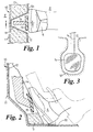
- a motor vehicle has a structural footwell 11 formed in part by a front bulkhead 10 separating a passenger compartment P from an engine compartment E.
- a driver operable brake pedal located in the footwell, comprises an arm 14 pivotably connected at its upper end to part of the body structure of the motor vehicle 10 by pivot means (not shown) and a foot pad 15 attached to the lower or free end of the arm 14.
- the bulkhead 10 is joined at its lower end to a floor member 20 which forms the bottom of the footwell.
- a carpet 12 lines the footwell, overlying both the floor 20 and the bulkhead 10.
- a layer of shock absorbing foam material overlies the part of the bulkhead forming the footwell and forms a foot support 13. It extends from the floor 20 to a position well above the height of the foot pad 15.
- the foam support 13 has a trough or recess 16 into which both the arm 14 and the pad 15 can be accommodated when the brake pedal is fully depressed to the extreme limit of its travel.
- This recess is shaped so as to correspond closely to the shape of the pedal 14, 15. As shown in Figure 3, at its lower end the recess is just wider and longer than the foot pad 15, and higher up it is narrower so as to be just wider than the pedal arm 14.
- the support therefore extends beneath and to either side of the pedal, substantially surrounding it.
- the foam support 13 is of sufficient thickness that when the brake pedal reaches its extreme limit of travel during impact, the upper surface of the pad 15 and the foam support 13 are approximately level, forming a substantially co-planar surface. Therefore if the driver's foot is not centrally located on the foot pad 15 but overhangs one side of it, a side portion 5b of the foot 5 comes into contact with the carpet 12 overlying the foam support 13, which thereby helps to reduce twisting of the driver's ankle.
- the presence of the foam support 13 below the lower edge of the foot pad 15, i.e. under the heel of the foot 5, ensures that the heel, which generally overhangs the lower edge of the foot pad 15, cannot easily be pushed under the foot pad 15 to cause damage to the driver's ankle.
- the foot 5 contacts the carpet 12 overlying the foam support 13 before the arm 14 contacts the carpet overlying the bulkhead 11 the foot 5 is not suddenly brought into contact with an extremely high resistance to movement but rather contacts the foam support 13 and is subject to a cushioned resistance.
- the foam support 13 is shaped so as to fit more closely to the shape of the brake pedal 14, 15.
- the recess 16 comprises a narrow slot 16a for receiving the pedal arm 14, and a broader, shallower depression 16b at the lower end of the slot 16a for receiving the foot pad 15.
- the support 13 extends continuously across the full width of the footwell and has similar recesses for the accelerator and clutch pedals (not shown). It therefore provides support and cushioning for the driver's right foot whether it is on the accelerator pedal, or the brake pedal, or between the two at the time of impact.
- a raised section 22 is provided in the support 13 which forms a foot rest for the driver's left foot.
- the closer fitting of the recess 16 to the shape of the pedal in this embodiment means that there is more of the foam support material close to the pedal 14, 15. Therefore maximum support for the driver's foot can be provided even if the pedals are relatively close together.
- the formation of the foot rest 22 from the foam material, which can be moulded to the desired shape, makes the footrest and foot support simple to manufacture and also provides a level of cushioning of the driver's left foot if it is on the footrest during impact. Furthermore, as the foam support is shaped to fit in the footwell, it can be easily and accurately located relative to the pedals.
Landscapes
- Engineering & Computer Science (AREA)
- Mechanical Engineering (AREA)
- Transportation (AREA)
- Passenger Equipment (AREA)
- Mechanical Control Devices (AREA)
Abstract
A motor vehicle is disclosed having a foam pad 13 located in the
vacinity of a foot pedal 14, 15. The foam pad 13 has a recess into which the
pedal 14, 15 can be fully accommodated when it is fully depressed. The
thickness of the foam pad 13 is such that the upper surface of the foot pad
15 of the foot pedal is co-planar with the surface of the foam pad 13 when
the foot pedal is at its extreme of travel so that it may support a foot 5
applied to the foot pad 15.
Description
This invention relates to a motor vehicle and in particular to a safety
apparatus for a motor vehicle to reduce the severity of injury to the lower
leg of a driver of a motor vehicle involved in an accident.
It is known to provide a motor vehicle with one or more foot pedals to
operate such features as the brakes, clutch and fuel supply. It is a
particular problem with the brake pedal, that in a crash situation the driver
is normally pressing hard on the brake pedal to effect maximum braking of
the motor vehicle, and, if the driver does not place his foot evenly on the
pedal but applies it using one side of his foot, severe impact tends to result
in twisting of the ankle and may result in serious injury. The same problem
can occur with the other pedals, but is less likely as the driver is usually
operating only the brake on impact.
It is known from GB 2 179 898 to provide a vehicle in which the floor of
the driver's footwell beneath the foot pedals is covered with a layer of energy
absorbing material to support the driver's foot in the event of a frontal
impact. However it can be a problem with this type of system that the
energy absorbing layer needs to be very firm to be of use under the high
loads experienced in frontal impacts, and the problem of the driver's ankle
being twisted therefore remains.
According to the invention there is provided a motor vehicle having a
driver compartment including a footwell, a foot operable pedal located in the
footwell, and a structural member situated to the front of the pedal and
defining part of the footwell, and support means overlying the structural
member in the region of the pedal, wherein the support means defines a
recess into which the pedal can be received when at its extreme of travel so
that the support means around the recess can support a part of the driver's
foot which overhangs the pedal.
The foot pedal may include a foot pad and a pedal arm.
The support means is preferably of sufficient thickness to form a
substantially co-planar surface with the upper surface of the foot pad when
the pedal is at its extreme of travel.
The support means may be formed from a structural foam material, or
any other suitable energy absorbing material.
Preferably the support means extends below the pedal so as to provide
support for the heel of the driver's foot.
More preferably the recess is shaped so as to fit the pedal, such that
when the pedal is at its extreme of travel, the support means substantially
surrounds the pedal.
The recess may comprise a narrow slot for receiving the pedal arm and
a shallower depression for receiving the foot pad.
Preferably the vehicle comprises a further pedal and the support means
defines a further recess for receiving said further pedal when at its extreme
of travel.
Preferably the support means includes a raised portion forming a
footrest for the driver.
The invention will now be described by way of example with reference
to the accompanying drawing of which:-
With reference to the Figures 1 to 3, in a first embodiment of the
invention a motor vehicle has a structural footwell 11 formed in part by a
front bulkhead 10 separating a passenger compartment P from an engine
compartment E. A driver operable brake pedal, located in the footwell,
comprises an arm 14 pivotably connected at its upper end to part of the body
structure of the motor vehicle 10 by pivot means (not shown) and a foot pad
15 attached to the lower or free end of the arm 14.
The bulkhead 10 is joined at its lower end to a floor member 20 which
forms the bottom of the footwell. A carpet 12 lines the footwell, overlying
both the floor 20 and the bulkhead 10. A layer of shock absorbing foam
material overlies the part of the bulkhead forming the footwell and forms a
foot support 13. It extends from the floor 20 to a position well above the
height of the foot pad 15. The foam support 13 has a trough or recess 16
into which both the arm 14 and the pad 15 can be accommodated when the
brake pedal is fully depressed to the extreme limit of its travel. This recess
is shaped so as to correspond closely to the shape of the pedal 14, 15. As
shown in Figure 3, at its lower end the recess is just wider and longer than
the foot pad 15, and higher up it is narrower so as to be just wider than the
pedal arm 14. The support therefore extends beneath and to either side of
the pedal, substantially surrounding it.
Generally under normal operating loads the pedal will travel about 70
to 80 mm from its fully released position which is shown in broken lines in
Figure 2. Under abusive loads this rises to about 100mm. Under frontal
impact conditions when the load on the pedal increases significantly beyond
what the driver could voluntarily apply, the pedal travel increases further to
about 120 or 130mm, which is shown in solid lines in Figure 2.
The foam support 13 is of sufficient thickness that when the brake
pedal reaches its extreme limit of travel during impact, the upper surface of
the pad 15 and the foam support 13 are approximately level, forming a
substantially co-planar surface. Therefore if the driver's foot is not centrally
located on the foot pad 15 but overhangs one side of it, a side portion 5b of
the foot 5 comes into contact with the carpet 12 overlying the foam support
13, which thereby helps to reduce twisting of the driver's ankle. In addition,
the presence of the foam support 13 below the lower edge of the foot pad 15,
i.e. under the heel of the foot 5, ensures that the heel, which generally
overhangs the lower edge of the foot pad 15, cannot easily be pushed under
the foot pad 15 to cause damage to the driver's ankle.
Because the foot 5 contacts the carpet 12 overlying the foam support 13
before the arm 14 contacts the carpet overlying the bulkhead 11 the foot 5 is
not suddenly brought into contact with an extremely high resistance to
movement but rather contacts the foam support 13 and is subject to a
cushioned resistance.
Referring to Figures 4 and 5, in a second embodiment the foam support
13 is shaped so as to fit more closely to the shape of the brake pedal 14, 15.
The recess 16 comprises a narrow slot 16a for receiving the pedal arm 14,
and a broader, shallower depression 16b at the lower end of the slot 16a for
receiving the foot pad 15. The support 13 extends continuously across the
full width of the footwell and has similar recesses for the accelerator and
clutch pedals (not shown). It therefore provides support and cushioning for
the driver's right foot whether it is on the accelerator pedal, or the brake
pedal, or between the two at the time of impact. At the left hand edge of the
footwell, just to the left of the clutch pedal, a raised section 22 is provided in
the support 13 which forms a foot rest for the driver's left foot.
The closer fitting of the recess 16 to the shape of the pedal in this
embodiment means that there is more of the foam support material close to
the pedal 14, 15. Therefore maximum support for the driver's foot can be
provided even if the pedals are relatively close together. The formation of
the foot rest 22 from the foam material, which can be moulded to the desired
shape, makes the footrest and foot support simple to manufacture and also
provides a level of cushioning of the driver's left foot if it is on the footrest
during impact. Furthermore, as the foam support is shaped to fit in the
footwell, it can be easily and accurately located relative to the pedals.
Claims (10)
- A motor vehicle having a driver compartment including a footwell, a foot operable pedal (14) located in the footwell, a structural member (10) situated to the front of the pedal and defining part of the footwell, and support means (12, 13) overlying the structural member in the region of the pedal, characterized in that the support means (12, 13) defines a recess (16) into which the pedal (14) can be received when at its extreme of travel so that the support means around the recess can support a part of the driver's foot (5) which overhangs the pedal.
- A motor vehicle as claimed in claim 1 characterized in that the foot pedal includes a foot pad (15) and a pedal arm (14).
- A motor vehicle according to claim 2 characterized in that the support means (12, 13) is of sufficient thickness to form a substantially co-planar surface with the upper surface of the foot pad (15) when the pedal is at its extreme of travel.
- A motor vehicle as claimed in any foregoing claim characterized in that the support means (12, 13) is formed from a structural foam material.
- A motor vehicle as claimed in any foregoing claim characterized in that the support means (12, 13) extends below the pedal (14) so as to provide support for the heel of the driver's foot.
- A motor vehicle as claimed in claim 5 characterized in that the recess (16) is shaped so as to fit the pedal, such that when the pedal is at its extreme of travel, the support means (12, 13) substantially surrounds the pedal (14).
- A motor vehicle according to claim 2 characterized in that the recess (16) comprises a narrow slot (16a) for receiving the pedal arm (14) and a shallower depression (16b) for receiving the foot pad (15).
- A motor vehicle according to any foregoing claim characterized in that it comprises a further pedal wherein the support means (12, 13) defines a further recess for receiving said further pedal when at its extreme of travel.
- A motor vehicle according to claim 8 characterized in that the support means (12, 13) extends continuously between the recesses for the two pedals.
- A motor vehicle according to any foregoing claim characterized in that said foot operable pedal (14) is a brake pedal.
Priority Applications (1)
| Application Number | Priority Date | Filing Date | Title |
|---|---|---|---|
| EP00301635A EP1129896A1 (en) | 2000-02-29 | 2000-02-29 | A motor vehicle safety apparatus |
Applications Claiming Priority (1)
| Application Number | Priority Date | Filing Date | Title |
|---|---|---|---|
| EP00301635A EP1129896A1 (en) | 2000-02-29 | 2000-02-29 | A motor vehicle safety apparatus |
Publications (1)
| Publication Number | Publication Date |
|---|---|
| EP1129896A1 true EP1129896A1 (en) | 2001-09-05 |
Family
ID=8172753
Family Applications (1)
| Application Number | Title | Priority Date | Filing Date |
|---|---|---|---|
| EP00301635A Withdrawn EP1129896A1 (en) | 2000-02-29 | 2000-02-29 | A motor vehicle safety apparatus |
Country Status (1)
| Country | Link |
|---|---|
| EP (1) | EP1129896A1 (en) |
Cited By (2)
| Publication number | Priority date | Publication date | Assignee | Title |
|---|---|---|---|---|
| FR2892534A1 (en) * | 2005-10-25 | 2007-04-27 | Renault Sas | VEHICLE PEDAL COMPRISING A PEDAL CONNECTED TO A FLOOR OF THE VEHICLE |
| WO2017144800A1 (en) * | 2016-02-26 | 2017-08-31 | Psa Automobiles S.A. | Pedal box for a motor vehicle |
Citations (4)
| Publication number | Priority date | Publication date | Assignee | Title |
|---|---|---|---|---|
| US2761329A (en) * | 1954-10-22 | 1956-09-04 | Eugene B Reed | Resiliently supported heel rest |
| GB2179898A (en) * | 1985-09-06 | 1987-03-18 | Daimler Benz Ag | Energy-absorbing foot-rest for vehicles |
| DE4335511A1 (en) * | 1992-10-29 | 1994-05-05 | Volkswagen Ag | Safety arrangement for driver of vehicle - has brake or clutch pedal mounted to swivel into recess in event of frontal crash |
| EP0798160A1 (en) * | 1996-03-29 | 1997-10-01 | Regie Nationale Des Usines Renault | Footrest covering for motor vehicle floor mats |
-
2000
- 2000-02-29 EP EP00301635A patent/EP1129896A1/en not_active Withdrawn
Patent Citations (4)
| Publication number | Priority date | Publication date | Assignee | Title |
|---|---|---|---|---|
| US2761329A (en) * | 1954-10-22 | 1956-09-04 | Eugene B Reed | Resiliently supported heel rest |
| GB2179898A (en) * | 1985-09-06 | 1987-03-18 | Daimler Benz Ag | Energy-absorbing foot-rest for vehicles |
| DE4335511A1 (en) * | 1992-10-29 | 1994-05-05 | Volkswagen Ag | Safety arrangement for driver of vehicle - has brake or clutch pedal mounted to swivel into recess in event of frontal crash |
| EP0798160A1 (en) * | 1996-03-29 | 1997-10-01 | Regie Nationale Des Usines Renault | Footrest covering for motor vehicle floor mats |
Cited By (5)
| Publication number | Priority date | Publication date | Assignee | Title |
|---|---|---|---|---|
| FR2892534A1 (en) * | 2005-10-25 | 2007-04-27 | Renault Sas | VEHICLE PEDAL COMPRISING A PEDAL CONNECTED TO A FLOOR OF THE VEHICLE |
| WO2017144800A1 (en) * | 2016-02-26 | 2017-08-31 | Psa Automobiles S.A. | Pedal box for a motor vehicle |
| FR3048213A1 (en) * | 2016-02-26 | 2017-09-01 | Peugeot Citroen Automobiles Sa | PEDAL FOR MOTOR VEHICLE |
| CN108698572A (en) * | 2016-02-26 | 2018-10-23 | 标致雪铁龙汽车股份有限公司 | Pedal box for motor vehicles |
| CN108698572B (en) * | 2016-02-26 | 2021-07-20 | 标致雪铁龙汽车股份有限公司 | Pedal box for motor vehicle |
Similar Documents
| Publication | Publication Date | Title |
|---|---|---|
| US6179079B1 (en) | Motor vehicle safety apparatus | |
| US4726438A (en) | Energy absorbing foot rest arrangement | |
| CN1292951C (en) | Vehicle floor panel | |
| EP0999118B1 (en) | Secondary floor assembly for a motor vehicle | |
| JP2011201510A (en) | Vehicle floor panel structure | |
| JP3808163B2 (en) | Automotive footrest | |
| JP2011243165A (en) | Operation pedal mounting structure for vehicle | |
| US20030084744A1 (en) | Adjustable assembly | |
| JP2002331895A (en) | Car body structure | |
| JP3619054B2 (en) | Car cabin floor structure | |
| US9090161B2 (en) | Structure of vehicle operation pedal | |
| JP7626591B2 (en) | Vehicle seat | |
| US2910888A (en) | Vehicle footrest pedal attachment | |
| JP3778704B2 (en) | Floor structure under the pedals for vehicles | |
| EP0913305A1 (en) | Vehicle foot pedals | |
| JP2011204193A (en) | Pedal device for vehicle | |
| US11130433B2 (en) | Floor structure | |
| JP2002308075A (en) | Arranging structure of accelerator pedal and brake pedal of vehicle and floor mat corresponding to this structure | |
| JPH10305753A (en) | Vehicle pedal system | |
| JP5832011B2 (en) | Vehicle footrest | |
| KR0120103Y1 (en) | Footrest structure of car with adjustable angle and height | |
| JP3518507B2 (en) | floor mat | |
| KR19980067872U (en) | Car Mat | |
| JP6938088B2 (en) | Vehicle pedals | |
| KR20090011197A (en) | Auxiliary pad for automobile brake pedal |
Legal Events
| Date | Code | Title | Description |
|---|---|---|---|
| PUAI | Public reference made under article 153(3) epc to a published international application that has entered the european phase |
Free format text: ORIGINAL CODE: 0009012 |
|
| AK | Designated contracting states |
Kind code of ref document: A1 Designated state(s): AT BE CH CY DE DK ES FI FR GB GR IE IT LI LU MC NL PT SE |
|
| AX | Request for extension of the european patent |
Free format text: AL;LT;LV;MK;RO;SI |
|
| AKX | Designation fees paid | ||
| REG | Reference to a national code |
Ref country code: DE Ref legal event code: 8566 |
|
| STAA | Information on the status of an ep patent application or granted ep patent |
Free format text: STATUS: THE APPLICATION IS DEEMED TO BE WITHDRAWN |
|
| 18D | Application deemed to be withdrawn |
Effective date: 20020306 |