EP1128576A1 - Antenna reception diversity in wireless communications - Google Patents
Antenna reception diversity in wireless communications Download PDFInfo
- Publication number
- EP1128576A1 EP1128576A1 EP01200714A EP01200714A EP1128576A1 EP 1128576 A1 EP1128576 A1 EP 1128576A1 EP 01200714 A EP01200714 A EP 01200714A EP 01200714 A EP01200714 A EP 01200714A EP 1128576 A1 EP1128576 A1 EP 1128576A1
- Authority
- EP
- European Patent Office
- Prior art keywords
- signals
- antenna signals
- produce
- received signal
- input
- Prior art date
- Legal status (The legal status is an assumption and is not a legal conclusion. Google has not performed a legal analysis and makes no representation as to the accuracy of the status listed.)
- Granted
Links
- 230000006854 communication Effects 0.000 title abstract description 25
- 238000004891 communication Methods 0.000 title abstract description 25
- 238000005562 fading Methods 0.000 claims abstract description 47
- 238000000034 method Methods 0.000 claims description 17
- 230000003111 delayed effect Effects 0.000 claims description 4
- 230000008878 coupling Effects 0.000 claims description 2
- 238000010168 coupling process Methods 0.000 claims description 2
- 238000005859 coupling reaction Methods 0.000 claims description 2
- 238000012935 Averaging Methods 0.000 claims 1
- 238000001228 spectrum Methods 0.000 description 4
- 238000007796 conventional method Methods 0.000 description 3
- 238000005516 engineering process Methods 0.000 description 2
- 230000006855 networking Effects 0.000 description 2
- 238000004088 simulation Methods 0.000 description 2
- 235000008694 Humulus lupulus Nutrition 0.000 description 1
- 230000007175 bidirectional communication Effects 0.000 description 1
- 230000005540 biological transmission Effects 0.000 description 1
- 239000003990 capacitor Substances 0.000 description 1
- 238000012937 correction Methods 0.000 description 1
- 238000005265 energy consumption Methods 0.000 description 1
- 230000000977 initiatory effect Effects 0.000 description 1
- 238000012986 modification Methods 0.000 description 1
- 230000004048 modification Effects 0.000 description 1
- 230000002093 peripheral effect Effects 0.000 description 1
- 230000001360 synchronised effect Effects 0.000 description 1
- 238000012549 training Methods 0.000 description 1
- 238000012546 transfer Methods 0.000 description 1
Images


Classifications
-
- H—ELECTRICITY
- H04—ELECTRIC COMMUNICATION TECHNIQUE
- H04B—TRANSMISSION
- H04B7/00—Radio transmission systems, i.e. using radiation field
- H04B7/02—Diversity systems; Multi-antenna system, i.e. transmission or reception using multiple antennas
- H04B7/04—Diversity systems; Multi-antenna system, i.e. transmission or reception using multiple antennas using two or more spaced independent antennas
- H04B7/08—Diversity systems; Multi-antenna system, i.e. transmission or reception using multiple antennas using two or more spaced independent antennas at the receiving station
- H04B7/0837—Diversity systems; Multi-antenna system, i.e. transmission or reception using multiple antennas using two or more spaced independent antennas at the receiving station using pre-detection combining
Definitions
- the invention relates generally to wireless communications and, more particularly, to antenna reception diversity in wireless communications.
- Dutta-Roy discusses several communication protocols in the 2.4 GHz band, including IEEE 802.11 direct-sequence spread spectrum (DSSS) and frequency-hopping (FHSS) protocols.
- DSSS direct-sequence spread spectrum
- FHSS frequency-hopping
- a disadvantage of these protocols is the high overhead associated with their implementation.
- a less complex wireless protocol known as Shared Wireless Access Protocol (SWAP) also operates in the 2.4 GHz band. This protocol has been developed by the HomeRF Working Group and is supported by North American communications companies.
- SWAP Shared Wireless Access Protocol
- the SWAP protocol uses frequency-hopping spread spectrum technology to produce a data rate of 1 Mb/sec.
- Another less complex protocol is named Bluetooth after a 10th century Scandinavian king who united several Danish kingdoms. This protocol also operates in the 2.4 GHz band and advantageously offers short-range wireless communication between Bluetooth devices without the need for a central network.
- the Bluetooth protocol provides a 1 Mb/sec data rate with low energy consumption for battery powered devices operating in the 2.4 GHz ISM (industrial, scientific, medical) band.
- the current Bluetooth protocol provides a 10-meter range and a maximum asymmetric data transfer rate of 723 kb/sec.
- the protocol supports a maximum of three voice channels for synchronous, CVSD-encoded transmission at 64 kb/sec.
- the Bluetooth protocol treats all radios as peer units except for a unique 48-bit address.
- the initiating unit is a temporary master. This temporary assignment, however, may change after initial communications are established. Each master may have active connections of up to seven slaves.
- Bluetooth master devices include cordless phone base stations, local area network (LAN) access points, laptop computers, or bridges to other networks.
- Bluetooth slave devices may include cordless handsets, cell phones, headsets, personal digital assistants, digital cameras, or computer peripherals such as printers, scanners, fax machines and other devices.
- the Bluetooth protocol uses time-division duplex (TDD) to support bi-directional communication.
- Frequency hopping permits operation in noisy environments and permits multiple piconets to exist in close proximity.
- the frequency hopping scheme permits up to 1600 hops per second over 79 1-MHZ channels or the entire 2.4 GHz ISM spectrum.
- error correcting schemes permit data packet protection by 1/3 and 2/3 rate forward error correction.
- Bluetooth uses retransmission of packets for guaranteed reliability. These schemes help correct data errors, but at the expense of throughput.
- the Bluetooth protocol is specified in detail in Specification of the Bluetooth System, Version 1.0A, July 26, 1999, which is incorporated herein by reference.
- Antenna reception diversity techniques are conventionally used to overcome fading in wireless communications. With antenna reception diversity, a communication signal is received by a plurality of antennas, and the associated antenna signals are then suitably combined to produce the desired communication signal for the receiver. Antenna reception diversity techniques can therefore improve communication quality in the presence of fading.
- the present invention provides antenna reception diversity wherein the received signal can be produced by combining the antenna signals with their associated fading amplitudes as estimated by a linear receiver. Also according to the invention, the antenna signals can be combined with their associated correlation values in place of estimated fading amplitudes. Further according to the invention, inherent characteristics of the receiver can be exploited such that the received signal is produced without any additional overhead that would otherwise be needed to provide estimated fading amplitudes.
- FIGURE 1 diagrammatically illustrates pertinent portions of a conventional non-linear wireless communication receiver, for example a Bluetooth receiver.
- the signal for example a Bluetooth FSK (frequency shift keying) signal
- IF intermediate frequency
- LPF low pass filter
- FIGURE 2 illustrates the discriminator 13 of FIGURE 1 in more detail.
- the discriminator 13 is implemented as a delay and multiply circuit which multiplies the limiter output signal by a delayed version of the limiter output signal (see also FIGURE 1).
- Optimal antenna selection diversity can be achieved by combining the radio frequency (RF) signals (received by a plurality of antennas) after the IF filter 11 and before the limiter 12.
- RF radio frequency
- a linear receiver can be inserted after the IF filter 11 as illustrated generally in the exemplary embodiment of FIGURE 3. All receiver examples described herein assume the use of N antennas and N corresponding RF front ends.
- FIGURE 3 illustrates at 31 N antenna signals which have been received from N separate antennas and have each passed through an associated IF filter such as shown at 11 in the non-linear receiver of FIGURE 1.
- the signals at 31 are input to a conventional N-channel linear receiver (or N linear receivers) 32.
- the linear receiver 32 can use conventional techniques to estimate fading amplitudes associated with each of the N antennas.
- the linear receiver can use conventional techniques to estimate fading amplitudes from training symbols, for example the symbols of the Bluetooth synchronization word.
- the fading amplitudes for each antenna signal are output from the linear receiver 32 to an averager 35 which can average the estimated fading amplitudes associated with each of the antenna signals, and thereby can output N average estimated fading amplitudes.
- These average estimated fading amplitudes are designated as ⁇ i in FIGURE 3.
- These average estimated fading amplitudes are input to a combiner 36 along with N corresponding antenna signals v i produced by N associated non-linear receivers such as the one shown in FIGURE 1.
- the combiner 36 combines ⁇ i and v i as follows in order to produce the received signal r.
- the signals v i are thus ratiometrically combined with respect to the squares of the signals ⁇ i .
- * ⁇ i * 2 is replaced in Equation 1 by * ⁇ i *.
- FIGURE 4 diagrammatically illustrates pertinent portions of another embodiment of a wireless communication receiver according to the invention.
- N antenna signals which have each passed through an associated IF filter 11, limiter 12 and discriminator 13 as illustrated in FIGURE 1, are input to a bank of N low pass filters 41.
- the signals output from the filters 41 can be input to a conventional thresholder 43, and are also input to a combiner 42. These signals are designated as v1 i in FIGURE 4.
- the thresholder 43 can be omitted in some embodiments, as shown by broken line.
- the signals output from the thresholder 43 are applied to a conventional correlator 44 which can use conventional techniques to correlate with any known part of the received signals. In a Bluetooth example, the correlator 44 can correlate with the Bluetooth synchronization word.
- the correlator can correlate with a larger part of the received signal, for example a packet header, in situations when the header is fixed (i.e., known).
- the maximum value of the correlation for each antenna signal is output from the correlator 44 to the combiner 42.
- These maximum values designated as ⁇ 1 i in FIGURE 4, can be used as an estimate of the fading amplitude.
- the combiner 42 combines the signals v1 i and ⁇ 1 i as follows to produce the received signal rl.
- the signals v1 i are thus ratiometrically combined with respect to the squares of the signals ⁇ 1 i .
- * ⁇ i 1* 2 is replaced in Equation 2 by * ⁇ i 1*.
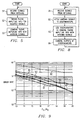
- FIGURE 5 illustrates exemplary operations which can be performed by the receivers of FIGURES 3 and 4.
- the signals from the antennas are received at 51, and the corresponding fading amplitude information is obtained at 52. Thereafter at 53, the fading amplitude information is combined with the antenna signals (e.g., using Equation 1 or 2) to produce the received signal.
- the present invention recognizes that, if the limiter 12 is removed from the conventional receiver of FIGURE 1, it can be shown analytically that the output of the delay and multiply discriminator 13 (see also FIGURE 2) has already been multiplied by the square of the fading amplitude associated with that antenna.
- the exemplary receiver of FIGURE 6 exploits this characteristic by coupling the output of the IF filter bank 61 directly to a bank of delay and multiply discriminators (or an N-channel discriminator) at 62.
- the discriminator outputs are applied to an LP filter bank 63, and the resulting LP-filtered signals, designated as v2 i in FIGURE 6, are applied to a combiner 64.
- the combiner combines the v2 i signals as follows to produce the received signal r2.
- the discriminator outputs in FIGURE 6 are already multiplied by the square of the corresponding fading amplitude, there is no need to estimate the fading amplitudes in the embodiment of FIGURE 6.
- the multipliers (or N-channel multiplier) at 65 of FIGURE 6 need to be real number multipliers, which can be relatively complex to implement.
- FIGURE 7 diagrammatically illustrates pertinent portions of an exemplary embodiment of a wireless communication receiver (e.g., a Bluetooth receiver) which exploits the aforementioned fading amplitude multiplication property of a delay and multiply discriminator, and which also avoids the necessity of implementing a real number multiplier.
- the embodiment of FIGURE 7 is generally similar to the embodiment of FIGURE 6, except that limiters (or an N-channel limiter) 71 are inserted into the delay and multiply discriminators between the IF filters 61 and the delay elements (or N-channel delay element) 66.
- the multiplier 65A is just a real number adder, which is easily implemented, for example, using charge/discharge capacitors.
- a combiner 72 combines the outputs v3 i of the LP filters 63 as follows to produce the received signal r3.
- FIGURE 8 illustrates exemplary operations which can be performed by the receivers of FIGURES 6 and 7.
- the antenna signals are received at 81, and are applied to delay and multiply discriminators at 82.
- the fading amplitude multiplication characteristic of the discriminators is exploited to combine the antenna signals with the corresponding fading amplitude information.
- the discriminator outputs are combined, for example, according to Equation 4.
- the curve 92 is obtained using one antenna
- the curve 93 is obtained using two selectively switched antennas which share a common RF front end.
- the curve 94 corresponds to the receiver of FIGURE 3
- the curve 95 corresponds to the receiver of FIGURE 4
- the curve 96 corresponds to the receiver of FIGURE 7.
- FIGURES 2-8 can be implemented, for example, by suitable modifications in software, hardware, or a combination of software and hardware, in conventional radio receivers that use antenna reception diversity, for example Bluetooth receivers.
Landscapes
- Engineering & Computer Science (AREA)
- Computer Networks & Wireless Communication (AREA)
- Signal Processing (AREA)
- Radio Transmission System (AREA)
- Mobile Radio Communication Systems (AREA)
- Details Of Aerials (AREA)
Abstract
Description
- The invention relates generally to wireless communications and, more particularly, to antenna reception diversity in wireless communications.
- Present telecommunication system technology includes a wide variety of wireless networking systems associated with both voice and data communications. An overview of several of these wireless networking systems is presented by Amitava Dutta-Roy, Communications. Networks for Homes, IEEE Spectrum, pg. 26, Dec. 1999. Therein, Dutta-Roy discusses several communication protocols in the 2.4 GHz band, including IEEE 802.11 direct-sequence spread spectrum (DSSS) and frequency-hopping (FHSS) protocols. A disadvantage of these protocols is the high overhead associated with their implementation. A less complex wireless protocol known as Shared Wireless Access Protocol (SWAP) also operates in the 2.4 GHz band. This protocol has been developed by the HomeRF Working Group and is supported by North American communications companies. The SWAP protocol uses frequency-hopping spread spectrum technology to produce a data rate of 1 Mb/sec. Another less complex protocol is named Bluetooth after a 10th century Scandinavian king who united several Danish kingdoms. This protocol also operates in the 2.4 GHz band and advantageously offers short-range wireless communication between Bluetooth devices without the need for a central network.
- The Bluetooth protocol provides a 1 Mb/sec data rate with low energy consumption for battery powered devices operating in the 2.4 GHz ISM (industrial, scientific, medical) band. The current Bluetooth protocol provides a 10-meter range and a maximum asymmetric data transfer rate of 723 kb/sec. The protocol supports a maximum of three voice channels for synchronous, CVSD-encoded transmission at 64 kb/sec. The Bluetooth protocol treats all radios as peer units except for a unique 48-bit address. At the start of any connection, the initiating unit is a temporary master. This temporary assignment, however, may change after initial communications are established. Each master may have active connections of up to seven slaves. Such a connection between a master and one or more slaves forms a "piconet." Link management allows communication between piconets, thereby forming "scatternets." Typical Bluetooth master devices include cordless phone base stations, local area network (LAN) access points, laptop computers, or bridges to other networks. Bluetooth slave devices may include cordless handsets, cell phones, headsets, personal digital assistants, digital cameras, or computer peripherals such as printers, scanners, fax machines and other devices.
- The Bluetooth protocol uses time-division duplex (TDD) to support bi-directional communication. Frequency hopping permits operation in noisy environments and permits multiple piconets to exist in close proximity. The frequency hopping scheme permits up to 1600 hops per second over 79 1-MHZ channels or the entire 2.4 GHz ISM spectrum. Various error correcting schemes permit data packet protection by 1/3 and 2/3 rate forward error correction. Further, Bluetooth uses retransmission of packets for guaranteed reliability. These schemes help correct data errors, but at the expense of throughput.
- The Bluetooth protocol is specified in detail in Specification of the Bluetooth System, Version 1.0A, July 26, 1999, which is incorporated herein by reference.
- Fading is a well known problem in wireless communications systems such as Bluetooth systems. Antenna reception diversity techniques are conventionally used to overcome fading in wireless communications. With antenna reception diversity, a communication signal is received by a plurality of antennas, and the associated antenna signals are then suitably combined to produce the desired communication signal for the receiver. Antenna reception diversity techniques can therefore improve communication quality in the presence of fading.
- It is therefore desirable to provide for improved antenna reception diversity in wireless communications systems such as Bluetooth systems.
- The present invention provides antenna reception diversity wherein the received signal can be produced by combining the antenna signals with their associated fading amplitudes as estimated by a linear receiver. Also according to the invention, the antenna signals can be combined with their associated correlation values in place of estimated fading amplitudes. Further according to the invention, inherent characteristics of the receiver can be exploited such that the received signal is produced without any additional overhead that would otherwise be needed to provide estimated fading amplitudes.
- The present invention will now be further described, by way of example, with reference to the preferred and exemplary embodiments illustrated in the figures of the accompanying drawings in which:
- FIGURES 1 and 2 diagrammatically illustrate pertinent portions of a conventional Bluetooth receiver.
- FIGURE 3 diagrammatically illustrates pertinent portions of an exemplary embodiment of a wireless communication receiver.
- FIGURE 4 diagrammatically illustrates pertinent portions of a further exemplary embodiment of a wireless communication receiver.
- FIGURE 5 illustrates exemplary operations which can be performed by the receivers of FIGURES 3 and 4.
- FIGURE 6 diagrammatically illustrates pertinent portions of a further exemplary embodiment of a wireless communication receiver.
- FIGURE 7 diagrammatically illustrates pertinent portions of a further exemplary embodiment of a wireless communication receiver.
- FIGURE 8 illustrates exemplary operations which can be performed by the receivers of FIGURES 6 and 7, and
- FIGURE 9 illustrates simulation results obtained according to the invention.
-
- FIGURE 1 diagrammatically illustrates pertinent portions of a conventional non-linear wireless communication receiver, for example a Bluetooth receiver. As illustrated in FIGURE 1, the signal, for example a Bluetooth FSK (frequency shift keying) signal, from a given antenna is input to an intermediate frequency (IF)
filter 11, and the resulting filtered signal is input to alimiter 12. The output of the limiter is applied to adiscriminator 13, whose output is coupled to a low pass filter (LPF) 14. - FIGURE 2 illustrates the
discriminator 13 of FIGURE 1 in more detail. In the example of FIGURE 2, thediscriminator 13 is implemented as a delay and multiply circuit which multiplies the limiter output signal by a delayed version of the limiter output signal (see also FIGURE 1). - Optimal antenna selection diversity according to the invention can be achieved by combining the radio frequency (RF) signals (received by a plurality of antennas) after the IF filter 11 and before the
limiter 12. According to one exemplary embodiment of the invention, a linear receiver can be inserted after theIF filter 11 as illustrated generally in the exemplary embodiment of FIGURE 3. All receiver examples described herein assume the use of N antennas and N corresponding RF front ends. - The example of FIGURE 3 (taken in conjunction with FIGURE 1) illustrates at 31 N antenna signals which have been received from N separate antennas and have each passed through an associated IF filter such as shown at 11 in the non-linear receiver of FIGURE 1. The signals at 31 are input to a conventional N-channel linear receiver (or N linear receivers) 32. The
linear receiver 32 can use conventional techniques to estimate fading amplitudes associated with each of the N antennas. For each of the N antenna signals at 31, the linear receiver can use conventional techniques to estimate fading amplitudes from training symbols, for example the symbols of the Bluetooth synchronization word. The fading amplitudes for each antenna signal are output from thelinear receiver 32 to anaverager 35 which can average the estimated fading amplitudes associated with each of the antenna signals, and thereby can output N average estimated fading amplitudes. These average estimated fading amplitudes are designated as αi in FIGURE 3. These average estimated fading amplitudes are input to acombiner 36 along with N corresponding antenna signals vi produced by N associated non-linear receivers such as the one shown in FIGURE 1. Thecombiner 36 combines αi and vi as followsin order to produce the received signal r. The signals vi are thus ratiometrically combined with respect to the squares of the signals αi. In some embodiments, *αi*2 is replaced in Equation 1 by *αi*.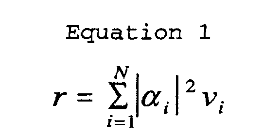
- FIGURE 4 diagrammatically illustrates pertinent portions of another embodiment of a wireless communication receiver according to the invention. In the receiver of FIGURE 4, N antenna signals which have each passed through an associated IF
filter 11,limiter 12 anddiscriminator 13 as illustrated in FIGURE 1, are input to a bank of N low pass filters 41. The signals output from thefilters 41 can be input to aconventional thresholder 43, and are also input to acombiner 42. These signals are designated as v1i in FIGURE 4. Thethresholder 43 can be omitted in some embodiments, as shown by broken line. The signals output from thethresholder 43 are applied to aconventional correlator 44 which can use conventional techniques to correlate with any known part of the received signals. In a Bluetooth example, thecorrelator 44 can correlate with the Bluetooth synchronization word. As another example, the correlator can correlate with a larger part of the received signal, for example a packet header, in situations when the header is fixed (i.e., known). The maximum value of the correlation for each antenna signal is output from thecorrelator 44 to thecombiner 42. These maximum values, designated as α1i in FIGURE 4, can be used as an estimate of the fading amplitude. Thecombiner 42 combines the signals v1i and α1i as followsto produce the received signal rl. The signals v1i are thus ratiometrically combined with respect to the squares of the signals α1i. In some embodiments, *αi1*2 is replaced in Equation 2 by *αi1*.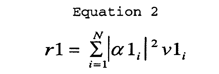
- FIGURE 5 illustrates exemplary operations which can be performed by the receivers of FIGURES 3 and 4. The signals from the antennas are received at 51, and the corresponding fading amplitude information is obtained at 52. Thereafter at 53, the fading amplitude information is combined with the antenna signals (e.g., using Equation 1 or 2) to produce the received signal.
- The present invention recognizes that, if the
limiter 12 is removed from the conventional receiver of FIGURE 1, it can be shown analytically that the output of the delay and multiply discriminator 13 (see also FIGURE 2) has already been multiplied by the square of the fading amplitude associated with that antenna. The exemplary receiver of FIGURE 6 exploits this characteristic by coupling the output of theIF filter bank 61 directly to a bank of delay and multiply discriminators (or an N-channel discriminator) at 62. The discriminator outputs are applied to anLP filter bank 63, and the resulting LP-filtered signals, designated as v2i in FIGURE 6, are applied to acombiner 64. The combiner combines the v2i signals as followsto produce the received signal r2. Because the discriminator outputs in FIGURE 6 are already multiplied by the square of the corresponding fading amplitude, there is no need to estimate the fading amplitudes in the embodiment of FIGURE 6. However, the multipliers (or N-channel multiplier) at 65 of FIGURE 6 need to be real number multipliers, which can be relatively complex to implement.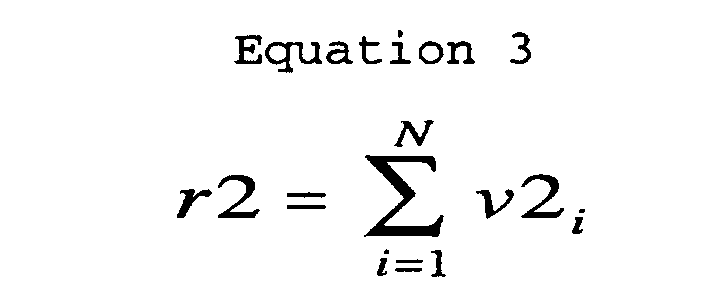
- FIGURE 7 diagrammatically illustrates pertinent portions of an exemplary embodiment of a wireless communication receiver (e.g., a Bluetooth receiver) which exploits the aforementioned fading amplitude multiplication property of a delay and multiply discriminator, and which also avoids the necessity of implementing a real number multiplier. The embodiment of FIGURE 7 is generally similar to the embodiment of FIGURE 6, except that limiters (or an N-channel limiter) 71 are inserted into the delay and multiply discriminators between the IF filters 61 and the delay elements (or N-channel delay element) 66. With this arrangement, the
multiplier 65A is just a real number adder, which is easily implemented, for example, using charge/discharge capacitors. Acombiner 72 combines the outputs v3i of the LP filters 63 as followsto produce the received signal r3.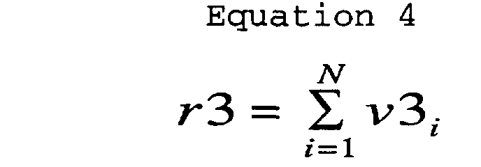
- FIGURE 8 illustrates exemplary operations which can be performed by the receivers of FIGURES 6 and 7. The antenna signals are received at 81, and are applied to delay and multiply discriminators at 82. At 83, the fading amplitude multiplication characteristic of the discriminators is exploited to combine the antenna signals with the corresponding fading amplitude information. Thereafter at 84, the discriminator outputs are combined, for example, according to Equation 4.
- FIGURE 9 illustrates exemplary simulation results associated with the receivers of FIGURES 3, 4 and 7 with N = 2 antennas. In FIGURE 9, the
curve 91 is optimum reception diversity with N = 2 antennas, thecurve 92 is obtained using one antenna, and thecurve 93 is obtained using two selectively switched antennas which share a common RF front end. Thecurve 94 corresponds to the receiver of FIGURE 3, thecurve 95 corresponds to the receiver of FIGURE 4 and thecurve 96 corresponds to the receiver of FIGURE 7. - It will be evident to workers in the art that the embodiments described above with respect to FIGURES 2-8 can be implemented, for example, by suitable modifications in software, hardware, or a combination of software and hardware, in conventional radio receivers that use antenna reception diversity, for example Bluetooth receivers.
Claims (22)
- A method of producing a received signal from a plurality of antenna signals respectively produced from a plurality of antennas by a non-linear receiver, which method comprising:using a linear receiver to estimate fading amplitudes associated with the respective antenna signals; andcombining the estimated fading amplitudes with the associated antenna signals to produce the received signal.
- A method of producing a received signal from a plurality of antenna signals respectively produced from a plurality of antennas by a non-linear receiver, which method comprising:using a correlator to estimate fading amplitudes associated with the respective antenna signals; andcombining the estimated fading amplitudes with the associated antenna signals to produce the received signal.
- The method of Claim 1 or 2, wherein said combining step includes combining the antenna signals ratiometrically with respect to the associated fading amplitude estimates.
- The method of Claim 3, wherein said combining step includes multiplying squares of the estimated fading amplitudes by the associated antenna signals to produce a plurality of combined signals, and summing the combined signals to produce the received signal.
- The method of Claim 3, wherein said combining step includes multiplying the estimated fading amplitudes by the associated antenna signals to produce a plurality of combined signals, and summing the combined signals to produce the received signal.
- The method of Claim 2, wherein said using step includes determining correlation values for the respective antenna signals and providing the correlation values as the estimated fading amplitudes.
- A method of producing a received signal from a plurality of antenna signals respectively associated with a plurality of antennas, which method comprising:multiplying the antenna signals by respectively delayed versions of the antenna signals to thereby produce further signals that represent the antenna signals combined with their associated fading amplitudes; andcombining the further signals to produce the received signal.
- The method of Claim 7, including passing each of the antenna signals through a limiter and a delay element to produce the delayed versions of the antenna signals.
- The method of Claim 7 or 8, wherein said combining step includes summing the further signals to produce the received signal.
- The method of any one of Claims 7-9, wherein the further signals represent squares of the fading amplitudes multiplied by the associated antenna signals.
- An apparatus for producing a received signal from a plurality of antenna signals respectively produced from a plurality of antennas by a non-linear receiver, which method comprising:a combiner having a first input for receiving the antenna signals and a second input for receiving estimated fading amplitudes associated with the respective antenna signals, said combiner operable for combining the estimated fading amplitudes with the associated antenna signals to produce the received signal; anda linear receiver having an input for coupling to the antennas, said linear receiver operable in response to signals received from the antennas for producing at an output thereof information indicative of the estimated fading amplitudes, said linear receiver output coupled to said second input of said combiner.
- The apparatus of Claim 11, including an averager coupled between said linear receiver output and said second input of said combiner for averaging said information provided at said output to produce the estimated fading amplitudes.
- An apparatus for producing a received signal from a plurality of antenna signals respectively produced from a plurality of antennas by a non-linear receiver; which method comprising:a combiner having a first input for receiving the antenna signals and a second input for receiving estimated fading amplitudes associated with the respective antenna signals, said combiner operable for combining the estimated fading amplitudes with the associated antenna signals to produce the received signal; anda correlator having a third input coupled to said first input and responsive thereto for producing correlation values associated with the respective antenna signals, said correlator having an output coupled to said second input of said combiner for providing the correlation values to said combiner as the estimated fading amplitudes.
- The apparatus of Claim 13, including a thresholder coupled between said first input and said third input.
- The apparatus of Claim 11 or 13, wherein said combiner is operable for combining the antenna signals ratiometrically with respect to the associated fading amplitude estimates.
- The apparatus of Claim 15, wherein said combiner is further operable for multiplying squares of the estimated fading amplitudes by the associated antenna signals to produce a plurality of combined signals, and for summing the combined signals to produce the received signal.
- The apparatus of Claim 15, wherein said combiner is further operable for multiplying the estimated fading amplitudes by the associated antenna signals to produce a plurality of combined signals, and for summing the combined signals to produce the received signal.
- An apparatus for producing a received signal from a plurality of antenna signals respectively associated with a plurality of antennas, which apparatus comprising:a discriminator having a first input for receiving the antenna signals, said discriminator operable for multiplying the antenna signals by respectively delayed versions of the antenna signals to thereby produce further signals that represent the antenna signals combined with their associated fading amplitudes; anda combiner coupled to said discriminator for combining the further signals to produce the received signal.
- The apparatus of Claim 18, wherein said discriminator includes a multiplier having a second input coupled to said first input, said multiplier including a third input, and said discriminator further including a delay element coupled between said first input and said third input.
- The apparatus of Claim 19, wherein said discriminator further includes a limiter coupled between said first input and said delay element.
- The apparatus of Claim 18, wherein said combiner is operable for summing the further signals to produce the received signal.
- The apparatus of Claim 18, wherein the further signals represent squares of the fading amplitudes multiplied by the associated antenna signals.
Applications Claiming Priority (4)
| Application Number | Priority Date | Filing Date | Title |
|---|---|---|---|
| US18463400P | 2000-02-24 | 2000-02-24 | |
| US184634P | 2000-02-24 | ||
| US634052 | 2000-08-08 | ||
| US09/634,052 US6714774B1 (en) | 2000-02-24 | 2000-08-08 | Antenna reception diversity in wireless communications |
Publications (2)
| Publication Number | Publication Date |
|---|---|
| EP1128576A1 true EP1128576A1 (en) | 2001-08-29 |
| EP1128576B1 EP1128576B1 (en) | 2010-10-06 |
Family
ID=26880343
Family Applications (1)
| Application Number | Title | Priority Date | Filing Date |
|---|---|---|---|
| EP01200714A Expired - Lifetime EP1128576B1 (en) | 2000-02-24 | 2001-02-26 | Antenna reception diversity in wireless communications |
Country Status (4)
| Country | Link |
|---|---|
| US (1) | US6714774B1 (en) |
| EP (1) | EP1128576B1 (en) |
| AT (1) | ATE484112T1 (en) |
| DE (1) | DE60143173D1 (en) |
Families Citing this family (6)
| Publication number | Priority date | Publication date | Assignee | Title |
|---|---|---|---|---|
| US7035350B2 (en) * | 2001-10-22 | 2006-04-25 | Broadcom Corporation | Bluetooth access code assisted initial DC estimation and frame synchronization |
| US7231000B2 (en) * | 2001-10-22 | 2007-06-12 | Broadcom Corporation | System and method for DC offset compensation and bit synchronization |
| US7251466B2 (en) * | 2004-08-20 | 2007-07-31 | Xceive Corporation | Television receiver including an integrated band selection filter |
| US20080201078A1 (en) * | 2006-09-28 | 2008-08-21 | Dudley Fitzpatrick | Apparatuses, Methods and Systems for Determining and Announcing Proximity Between Trajectories |
| US8599824B2 (en) * | 2008-01-11 | 2013-12-03 | Broadcom Corporation | Method and system for bluetooth conditional synchronization |
| US11764857B2 (en) * | 2021-02-25 | 2023-09-19 | The Boeing Company | Systems and methods for multiple signal reception using receiver diversity |
Citations (3)
| Publication number | Priority date | Publication date | Assignee | Title |
|---|---|---|---|---|
| EP0687076A2 (en) * | 1994-06-07 | 1995-12-13 | Nec Corporation | Diversity communication system with arrays of antennas using adaptive mezched filters and decision feedback equalizers |
| US5778310A (en) * | 1995-11-30 | 1998-07-07 | Northern Telecom Limited | Co-channel interference reduction |
| US5838742A (en) | 1996-07-10 | 1998-11-17 | Northern Telecom Limited | Diversity path co-channel interference reduction |
Family Cites Families (7)
| Publication number | Priority date | Publication date | Assignee | Title |
|---|---|---|---|---|
| JP2982504B2 (en) * | 1992-07-31 | 1999-11-22 | 日本電気株式会社 | Adaptive receiver |
| JP2780576B2 (en) * | 1992-08-05 | 1998-07-30 | 日本電気株式会社 | Interference wave canceller |
| DE69327837T2 (en) * | 1992-12-01 | 2000-10-12 | Koninklijke Philips Electronics N.V., Eindhoven | Subband diversity transmission system |
| MY113061A (en) * | 1994-05-16 | 2001-11-30 | Sanyo Electric Co | Diversity reception device |
| SE503785C2 (en) * | 1994-12-12 | 1996-09-02 | Ericsson Telefon Ab L M | Method and apparatus for aggregating signals |
| US5930293A (en) * | 1997-03-10 | 1999-07-27 | Lucent Technologies Inc. | Method and apparatus for achieving antenna receive diversity with wireless repeaters |
| US6505053B1 (en) * | 1999-11-05 | 2003-01-07 | At&T Corp. | Method for sinusoidal modeling and prediction of fast fading processes |
-
2000
- 2000-08-08 US US09/634,052 patent/US6714774B1/en not_active Expired - Lifetime
-
2001
- 2001-02-26 AT AT01200714T patent/ATE484112T1/en not_active IP Right Cessation
- 2001-02-26 DE DE60143173T patent/DE60143173D1/en not_active Expired - Lifetime
- 2001-02-26 EP EP01200714A patent/EP1128576B1/en not_active Expired - Lifetime
Patent Citations (3)
| Publication number | Priority date | Publication date | Assignee | Title |
|---|---|---|---|---|
| EP0687076A2 (en) * | 1994-06-07 | 1995-12-13 | Nec Corporation | Diversity communication system with arrays of antennas using adaptive mezched filters and decision feedback equalizers |
| US5778310A (en) * | 1995-11-30 | 1998-07-07 | Northern Telecom Limited | Co-channel interference reduction |
| US5838742A (en) | 1996-07-10 | 1998-11-17 | Northern Telecom Limited | Diversity path co-channel interference reduction |
Also Published As
| Publication number | Publication date |
|---|---|
| EP1128576B1 (en) | 2010-10-06 |
| ATE484112T1 (en) | 2010-10-15 |
| US6714774B1 (en) | 2004-03-30 |
| DE60143173D1 (en) | 2010-11-18 |
Similar Documents
| Publication | Publication Date | Title |
|---|---|---|
| US6396457B1 (en) | Concentrator for coupling local wireless networks to a wired network | |
| EP1107475B1 (en) | Communication circuit and method of communicating | |
| EP1130858B1 (en) | Dynamic frequency selection in frequency hopping system for master-slave communication | |
| US7113745B2 (en) | Method to achieve diversity in a communication network | |
| EP1183813B1 (en) | Time and frequency diversity in fh/tdd systems | |
| US20060215611A1 (en) | Radio communication apparatus, radio communication method, communication channel assigning method and assigning apparatus | |
| US7684465B1 (en) | Frequency hopping communication protocol | |
| US20080117850A1 (en) | Dual Mode Wireless Personal Area Network and Wireless Local Area Network Architecture | |
| KR100843655B1 (en) | How to Retrieve Pilot Signals to Synchronize CDM Receivers and Associated Transmitters | |
| US6970495B1 (en) | Adjustment of slave frequency hopping pattern to improve channel measurement opportunities in wireless communications | |
| US6714774B1 (en) | Antenna reception diversity in wireless communications | |
| US6975684B1 (en) | Dynamic slave frequency selection for improving uplink frequency hopping wireless communications | |
| US6931051B2 (en) | Frequency hopping wireless communication system with filtered adaptive slicer | |
| US7088785B2 (en) | Block level space time transmit diversity in wireless communications | |
| TW202029662A (en) | Wireless communication apparatus and associated wireless communication method | |
| JP2011114636A (en) | Approximate synchronizing cdma communication system | |
| US7218680B1 (en) | Retransmission techniques for enhanced performance in fading wireless communication channels | |
| US6970440B1 (en) | Enhanced performance in frequency hopping wireless communications by combining frequency dwelling with data transmission adjustments | |
| US6973117B1 (en) | Dynamic extension of frequency hopping patterns in wireless communications | |
| JPH07327263A (en) | Mobile communication device | |
| Miyatsu | Bluetooth design background and its technological features | |
| WO2012050095A1 (en) | Communication device, communication system, and communication method | |
| Lee | Peer-to-peer wireless system |
Legal Events
| Date | Code | Title | Description |
|---|---|---|---|
| PUAI | Public reference made under article 153(3) epc to a published international application that has entered the european phase |
Free format text: ORIGINAL CODE: 0009012 |
|
| 17P | Request for examination filed |
Effective date: 20010226 |
|
| AK | Designated contracting states |
Kind code of ref document: A1 Designated state(s): AT BE CH CY DE DK ES FI FR GB GR IE IT LI LU MC NL PT SE TR |
|
| AX | Request for extension of the european patent |
Free format text: AL;LT;LV;MK;RO;SI |
|
| AKX | Designation fees paid |
Free format text: AT BE CH CY DE DK ES FI FR GB GR IE IT LI LU MC NL PT SE TR |
|
| 17Q | First examination report despatched |
Effective date: 20071221 |
|
| GRAP | Despatch of communication of intention to grant a patent |
Free format text: ORIGINAL CODE: EPIDOSNIGR1 |
|
| GRAS | Grant fee paid |
Free format text: ORIGINAL CODE: EPIDOSNIGR3 |
|
| GRAA | (expected) grant |
Free format text: ORIGINAL CODE: 0009210 |
|
| AK | Designated contracting states |
Kind code of ref document: B1 Designated state(s): AT BE CH CY DE DK ES FI FR GB GR IE IT LI LU MC NL PT SE TR |
|
| REG | Reference to a national code |
Ref country code: GB Ref legal event code: FG4D |
|
| REG | Reference to a national code |
Ref country code: CH Ref legal event code: EP |
|
| REG | Reference to a national code |
Ref country code: IE Ref legal event code: FG4D |
|
| REF | Corresponds to: |
Ref document number: 60143173 Country of ref document: DE Date of ref document: 20101118 Kind code of ref document: P |
|
| REG | Reference to a national code |
Ref country code: NL Ref legal event code: T3 |
|
| PG25 | Lapsed in a contracting state [announced via postgrant information from national office to epo] |
Ref country code: AT Free format text: LAPSE BECAUSE OF FAILURE TO SUBMIT A TRANSLATION OF THE DESCRIPTION OR TO PAY THE FEE WITHIN THE PRESCRIBED TIME-LIMIT Effective date: 20101006 Ref country code: SE Free format text: LAPSE BECAUSE OF FAILURE TO SUBMIT A TRANSLATION OF THE DESCRIPTION OR TO PAY THE FEE WITHIN THE PRESCRIBED TIME-LIMIT Effective date: 20101006 Ref country code: PT Free format text: LAPSE BECAUSE OF FAILURE TO SUBMIT A TRANSLATION OF THE DESCRIPTION OR TO PAY THE FEE WITHIN THE PRESCRIBED TIME-LIMIT Effective date: 20110207 Ref country code: FI Free format text: LAPSE BECAUSE OF FAILURE TO SUBMIT A TRANSLATION OF THE DESCRIPTION OR TO PAY THE FEE WITHIN THE PRESCRIBED TIME-LIMIT Effective date: 20101006 |
|
| PG25 | Lapsed in a contracting state [announced via postgrant information from national office to epo] |
Ref country code: BE Free format text: LAPSE BECAUSE OF FAILURE TO SUBMIT A TRANSLATION OF THE DESCRIPTION OR TO PAY THE FEE WITHIN THE PRESCRIBED TIME-LIMIT Effective date: 20101006 Ref country code: GR Free format text: LAPSE BECAUSE OF FAILURE TO SUBMIT A TRANSLATION OF THE DESCRIPTION OR TO PAY THE FEE WITHIN THE PRESCRIBED TIME-LIMIT Effective date: 20110107 |
|
| PG25 | Lapsed in a contracting state [announced via postgrant information from national office to epo] |
Ref country code: ES Free format text: LAPSE BECAUSE OF FAILURE TO SUBMIT A TRANSLATION OF THE DESCRIPTION OR TO PAY THE FEE WITHIN THE PRESCRIBED TIME-LIMIT Effective date: 20110117 |
|
| PLBE | No opposition filed within time limit |
Free format text: ORIGINAL CODE: 0009261 |
|
| STAA | Information on the status of an ep patent application or granted ep patent |
Free format text: STATUS: NO OPPOSITION FILED WITHIN TIME LIMIT |
|
| PG25 | Lapsed in a contracting state [announced via postgrant information from national office to epo] |
Ref country code: DK Free format text: LAPSE BECAUSE OF FAILURE TO SUBMIT A TRANSLATION OF THE DESCRIPTION OR TO PAY THE FEE WITHIN THE PRESCRIBED TIME-LIMIT Effective date: 20101006 |
|
| 26N | No opposition filed |
Effective date: 20110707 |
|
| PG25 | Lapsed in a contracting state [announced via postgrant information from national office to epo] |
Ref country code: MC Free format text: LAPSE BECAUSE OF NON-PAYMENT OF DUE FEES Effective date: 20110228 |
|
| REG | Reference to a national code |
Ref country code: CH Ref legal event code: PL |
|
| PG25 | Lapsed in a contracting state [announced via postgrant information from national office to epo] |
Ref country code: LI Free format text: LAPSE BECAUSE OF NON-PAYMENT OF DUE FEES Effective date: 20110228 Ref country code: CH Free format text: LAPSE BECAUSE OF NON-PAYMENT OF DUE FEES Effective date: 20110228 |
|
| REG | Reference to a national code |
Ref country code: DE Ref legal event code: R097 Ref document number: 60143173 Country of ref document: DE Effective date: 20110707 |
|
| REG | Reference to a national code |
Ref country code: DE Ref legal event code: R082 Ref document number: 60143173 Country of ref document: DE |
|
| PG25 | Lapsed in a contracting state [announced via postgrant information from national office to epo] |
Ref country code: IT Free format text: LAPSE BECAUSE OF FAILURE TO SUBMIT A TRANSLATION OF THE DESCRIPTION OR TO PAY THE FEE WITHIN THE PRESCRIBED TIME-LIMIT Effective date: 20101006 |
|
| PG25 | Lapsed in a contracting state [announced via postgrant information from national office to epo] |
Ref country code: CY Free format text: LAPSE BECAUSE OF FAILURE TO SUBMIT A TRANSLATION OF THE DESCRIPTION OR TO PAY THE FEE WITHIN THE PRESCRIBED TIME-LIMIT Effective date: 20101006 Ref country code: LU Free format text: LAPSE BECAUSE OF NON-PAYMENT OF DUE FEES Effective date: 20110226 |
|
| PG25 | Lapsed in a contracting state [announced via postgrant information from national office to epo] |
Ref country code: TR Free format text: LAPSE BECAUSE OF FAILURE TO SUBMIT A TRANSLATION OF THE DESCRIPTION OR TO PAY THE FEE WITHIN THE PRESCRIBED TIME-LIMIT Effective date: 20101006 |
|
| REG | Reference to a national code |
Ref country code: FR Ref legal event code: PLFP Year of fee payment: 16 |
|
| PGFP | Annual fee paid to national office [announced via postgrant information from national office to epo] |
Ref country code: DE Payment date: 20160302 Year of fee payment: 16 Ref country code: IE Payment date: 20160126 Year of fee payment: 16 |
|
| PGFP | Annual fee paid to national office [announced via postgrant information from national office to epo] |
Ref country code: NL Payment date: 20160205 Year of fee payment: 16 Ref country code: FR Payment date: 20160125 Year of fee payment: 16 Ref country code: GB Payment date: 20160127 Year of fee payment: 16 |
|
| REG | Reference to a national code |
Ref country code: DE Ref legal event code: R119 Ref document number: 60143173 Country of ref document: DE |
|
| REG | Reference to a national code |
Ref country code: NL Ref legal event code: MM Effective date: 20170301 |
|
| GBPC | Gb: european patent ceased through non-payment of renewal fee |
Effective date: 20170226 |
|
| REG | Reference to a national code |
Ref country code: IE Ref legal event code: MM4A |
|
| PG25 | Lapsed in a contracting state [announced via postgrant information from national office to epo] |
Ref country code: NL Free format text: LAPSE BECAUSE OF NON-PAYMENT OF DUE FEES Effective date: 20170301 |
|
| REG | Reference to a national code |
Ref country code: FR Ref legal event code: ST Effective date: 20171031 |
|
| PG25 | Lapsed in a contracting state [announced via postgrant information from national office to epo] |
Ref country code: DE Free format text: LAPSE BECAUSE OF NON-PAYMENT OF DUE FEES Effective date: 20170901 Ref country code: FR Free format text: LAPSE BECAUSE OF NON-PAYMENT OF DUE FEES Effective date: 20170228 |
|
| PG25 | Lapsed in a contracting state [announced via postgrant information from national office to epo] |
Ref country code: GB Free format text: LAPSE BECAUSE OF NON-PAYMENT OF DUE FEES Effective date: 20170226 Ref country code: IE Free format text: LAPSE BECAUSE OF NON-PAYMENT OF DUE FEES Effective date: 20170226 |