EP1128572A1 - A method of adjusting a signal quality target during transmission power control in a CDMA radio communication network - Google Patents
A method of adjusting a signal quality target during transmission power control in a CDMA radio communication network Download PDFInfo
- Publication number
- EP1128572A1 EP1128572A1 EP00440052A EP00440052A EP1128572A1 EP 1128572 A1 EP1128572 A1 EP 1128572A1 EP 00440052 A EP00440052 A EP 00440052A EP 00440052 A EP00440052 A EP 00440052A EP 1128572 A1 EP1128572 A1 EP 1128572A1
- Authority
- EP
- European Patent Office
- Prior art keywords
- frame
- signal quality
- quality
- transceiver
- target
- Prior art date
- Legal status (The legal status is an assumption and is not a legal conclusion. Google has not performed a legal analysis and makes no representation as to the accuracy of the status listed.)
- Granted
Links
- 238000000034 method Methods 0.000 title claims abstract description 33
- 238000004891 communication Methods 0.000 title claims abstract description 21
- 230000005540 biological transmission Effects 0.000 title description 3
- 230000003247 decreasing effect Effects 0.000 description 4
- 230000008901 benefit Effects 0.000 description 3
- 230000006870 function Effects 0.000 description 3
- 230000011664 signaling Effects 0.000 description 3
- 230000003595 spectral effect Effects 0.000 description 3
- 238000004364 calculation method Methods 0.000 description 2
- 238000010586 diagram Methods 0.000 description 2
- 238000013441 quality evaluation Methods 0.000 description 2
- 238000004088 simulation Methods 0.000 description 2
- 238000006243 chemical reaction Methods 0.000 description 1
- 125000004122 cyclic group Chemical group 0.000 description 1
- 230000000694 effects Effects 0.000 description 1
- 238000011156 evaluation Methods 0.000 description 1
- 238000012886 linear function Methods 0.000 description 1
- 230000007774 longterm Effects 0.000 description 1
- 238000005259 measurement Methods 0.000 description 1
- 230000007246 mechanism Effects 0.000 description 1
- 230000008569 process Effects 0.000 description 1
- 230000004044 response Effects 0.000 description 1
- 230000007704 transition Effects 0.000 description 1
Images


Classifications
-
- H—ELECTRICITY
- H04—ELECTRIC COMMUNICATION TECHNIQUE
- H04W—WIRELESS COMMUNICATION NETWORKS
- H04W52/00—Power management, e.g. Transmission Power Control [TPC] or power classes
- H04W52/04—Transmission power control [TPC]
- H04W52/06—TPC algorithms
- H04W52/12—Outer and inner loops
-
- H—ELECTRICITY
- H04—ELECTRIC COMMUNICATION TECHNIQUE
- H04W—WIRELESS COMMUNICATION NETWORKS
- H04W52/00—Power management, e.g. Transmission Power Control [TPC] or power classes
- H04W52/04—Transmission power control [TPC]
- H04W52/18—TPC being performed according to specific parameters
- H04W52/22—TPC being performed according to specific parameters taking into account previous information or commands
- H04W52/225—Calculation of statistics, e.g. average or variance
-
- H—ELECTRICITY
- H04—ELECTRIC COMMUNICATION TECHNIQUE
- H04W—WIRELESS COMMUNICATION NETWORKS
- H04W52/00—Power management, e.g. Transmission Power Control [TPC] or power classes
- H04W52/04—Transmission power control [TPC]
- H04W52/18—TPC being performed according to specific parameters
- H04W52/26—TPC being performed according to specific parameters using transmission rate or quality of service QoS [Quality of Service]
Definitions
- the present invention relates to digital mobile radio communication systems and more particularly to a method for adjusting a signal quality target to be reached in power control procedures at a transceiver of a code division multiple access (CDMA) radio communication network.
- CDMA code division multiple access
- Power control procedures are usually performed in CDMA radio communication systems in order to ensure a required received signal quality at a receiver with the minimum of power transmitted by a transmitter.
- Power control procedures comprise on the one hand the inner-loop power control and on the other hand the outer-loop power control.
- Inner-loop power control refers to the mechanism to make the transmitter adapt its transmitted power in order to reach a current required signal quality target.
- the object of outer-loop power control is to adjust dynamically the required signal quality target according to current signal propagation conditions and link quality.
- Signal quality indicators as well as signal quality target are for example represented in terms of bit energy related to a spectral noise density (Eb/No). Alternatively, another representation of these quantities can be a signal to interference ratio (SIR).
- Eb/No spectral noise density
- SIR signal to interference ratio
- the signal preferably carries a frame structure, each frame being divided in slots. Concurrently to signal quality, frame quality is also taken into account.
- the frame quality is evaluated for a frame thanks to frame quality indicators and a frame quality target to be reached is also defined.
- Frame quality indicator as well as frame quality target are for example represented in terms of bit error rate (BER) or frame error rate (FER). Bit error rate quantity is particularly adapted for data transmission while frame error rate is more relevant for voice transmission.
- a common method of adjusting a signal quality target to be reached in power control procedures consists in increasing or decreasing the signal quality target in a discrete manner by fixed steps so that the signal quality target tracks as close as possible the changing propagation conditions.
- a fixed step strategy can be used if the adjustment of the signal quality target relies on a cyclic redundancy check (CRC) performed for each frame to detect frame errors.
- CRC cyclic redundancy check
- the signal quality target is increased by a first predefined fixed step and if the CRC of the currently received frame is not erroneous, the signal quality target is decreased by a second predefined step.
- the first and the second predefined steps may be identical or different. However and because of their random nature, single frame errors are not representative of short term propagation conditions. An error-based decision scheme proves only reliable in the long run.
- a more accurate method of adjusting the signal quality target described in prior art adopts a variable step size strategy.
- the adjustment is the result of a long term frame quality evaluation.
- a frame error rate is evaluated thanks to CRC calculation over a predefined sufficient number of frames.
- the step size to adjust the signal quality target is chosen according to the frame error rate evaluation.
- an accurate frame quality evaluation requires a large number of frames, which causes a significant delay in the adjustment of the signal quality target.
- a substantial disadvantage is that such a method responds poorly to abrupt changes of propagation conditions.
- a particular object of the present invention is to rely on a short term frame quality indicator no more depending on CRC calculation.
- Another object of the invention is to provide a method of outer-loop power control fitted for voice and data services.
- a method of adjusting a signal quality target at a transceiver of a CDMA radio communication network which is receiving a signal carrying a frame structure each frame being divided in slots.
- the adjustment of the signal quality target is meant to ensure that a predefined frame quality target is reached in power control procedures.
- the method comprises a step of computing, for a received frame, a frame quality indicator depending on signal quality indicators measured at slot level in the received frame.
- the method further comprises a step of adjusting the signal quality target according to the difference between the frame quality indicator and the predefined frame quality target.
- An advantage of the present invention is to obtain a short term frame quality indicator which allows to track abrupt variations of propagation conditions and guarantees, for example, an immediate response to soft handover transitions.
- Another advantage of the present invention is that since the adjustment of the signal quality target is faster and more accurate, it prevents the transceiver of a CDMA radio communication network from transmitting excessive power and consequently enhances the capacity of the CDMA radio communication network.
- the present invention also concerns a transceiver of a CDMA radio communication network according to claims 6 to 9, and a radio network controller according to claim 10.
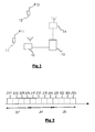
- Figure 1 illustrates a mobile radio communication network, for example a CDMA radio communication system comprising mobile terminals 11, 12, a fixed station 10 and a radio network controller 13.
- a CDMA radio communication system comprising mobile terminals 11, 12, a fixed station 10 and a radio network controller 13.
- Mobile terminal 11 communicates with fixed station 10 by sending a signal over a radio channel with a transmitting power P11, respectively P12.
- Fixed station 10 is connected to radio network controller 13 controlling possibly other fixed stations 14 of the CDMA radio communication network.
- the transmitting powers P11 and P12 are dynamically adapted thanks to an inner-loop power control procedure according to quality measurements processed at fixed station 10 or at radio network controller 13. Commands to adapt the values P11 and P12 are transmitted over a radio signaling channel between fixed station 10 and mobile terminals 11, 12.
- the inner-loop power control ensures that the signal received from mobile terminal 11, respectively mobile terminal 12, fulfills a current signal quality target.
- the current signal quality target at the entry of fixed station 10 is determined in order to guarantee a predefined frame quality target, after decoding of the signal, required by the network.
- the predefined frame quality target is in general service dependant. For voice services telephony it can for example correspond to a frame error rate of 0.01 and for a special class of data services it may correspond to a bit error rate of 10 -5 .
- the determination of the appropriate current signal quality target corresponding to the required frame quality target after decoding is the object of the outer-loop power control and depends essentially on propagation conditions.
- Figure 2 illustrates the structure of the signal transmitted from mobile terminal 11, respectively mobile terminal 12, to fixed station 10.
- the signal is constituted of a succession of frames 20, 21, 22 and each frame 20, 21, 22 is divided in slots 201, ..., 204, 211, ..., 214, 221, ..., 224.
- the slot size, number of slots in a frame as well as the size of a frame are system parameters.
- the elementary entity of a slot or a frame is a bit or a chip.
- this signal Before being transmitted on the air channel, this signal is modulated and preferably spread with a PN sequence.
- the signal is also preferably interleaved before being transmitted on the radio channel with a predefined interleaving period.
- the interleaving period comprises a predefined number of slots but may be different from the frame duration defined as system parameter. However it is assumed for this invention that a frame has to be understood as a predefined number of slots. As a consequence, as well the frame defined as system parameter as the interleaving period have to be considered as frames.
- the signal After reception at the antenna of the fixed station 10, the signal is despread and demodulated.
- Figure 3A describes an embodiment of the method of adjusting the signal quality target to ensure that the predefined frame quality target is guaranteed for the current used service. Steps 31i to 36i are executed for each single frame.
- Step 31i consists in measuring signal quality indicators at slot level in a currently received frame, called frame i. For example, for frame 20, an energy per bit related to a spectral noise density Eb/NO 1 , ..., Eb/N0 4 is measured for each slot 201, ..., 204 of frame 20.
- Steps 32i to 36i illustrate how the signal quality indicators at slot level are used to deduce a frame quality indicator for the currently received frame.
- Step 32i consists in converting each signal quality indicator at slot level in a slot quality indicator before decoding.
- the slot quality indicator before decoding can be a raw bit error rate before decoding.
- the conversion relies on a predefined non-linear relation.
- Step 33i consists in calculating a value related to variations of the signal quality indicators at slot level measured in the currently received frame.
- This value may be the standard deviation value, the variance or any quantity representing the variations of the signal quality indicators measured at slot level in a frame.
- Eb/NO(slot) a value related to the standard deviation of slot quality indicators before decoding rawBER(slot) may also be used.
- Step 34i consists in generating the average value of the slot quality indicators before decoding rawBER(slot) along the frame. This step enables it to get rid of interleaving effects and associates a single frame quality value before decoding to the currently received frame. In this example it is assumed that a frame is as large as the interleaving period.
- the relation between the frame quality indicator before decoding and the frame quality indicator obtained after decoding was found to be a network of curves parameterized by a value related to the standard deviation of signal quality indicators at slot level.
- Each curve of the network of curves is preferably approximated by polynomial curve, which coefficients are parameterized by the value related to the standard deviation of the signal quality indicators measured at slot level in the received frame.
- the curves and the coefficients of the polynomial may be obtained by simulation.
- Step 35i consists in selecting the curve of the network of curves corresponding to the value related to the standard deviation of the signal quality indicators measured at slot level in the frame obtained at step 33i.
- Step 36i consists in calculating the frame quality indicator by applying the frame quality indicator before decoding obtained at step 34i to the polynomial function selected at step 35i.
- the further steps of the method illustrate how the signal quality target is adjusted according to the difference between the deduced frame quality indicator of frame i and the predefined frame quality target.
- Step 37i consists in comparing the average value of the frame quality indicators to the predefined frame quality target. If the average value is smaller than the target value the signal quality target is decreased by a value STEP UP, if it is higher the signal quality target is increased by a value STEP DOWN.
- the values STEP UP AND STEP DOWN are preferably proportional to the gap between the average frame quality indicator and the frame quality target.
- N is preferably a small number which has not the inconvenient to delay too much the adjustment of the signal quality target.
- Step 300 to 302 describe the adjustment procedure.
- Step 300 consists in generating an average value of the frame quality indicators estimated for each one of the N frames according to steps 31i to 36i.
- Step 301 consists in generating the average value of the frame quality indicators for the N considered frames.
- Step 302 consists in determining the adjustment to apply to the signal quality target. If the average frame quality indicator is lower than the frame quality target, the signal quality target is decreased by a value STEP UP, if it is higher the signal quality target is increased by a value STEP DOWN.
- the values STEP UP AND STEP DOWN are preferably proportional to the gap between the average frame quality indicator and the frame quality target.
- FIG 4 is a bloc diagram of an embodiment of a transceiver 40 belonging to a CDMA radio communication network according to the invention.
- Transceiver 40 corresponds preferably to mobile terminal 11 or mobile terminal 12 showed on figure 1.
- Transceiver 40 comprises an antenna 41 to receive a radio signal. Antenna 41 is connected to a signal quality estimator 42 to measure signal quality indicators at slot level for each slot of a frame of the received signal.
- the signal quality estimator42 is connected to a first filter 43 and to a second filter 44.
- the second filter 44 is connected to a curve selection module 45.
- the first filter 43 and the curve selection module 45 are connected to a frame quality estimator 46 which is in turn connected to an adjustment estimator 47 which adjusts the value of a signal quality target.
- Signal quality estimator 42 is designed to measure for each slot of a currently received frame a signal quality indicator.
- This signal quality indicator is preferably an energy pro bit related to a spectral noise density (EB/NO). Alternatively it can also be a signal to interference ratio (SIR).
- EB/NO spectral noise density
- SIR signal to interference ratio
- the measured signal quality indicators at slot level are inputs of the first filter 43, which is designed to convert each signal quality indicator at slot level , Eb/NO(i), in slot quality indicators before decoding by using a predefined non-linear function, named P, physically stored in a memory accessible by the first filter 43 and to average the obtained slot quality indicator before decoding for the frame period thus obtaining a raw frame quality indicator, noted rawBER.
- a predefined non-linear function named P
- the signal quality indicators at slot level measured in the currently received frame are also inputs for the second filter 44, which evaluate the variations of the signal quality indicators at slot level during the frame period.
- the variations are preferably estimated by calculating the standard deviation of the signal quality indicators measured at slot level for the frame period. Alternatively the variance could also be used.
- the calculated variations are used by the curve selection module to select among a set of curves parameterized by the variation the appropriate one.
- the curves of the set of curves are physically stored in a memory accessible by the curve selection module.
- the frame quality estimator 46 converts the raw frame quality indicator calculated by first filter 43 by using the curve selected in the curve selection module 45 to obtain a frame quality indicator for the currently received frame.
- the adjustment estimator 47 determines the adjustment of the signal quality target according to the difference between the frame quality indicator and the predefined frame quality target.
- the fixed station preferably contains only the signal quality estimator 42, the first filter 43 and the second filter 44, the curve selection module 45 as well as the adjustment estimator 46 being located in the radio network controller.
- the fixed station transmits preferably the frame quality indicator before decoding calculated in the first filter 42 and the variation of the signal quality indicators at slot level calculated in the second filter 43 to the radio network controller over a signaling channel.
- the radio network controller comprises means for extracting these two values from the signaling channel and feeds the value representing the variation of signal quality indicators to the curve selection module 45 and the frame quality indicator before decoding to the adjustment estimator 46.
- Any other arrangement of the different modules (first filter 43, second filter 44, curve selection module 45 and adjustment estimator 46) between the fixed station and the radio network controller may be implemented on condition that the information exchange between the fixed station and the radio network controller is properly defined.
Landscapes
- Engineering & Computer Science (AREA)
- Computer Networks & Wireless Communication (AREA)
- Signal Processing (AREA)
- Mobile Radio Communication Systems (AREA)
- Transmitters (AREA)
Abstract
Description
rawBER(slot)=P(Eb/N0(slot)).

Claims (10)
- A method of adjusting a signal quality target at a transceiver (10, 11, 12) of a code division multiple access (CDMA) radio communication network, said transceiver (10, 11, 12) receiving a signal carrying a frame structure (20, 21, 22), each frame (20, 21, 22) being divided in slots (201, ..., 204, 211, ..., 214, 221, ..., 224), said signal quality target ensuring a predefined frame quality target to be reached in power control procedures, said method being characterized by comprising the steps of:computing for a received frame (20, 21, 22), a frame quality indicator depending on signal quality indicators measured at slot level in said received frame (20, 21, 22); andadjusting said signal quality target according to the difference between said frame quality indicator and said predefined frame quality target.
- A method according to claim 1, characterized in that said frame quality indicator depends on variations of said signal quality indicators measured at slot level in said received frame (20, 21, 22), said variations being represented by a value related to the standard deviation of said signal quality indicators measured at slot level in said received frame (20, 21, 22).
- A method according to one of the claims 1 or 2, characterized in that said frame quality indicator further depends on the average value of slot quality indicators before decoding, each slot quality indicator before decoding being derived from one of said signal quality indicators measured at slot level in said frame (20, 21, 22) thanks to a predefined non linear relation.
- A method according to one of the claims 1 to 3, characterized in that the relation between said frame quality indicator and said average value of said slot quality before decoding is a polynomial, which coefficients are parameterized by said value related to the standard deviation of said signal quality indicators measured at slot level in said received frame (20, 21, 22).
- A method according to one of the claims 1 to 4, characterized in that said frame is chosen as large as an interleaving period.
- A transceiver (40) part of a code division multiple access (CDMA) radio communication network, said transceiver receiving a signal carrying a frame structure, each frame (20, 21, 22) being divided in slots (201, ..., 204, 211, ..., 214, 221, ..., 224), characterized in that said transceiver (40) comprises:a signal quality estimator (42) to measure signal quality indicators at slot level in a frame (20,21,22);a first filter (43) to calculate an average value of slot quality indicators before decoding derived from said signal quality indicators measured at slot level by using a predefined non-linear relationa second filter (44) to calculate a value related to variations of said signal quality indicators measured at slot level in said frame.
- A transceiver (40) according to claim 6, characterized in that said transceiver further comprises:a curve selection module (45) to select one relation out of a set of predefined relations parameterized by said value related to variations of said signal quality indicators measured at slot level in said frame (20, 21, 22);a frame quality estimator (46) to evaluate a frame quality indicator for said frame (20, 21, 22); andan adjustment estimator (47) to adjust a signal quality target according to the difference between said frame quality indicator and a predefined frame quality target.
- A transceiver (40) according any of the claims 6 and 7, characterized in that said transceiver (40) is a mobile station (11, 12) of a CDMA radio communication network.
- A transceiver (40) according to claim 6, characterized in that said transceiver (40) is a fixed station (10) of a CDMA radio communication network.
- A radio network controller (13) part of a code division multiple access (CDMA) radio communication network, said radio network controller adjusting a signal quality target to ensure a predefined target frame quality, characterized in that said radio network (13) controller comprises:an input receiver to receive a parameter corresponding to a variation of a signal quality indicator in a frame (20, 21, 22);a curve selection module (45) to select one relation out of a set of predefined relations parameterized by said value related to variations of said signal quality indicators measured at slot level in said frame (20, 21, 22);a frame quality estimator (46) to evaluate a frame quality indicator for said frame (20, 21, 22); andan adjustment estimator (47) to adjust said signal quality target according to the difference between said frame quality indicator and said predefined frame quality target.
Priority Applications (5)
| Application Number | Priority Date | Filing Date | Title |
|---|---|---|---|
| DE60036273T DE60036273T2 (en) | 2000-02-21 | 2000-02-21 | A method for setting a signal quality setpoint during transmission power control in a CDMA radio communication network |
| AT00440052T ATE372610T1 (en) | 2000-02-21 | 2000-02-21 | METHOD FOR SETTING A SIGNAL QUALITY SET POINT DURING TRANSMIT POWER CONTROL IN A CDMA RADIO COMMUNICATIONS NETWORK |
| EP00440052A EP1128572B1 (en) | 2000-02-21 | 2000-02-21 | A method of adjusting a signal quality target during transmission power control in a CDMA radio communication network |
| US09/572,461 US6963553B1 (en) | 2000-02-21 | 2000-05-17 | Method of adjusting a signal quality target to be reached in power control procedures in a CDMA radio communication network and a corresponding transceiver |
| CNB011046759A CN1226840C (en) | 2000-02-21 | 2001-02-21 | Method for regulating to reach signal quality target and relevant transceiver |
Applications Claiming Priority (1)
| Application Number | Priority Date | Filing Date | Title |
|---|---|---|---|
| EP00440052A EP1128572B1 (en) | 2000-02-21 | 2000-02-21 | A method of adjusting a signal quality target during transmission power control in a CDMA radio communication network |
Publications (2)
| Publication Number | Publication Date |
|---|---|
| EP1128572A1 true EP1128572A1 (en) | 2001-08-29 |
| EP1128572B1 EP1128572B1 (en) | 2007-09-05 |
Family
ID=8174101
Family Applications (1)
| Application Number | Title | Priority Date | Filing Date |
|---|---|---|---|
| EP00440052A Expired - Lifetime EP1128572B1 (en) | 2000-02-21 | 2000-02-21 | A method of adjusting a signal quality target during transmission power control in a CDMA radio communication network |
Country Status (5)
| Country | Link |
|---|---|
| US (1) | US6963553B1 (en) |
| EP (1) | EP1128572B1 (en) |
| CN (1) | CN1226840C (en) |
| AT (1) | ATE372610T1 (en) |
| DE (1) | DE60036273T2 (en) |
Cited By (4)
| Publication number | Priority date | Publication date | Assignee | Title |
|---|---|---|---|---|
| GB2389746A (en) * | 2002-05-03 | 2003-12-17 | Lg Electronics Inc | A switch frame or handover frame containing a first slot having channel quality information and a second slot having cell/sector switching information |
| EP1788720A3 (en) * | 2002-06-24 | 2007-06-13 | QUALCOMM Incorporated | Apparatus and method for outer loop uplink power control during link imbalance |
| WO2012050506A1 (en) * | 2010-10-12 | 2012-04-19 | Telefonaktiebolaget L M Ericsson (Publ) | Uplink power control |
| EP2520056A4 (en) * | 2009-12-30 | 2014-09-17 | Ericsson Telefon Ab L M | Method of and node b and user equipment for power control in case of segmentation |
Families Citing this family (11)
| Publication number | Priority date | Publication date | Assignee | Title |
|---|---|---|---|---|
| FI108772B (en) * | 1998-03-31 | 2002-03-15 | Nokia Corp | Procedure for controlling the connections to a mobile station |
| JP3839406B2 (en) * | 2001-01-17 | 2006-11-01 | 富士通株式会社 | Outer loop power control apparatus and method |
| IN2012DN00923A (en) | 2003-05-15 | 2015-04-03 | Huawei Tech Co Ltd | |
| US20050064821A1 (en) * | 2003-09-22 | 2005-03-24 | Telefonaktiebolaget Lm Ericsson (Publ) | Alternative service management |
| US7283792B2 (en) * | 2004-10-15 | 2007-10-16 | Nokia Corporation | Method and apparatus for providing limiting power adjustment in a wireless communication system |
| US9130706B2 (en) * | 2005-05-26 | 2015-09-08 | Unwired Planet, Llc | Method and apparatus for signal quality loss compensation in multiplexing transmission systems |
| GB0705325D0 (en) * | 2007-03-20 | 2007-04-25 | Skype Ltd | Method of transmitting data in a communication system |
| US8265681B2 (en) * | 2007-09-12 | 2012-09-11 | Telefonaktiebolaget Lm Ericsson (Publ) | Outer loop transmit power control in wireless communication systems |
| JP5145852B2 (en) * | 2007-10-15 | 2013-02-20 | 日本電気株式会社 | Coefficient determination device, radio communication system, coefficient determination method, and coefficient determination program |
| CN101911550B (en) * | 2008-03-27 | 2014-01-08 | 松下北美公司美国分部松下汽车系统公司 | Method and apparatus for dynamically adapting FM tuner sensitivity to a local environment for a single-tuner system |
| US8406715B2 (en) * | 2008-03-27 | 2013-03-26 | Panasonic Automotive Systems of America, division of Panasonic Corporation of North America | Method and apparatus for dynamically adapting FM tuner sensitivity to a local environment for a single-tuner system |
Citations (2)
| Publication number | Priority date | Publication date | Assignee | Title |
|---|---|---|---|---|
| EP0949768A2 (en) * | 1998-04-08 | 1999-10-13 | Nokia Mobile Phones Ltd. | Method and system for controlling the transmission power during macrodiversity |
| EP0963059A2 (en) * | 1998-06-04 | 1999-12-08 | Nec Corporation | A CDMA mobile communication system and a transmission power control method for the same |
Family Cites Families (17)
| Publication number | Priority date | Publication date | Assignee | Title |
|---|---|---|---|---|
| US5822318A (en) * | 1994-07-29 | 1998-10-13 | Qualcomm Incorporated | Method and apparatus for controlling power in a variable rate communication system |
| US5629934A (en) * | 1995-06-30 | 1997-05-13 | Motorola, Inc. | Power control for CDMA communication systems |
| US5790596A (en) * | 1996-03-15 | 1998-08-04 | Motorola, Inc. | Radiotelephone communication unit displaying chronological information |
| US5893035A (en) * | 1996-09-16 | 1999-04-06 | Qualcomm Incorporated | Centralized forward link power control |
| US6084904A (en) * | 1997-07-25 | 2000-07-04 | Motorola, Inc. | Method and apparatus for adjusting a power control setpoint threshold in a wireless communication system |
| FI104527B (en) * | 1997-09-17 | 2000-02-15 | Nokia Mobile Phones Ltd | Customizable radio link |
| US6128506A (en) * | 1997-09-24 | 2000-10-03 | Telefonaktiebolaget Lm Ericsson | Integrated power control and congestion control in a communication system |
| US6181738B1 (en) * | 1998-02-13 | 2001-01-30 | Northern Telecom Limited | Reverse link power control using a frame quality metric |
| JP3125776B2 (en) * | 1998-03-27 | 2001-01-22 | 日本電気株式会社 | Transmission power control method and base station apparatus in cellular system |
| EP0975118B1 (en) * | 1998-07-24 | 2007-05-09 | Matsushita Electric Industrial Co., Ltd. | CDMA radio communication system and method |
| US6535723B1 (en) * | 1999-03-15 | 2003-03-18 | Lucent Technologies Inc. | Method of power control for a wireless communication system having multiple information rates |
| US6226283B1 (en) * | 1999-05-13 | 2001-05-01 | Motorola, Inc. | Method and selector for performing selection in a communication system |
| ES2216459T3 (en) * | 1999-05-21 | 2004-10-16 | Alcatel | METHOD FOR IMPROVING THE PERFORMANCE OF A MOBILE RADIOCOMMUNICATION SYSTEM USING THE CONVERGENCE ASSESSMENT OF THE POWER CONTROL LOOP. |
| US6493541B1 (en) * | 1999-07-02 | 2002-12-10 | Telefonaktiebolaget Lm Ericsson (Publ) | Transmit power control time delay compensation in a wireless communications system |
| US6285886B1 (en) * | 1999-07-08 | 2001-09-04 | Lucent Technologies Inc. | Method for controlling power for a communications system having multiple traffic channels per subscriber |
| EP1578028B1 (en) * | 1999-07-13 | 2009-03-25 | Alcatel Lucent | A method for improving performances of a mobile radiocommunication system using a power control algorithm |
| US6298242B1 (en) * | 1999-07-22 | 2001-10-02 | Qualcomm Inc. | Method and apparatus for reducing frame error rate through signal power adjustment |
-
2000
- 2000-02-21 AT AT00440052T patent/ATE372610T1/en not_active IP Right Cessation
- 2000-02-21 DE DE60036273T patent/DE60036273T2/en not_active Expired - Lifetime
- 2000-02-21 EP EP00440052A patent/EP1128572B1/en not_active Expired - Lifetime
- 2000-05-17 US US09/572,461 patent/US6963553B1/en not_active Expired - Lifetime
-
2001
- 2001-02-21 CN CNB011046759A patent/CN1226840C/en not_active Expired - Fee Related
Patent Citations (2)
| Publication number | Priority date | Publication date | Assignee | Title |
|---|---|---|---|---|
| EP0949768A2 (en) * | 1998-04-08 | 1999-10-13 | Nokia Mobile Phones Ltd. | Method and system for controlling the transmission power during macrodiversity |
| EP0963059A2 (en) * | 1998-06-04 | 1999-12-08 | Nec Corporation | A CDMA mobile communication system and a transmission power control method for the same |
Cited By (11)
| Publication number | Priority date | Publication date | Assignee | Title |
|---|---|---|---|---|
| GB2389746A (en) * | 2002-05-03 | 2003-12-17 | Lg Electronics Inc | A switch frame or handover frame containing a first slot having channel quality information and a second slot having cell/sector switching information |
| GB2389746B (en) * | 2002-05-03 | 2006-01-04 | Lg Electronics Inc | Switch frame, method of transmitting the switch frame and a quality indicator channel structure including the switch frame |
| CN100431313C (en) * | 2002-05-03 | 2008-11-05 | Lg电子株式会社 | Method for transmitting switching frame |
| US7499430B2 (en) | 2002-05-03 | 2009-03-03 | Lg Electronics Inc. | Switch frame, method of transmitting the switch frame and a quality indicator channel structure including the switch frame |
| KR100932482B1 (en) | 2002-05-03 | 2009-12-17 | 엘지전자 주식회사 | Frame transmission method for cell or sector switching |
| EP1788720A3 (en) * | 2002-06-24 | 2007-06-13 | QUALCOMM Incorporated | Apparatus and method for outer loop uplink power control during link imbalance |
| US8160027B2 (en) | 2002-06-24 | 2012-04-17 | Qualcomm Incorporated | Uplink power control |
| EP2520056A4 (en) * | 2009-12-30 | 2014-09-17 | Ericsson Telefon Ab L M | Method of and node b and user equipment for power control in case of segmentation |
| US8982791B2 (en) | 2009-12-30 | 2015-03-17 | Telefonaktiebolaget L M Ericsson (Publ) | Method of and Node B and user equipment for power control in case of segmentation |
| WO2012050506A1 (en) * | 2010-10-12 | 2012-04-19 | Telefonaktiebolaget L M Ericsson (Publ) | Uplink power control |
| US8855700B2 (en) | 2010-10-12 | 2014-10-07 | Telefonaktiebolaget L M Ericsson (Publ) | Uplink power control |
Also Published As
| Publication number | Publication date |
|---|---|
| CN1310530A (en) | 2001-08-29 |
| US6963553B1 (en) | 2005-11-08 |
| EP1128572B1 (en) | 2007-09-05 |
| DE60036273D1 (en) | 2007-10-18 |
| DE60036273T2 (en) | 2007-12-27 |
| CN1226840C (en) | 2005-11-09 |
| ATE372610T1 (en) | 2007-09-15 |
Similar Documents
| Publication | Publication Date | Title |
|---|---|---|
| US7386321B2 (en) | Base station apparatus and radio communication method | |
| EP0683570B1 (en) | Transmission power control for mobile radio communications using a CDMA and Viterbi decoding | |
| US5873028A (en) | Transmission power control apparatus and method in a mobile communication system | |
| KR100401217B1 (en) | Outer loop/weighted open loop power control in a time division duplex communication system | |
| KR100331402B1 (en) | Method and apparatus for adjusting a power control setpoint threshold in a wireless communication system | |
| US7697953B2 (en) | Outer loop transmit power control using channel-adaptive processing | |
| US6108374A (en) | System and method for measuring channel quality information | |
| EP1128572B1 (en) | A method of adjusting a signal quality target during transmission power control in a CDMA radio communication network | |
| US7738902B2 (en) | Transmission power control method | |
| KR100366799B1 (en) | Transmission power control method of mobile communication system | |
| WO1997050197A1 (en) | Transmitted power controller | |
| AU7304598A (en) | Method and apparatus for adjusting thresholds and measurements of rec eived signals by anticipating power control commands yet to be executed | |
| CN103997776A (en) | Erasure detection and power control for a transport channel with unknown format in a wireless communication system | |
| KR20010050378A (en) | POWER CONTROL WITH EFFECTIVE Eb/No | |
| US20080108315A1 (en) | Method and arrangement for controlling transmission power and a network element | |
| US7817972B2 (en) | Method and arrangement for mutual information based power control | |
| CN101171776B (en) | Transmission power control method and apparatus | |
| US20030156554A1 (en) | Method for regulating transmission power in a radiocommunications system | |
| JP3860538B2 (en) | Method for adjusting transmission power in wireless system | |
| WO2005070187A2 (en) | Downlink power control in wireless communications networks and methods | |
| WO2004034614A1 (en) | A method and device for estimating a signal to interference ratio (sir) in wcdma systems | |
| US8010148B2 (en) | Mobile terminal and control method therefor | |
| CN100361415C (en) | Method for adjusting transmission power in mobile wireless communication system and corresponding mobile wireless communication system | |
| US7076264B2 (en) | Power control in a cellular system using ES/IO and NT/I0 values | |
| EP2333987B1 (en) | Radio channel control method and receiving apparatus |
Legal Events
| Date | Code | Title | Description |
|---|---|---|---|
| PUAI | Public reference made under article 153(3) epc to a published international application that has entered the european phase |
Free format text: ORIGINAL CODE: 0009012 |
|
| 17P | Request for examination filed |
Effective date: 20001123 |
|
| AK | Designated contracting states |
Kind code of ref document: A1 Designated state(s): AT BE CH CY DE DK ES FI FR GB GR IE IT LI LU MC NL PT SE |
|
| AX | Request for extension of the european patent |
Free format text: AL;LT;LV;MK;RO;SI |
|
| AKX | Designation fees paid |
Free format text: AT BE CH CY DE DK ES FI FR GB GR IE IT LI LU MC NL PT SE |
|
| 17Q | First examination report despatched |
Effective date: 20061009 |
|
| GRAP | Despatch of communication of intention to grant a patent |
Free format text: ORIGINAL CODE: EPIDOSNIGR1 |
|
| RAP1 | Party data changed (applicant data changed or rights of an application transferred) |
Owner name: ALCATEL LUCENT |
|
| GRAS | Grant fee paid |
Free format text: ORIGINAL CODE: EPIDOSNIGR3 |
|
| GRAA | (expected) grant |
Free format text: ORIGINAL CODE: 0009210 |
|
| AK | Designated contracting states |
Kind code of ref document: B1 Designated state(s): AT BE CH CY DE DK ES FI FR GB GR IE IT LI LU MC NL PT SE |
|
| REG | Reference to a national code |
Ref country code: GB Ref legal event code: FG4D |
|
| REG | Reference to a national code |
Ref country code: CH Ref legal event code: EP |
|
| REF | Corresponds to: |
Ref document number: 60036273 Country of ref document: DE Date of ref document: 20071018 Kind code of ref document: P |
|
| REG | Reference to a national code |
Ref country code: IE Ref legal event code: FG4D |
|
| ET | Fr: translation filed | ||
| PG25 | Lapsed in a contracting state [announced via postgrant information from national office to epo] |
Ref country code: ES Free format text: LAPSE BECAUSE OF FAILURE TO SUBMIT A TRANSLATION OF THE DESCRIPTION OR TO PAY THE FEE WITHIN THE PRESCRIBED TIME-LIMIT Effective date: 20071216 Ref country code: FI Free format text: LAPSE BECAUSE OF FAILURE TO SUBMIT A TRANSLATION OF THE DESCRIPTION OR TO PAY THE FEE WITHIN THE PRESCRIBED TIME-LIMIT Effective date: 20070905 |
|
| PG25 | Lapsed in a contracting state [announced via postgrant information from national office to epo] |
Ref country code: CH Free format text: LAPSE BECAUSE OF FAILURE TO SUBMIT A TRANSLATION OF THE DESCRIPTION OR TO PAY THE FEE WITHIN THE PRESCRIBED TIME-LIMIT Effective date: 20070905 Ref country code: LI Free format text: LAPSE BECAUSE OF FAILURE TO SUBMIT A TRANSLATION OF THE DESCRIPTION OR TO PAY THE FEE WITHIN THE PRESCRIBED TIME-LIMIT Effective date: 20070905 Ref country code: AT Free format text: LAPSE BECAUSE OF FAILURE TO SUBMIT A TRANSLATION OF THE DESCRIPTION OR TO PAY THE FEE WITHIN THE PRESCRIBED TIME-LIMIT Effective date: 20070905 |
|
| NLV1 | Nl: lapsed or annulled due to failure to fulfill the requirements of art. 29p and 29m of the patents act | ||
| PG25 | Lapsed in a contracting state [announced via postgrant information from national office to epo] |
Ref country code: BE Free format text: LAPSE BECAUSE OF FAILURE TO SUBMIT A TRANSLATION OF THE DESCRIPTION OR TO PAY THE FEE WITHIN THE PRESCRIBED TIME-LIMIT Effective date: 20070905 |
|
| REG | Reference to a national code |
Ref country code: CH Ref legal event code: PL |
|
| PG25 | Lapsed in a contracting state [announced via postgrant information from national office to epo] |
Ref country code: GR Free format text: LAPSE BECAUSE OF FAILURE TO SUBMIT A TRANSLATION OF THE DESCRIPTION OR TO PAY THE FEE WITHIN THE PRESCRIBED TIME-LIMIT Effective date: 20071206 Ref country code: NL Free format text: LAPSE BECAUSE OF FAILURE TO SUBMIT A TRANSLATION OF THE DESCRIPTION OR TO PAY THE FEE WITHIN THE PRESCRIBED TIME-LIMIT Effective date: 20070905 |
|
| PG25 | Lapsed in a contracting state [announced via postgrant information from national office to epo] |
Ref country code: PT Free format text: LAPSE BECAUSE OF FAILURE TO SUBMIT A TRANSLATION OF THE DESCRIPTION OR TO PAY THE FEE WITHIN THE PRESCRIBED TIME-LIMIT Effective date: 20080206 |
|
| PG25 | Lapsed in a contracting state [announced via postgrant information from national office to epo] |
Ref country code: SE Free format text: LAPSE BECAUSE OF FAILURE TO SUBMIT A TRANSLATION OF THE DESCRIPTION OR TO PAY THE FEE WITHIN THE PRESCRIBED TIME-LIMIT Effective date: 20071205 |
|
| PLBE | No opposition filed within time limit |
Free format text: ORIGINAL CODE: 0009261 |
|
| STAA | Information on the status of an ep patent application or granted ep patent |
Free format text: STATUS: NO OPPOSITION FILED WITHIN TIME LIMIT |
|
| PG25 | Lapsed in a contracting state [announced via postgrant information from national office to epo] |
Ref country code: DK Free format text: LAPSE BECAUSE OF FAILURE TO SUBMIT A TRANSLATION OF THE DESCRIPTION OR TO PAY THE FEE WITHIN THE PRESCRIBED TIME-LIMIT Effective date: 20070905 |
|
| 26N | No opposition filed |
Effective date: 20080606 |
|
| PG25 | Lapsed in a contracting state [announced via postgrant information from national office to epo] |
Ref country code: MC Free format text: LAPSE BECAUSE OF NON-PAYMENT OF DUE FEES Effective date: 20080228 |
|
| PG25 | Lapsed in a contracting state [announced via postgrant information from national office to epo] |
Ref country code: IE Free format text: LAPSE BECAUSE OF NON-PAYMENT OF DUE FEES Effective date: 20080221 |
|
| PG25 | Lapsed in a contracting state [announced via postgrant information from national office to epo] |
Ref country code: CY Free format text: LAPSE BECAUSE OF FAILURE TO SUBMIT A TRANSLATION OF THE DESCRIPTION OR TO PAY THE FEE WITHIN THE PRESCRIBED TIME-LIMIT Effective date: 20070905 |
|
| PG25 | Lapsed in a contracting state [announced via postgrant information from national office to epo] |
Ref country code: LU Free format text: LAPSE BECAUSE OF NON-PAYMENT OF DUE FEES Effective date: 20080221 |
|
| PG25 | Lapsed in a contracting state [announced via postgrant information from national office to epo] |
Ref country code: IT Free format text: LAPSE BECAUSE OF NON-PAYMENT OF DUE FEES Effective date: 20080229 |
|
| REG | Reference to a national code |
Ref country code: FR Ref legal event code: GC Effective date: 20131018 |
|
| REG | Reference to a national code |
Ref country code: FR Ref legal event code: RG Effective date: 20141016 |
|
| REG | Reference to a national code |
Ref country code: FR Ref legal event code: PLFP Year of fee payment: 16 |
|
| REG | Reference to a national code |
Ref country code: FR Ref legal event code: CA Effective date: 20150521 |
|
| REG | Reference to a national code |
Ref country code: FR Ref legal event code: CA Effective date: 20150521 |
|
| REG | Reference to a national code |
Ref country code: FR Ref legal event code: PLFP Year of fee payment: 17 |
|
| PGFP | Annual fee paid to national office [announced via postgrant information from national office to epo] |
Ref country code: DE Payment date: 20160218 Year of fee payment: 17 |
|
| PGFP | Annual fee paid to national office [announced via postgrant information from national office to epo] |
Ref country code: GB Payment date: 20160217 Year of fee payment: 17 Ref country code: FR Payment date: 20160218 Year of fee payment: 17 |
|
| REG | Reference to a national code |
Ref country code: DE Ref legal event code: R119 Ref document number: 60036273 Country of ref document: DE |
|
| GBPC | Gb: european patent ceased through non-payment of renewal fee |
Effective date: 20170221 |
|
| REG | Reference to a national code |
Ref country code: FR Ref legal event code: ST Effective date: 20171031 |
|
| PG25 | Lapsed in a contracting state [announced via postgrant information from national office to epo] |
Ref country code: DE Free format text: LAPSE BECAUSE OF NON-PAYMENT OF DUE FEES Effective date: 20170901 Ref country code: FR Free format text: LAPSE BECAUSE OF NON-PAYMENT OF DUE FEES Effective date: 20170228 |
|
| PG25 | Lapsed in a contracting state [announced via postgrant information from national office to epo] |
Ref country code: GB Free format text: LAPSE BECAUSE OF NON-PAYMENT OF DUE FEES Effective date: 20170221 |